radio MINI Paceman 2014 (Mini Connected) User Guide
[x] Cancel search | Manufacturer: MINI, Model Year: 2014, Model line: Paceman, Model: MINI Paceman 2014Pages: 282, PDF Size: 6.76 MB
Page 58 of 282
DrivingVehicle equipmentThis chapter describes all series equipment as
well as country-specific and special equipment
offered for this model series.Therefore, it also
describes equipment that may not be found in
your vehicle, for instance due to the selected
special equipment or the country version. This
also applies to safety-related functions and sys‐
tems.
Ignition lock Insert the remote control into the
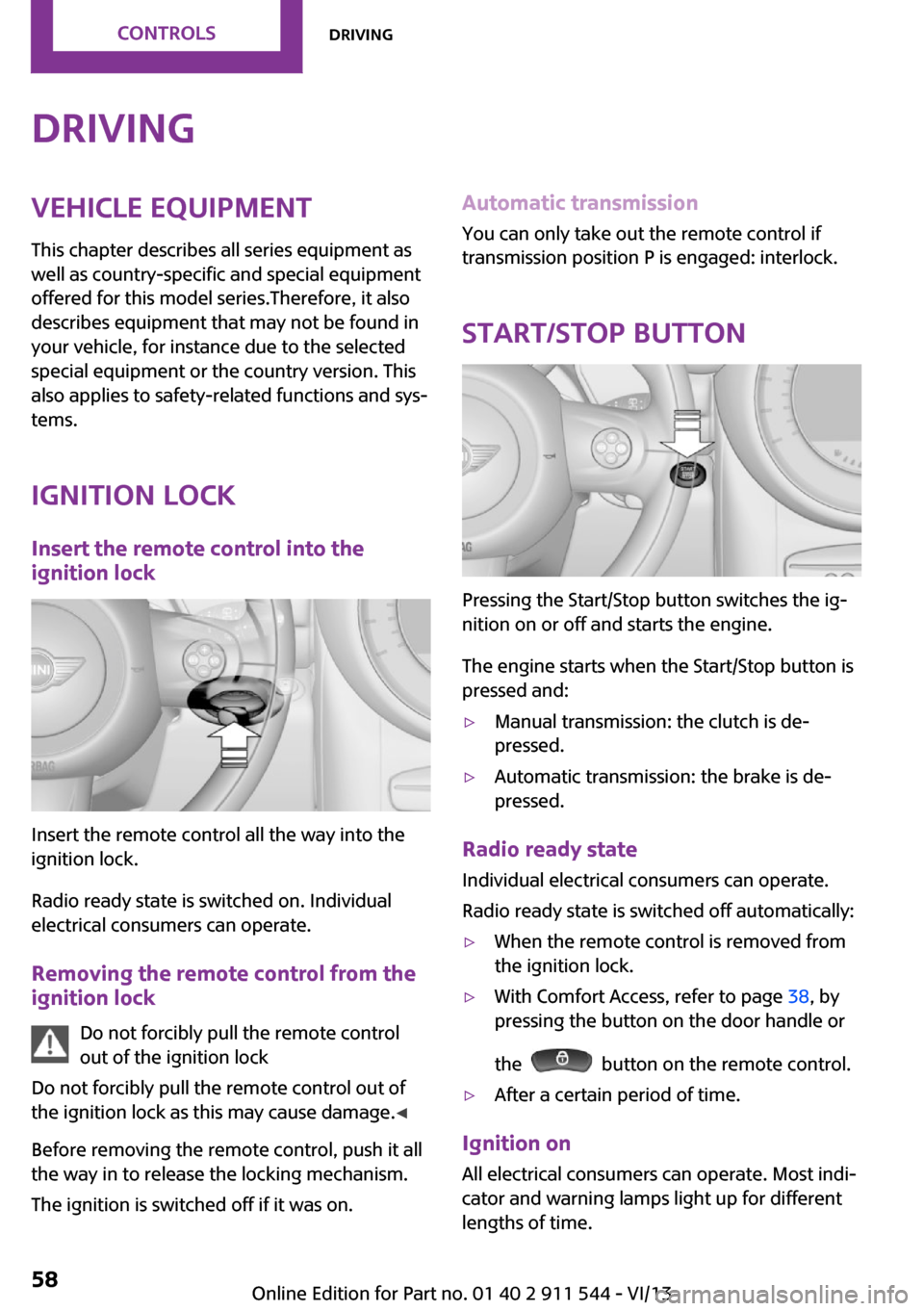
ignition lock
Insert the remote control all the way into the
ignition lock.
Radio ready state is switched on. Individual
electrical consumers can operate.
Removing the remote control from the
ignition lock
Do not forcibly pull the remote control
out of the ignition lock
Do not forcibly pull the remote control out of
the ignition lock as this may cause damage. ◀
Before removing the remote control, push it all
the way in to release the locking mechanism.
The ignition is switched off if it was on.
Automatic transmission
You can only take out the remote control if
transmission position P is engaged: interlock.
Start/Stop button
Pressing the Start/Stop button switches the ig‐
nition on or off and starts the engine.
The engine starts when the Start/Stop button is
pressed and:
▷Manual transmission: the clutch is de‐
pressed.▷Automatic transmission: the brake is de‐
pressed.
Radio ready state
Individual electrical consumers can operate.
Radio ready state is switched off automatically:
▷When the remote control is removed from
the ignition lock.▷With Comfort Access, refer to page 38, by
pressing the button on the door handle or
the
button on the remote control.
▷After a certain period of time.
Ignition on All electrical consumers can operate. Most indi‐
cator and warning lamps light up for different
lengths of time.
Seite 58ControlsDriving58
Online Edition for Part no. 01 40 2 911 544 - VI/13
Page 59 of 282
To save battery power when the engine is off,
switch off the ignition and any unnecessary
electronic systems/power consumers.
Radio ready state and ignition off All indicator and warning lamps in the displays
go out.
The ignition switches off automatically when
the driver's door is opened. Pressing the Start/
Stop button again switches the ignition back
on.
For example, the ignition is not switched off in
the following situations:▷Depress the clutch or brake pedal.▷The low beams are switched on
Starting the engine
General information Enclosed areas
Do not let the engine run in enclosed
areas; otherwise, breathing of exhaust fumes
may lead to loss of consciousness and death.
The exhaust gases contain carbon monoxide,
an odorless and colorless but highly toxic gas. ◀
Unattended vehicle
Do not leave the car unattended with the
engine running; otherwise, it presents a poten‐
tial source of danger.
Before leaving the car with the engine running,
shift to neutral or engage transmission posi‐
tion P and set the handbrake firmly; otherwise,
the vehicle may begin to roll. ◀
Frequent starting in quick succession
Avoid repeated futile attempts at starting
the car and avoid starting the car frequently in
quick succession. Otherwise, the fuel is not
burned or is inadequately burned, and there is
the danger of overheating and damaging the
catalytic converter. ◀
Do not wait for the engine to warm-up while
the vehicle remains stationary; start driving
right away, but at moderate engine speeds.
Do not depress the accelerator when starting
the engine.
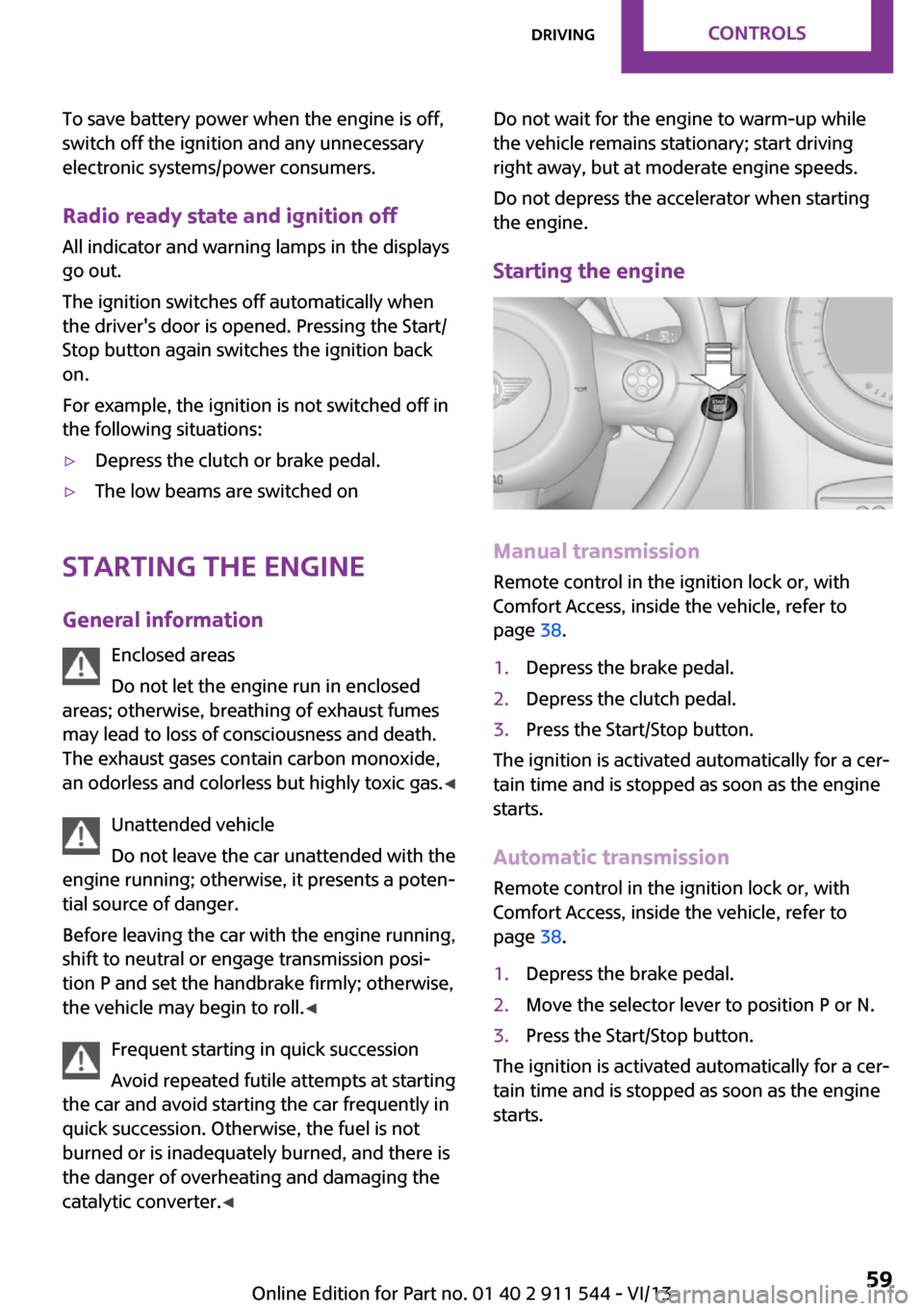
Starting the engine
Manual transmission
Remote control in the ignition lock or, with
Comfort Access, inside the vehicle, refer to
page 38.
1.Depress the brake pedal.2.Depress the clutch pedal.3.Press the Start/Stop button.
The ignition is activated automatically for a cer‐
tain time and is stopped as soon as the engine
starts.
Automatic transmission
Remote control in the ignition lock or, with
Comfort Access, inside the vehicle, refer to
page 38.
1.Depress the brake pedal.2.Move the selector lever to position P or N.3.Press the Start/Stop button.
The ignition is activated automatically for a cer‐
tain time and is stopped as soon as the engine
starts.
Seite 59DrivingControls59
Online Edition for Part no. 01 40 2 911 544 - VI/13
Page 85 of 282
Operational readiness of airbag system
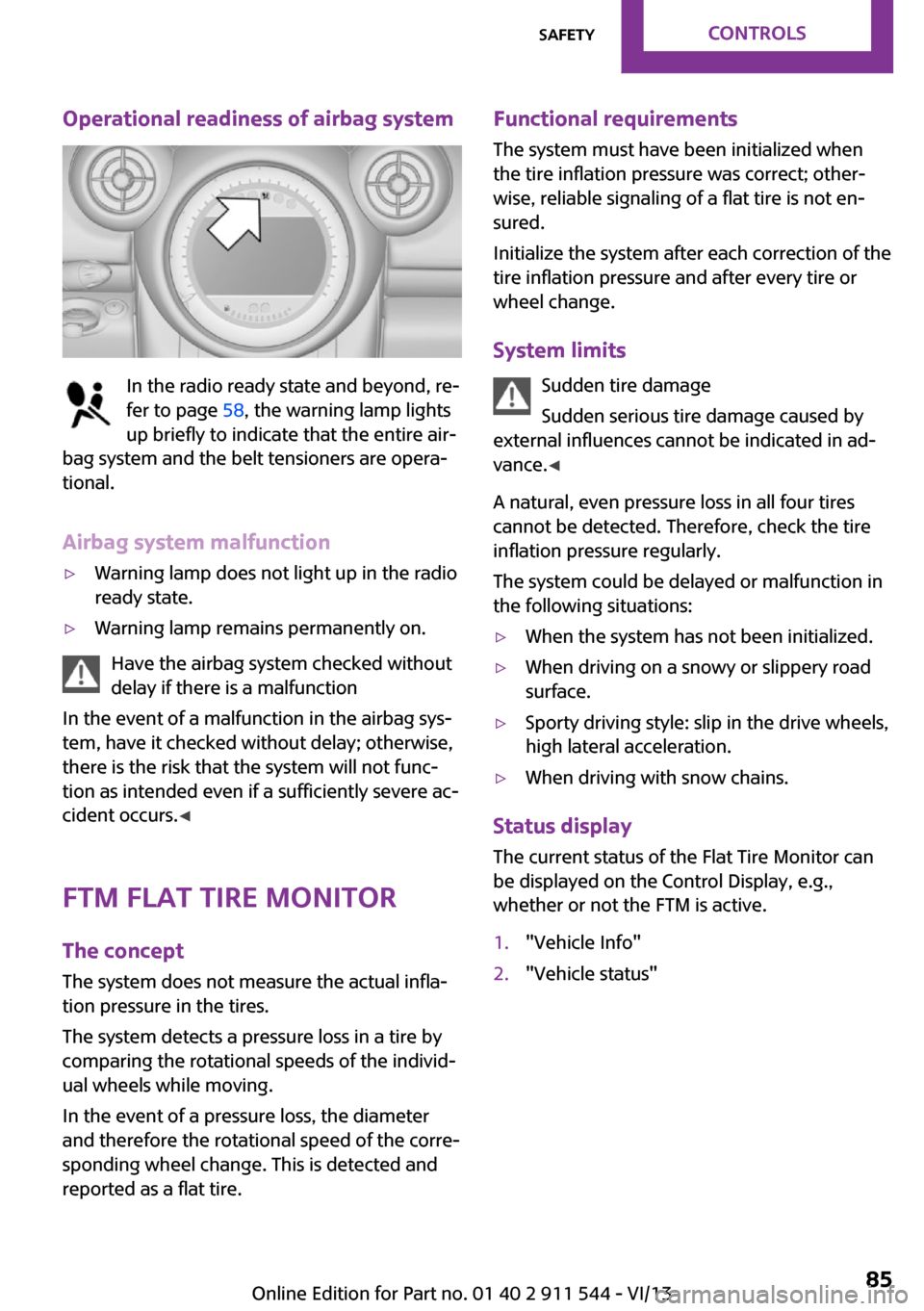
In the radio ready state and beyond, re‐
fer to page 58, the warning lamp lights
up briefly to indicate that the entire air‐
bag system and the belt tensioners are opera‐
tional.
Airbag system malfunction
▷Warning lamp does not light up in the radio
ready state.▷Warning lamp remains permanently on.
Have the airbag system checked without
delay if there is a malfunction
In the event of a malfunction in the airbag sys‐
tem, have it checked without delay; otherwise,
there is the risk that the system will not func‐
tion as intended even if a sufficiently severe ac‐
cident occurs. ◀
FTM Flat Tire Monitor The concept
The system does not measure the actual infla‐
tion pressure in the tires.
The system detects a pressure loss in a tire by
comparing the rotational speeds of the individ‐
ual wheels while moving.
In the event of a pressure loss, the diameter
and therefore the rotational speed of the corre‐
sponding wheel change. This is detected and
reported as a flat tire.
Functional requirements
The system must have been initialized when
the tire inflation pressure was correct; other‐
wise, reliable signaling of a flat tire is not en‐
sured.
Initialize the system after each correction of the
tire inflation pressure and after every tire or
wheel change.
System limits Sudden tire damage
Sudden serious tire damage caused by
external influences cannot be indicated in ad‐
vance. ◀
A natural, even pressure loss in all four tires
cannot be detected. Therefore, check the tire
inflation pressure regularly.
The system could be delayed or malfunction in
the following situations:▷When the system has not been initialized.▷When driving on a snowy or slippery road
surface.▷Sporty driving style: slip in the drive wheels,
high lateral acceleration.▷When driving with snow chains.
Status display
The current status of the Flat Tire Monitor can
be displayed on the Control Display, e.g.,
whether or not the FTM is active.
1."Vehicle Info"2."Vehicle status"Seite 85SafetyControls85
Online Edition for Part no. 01 40 2 911 544 - VI/13
Page 88 of 282
The system is inactive and cannot indicate a flat
tire:▷For a mounted wheel without TPM elec‐
tronics.▷When the TPM is disturbed by other sys‐
tems or devices with the same radio fre‐
quency.
Status display
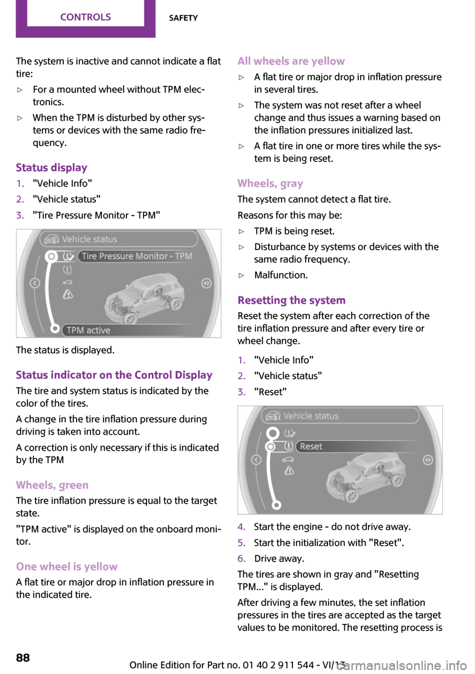
1."Vehicle Info"2."Vehicle status"3."Tire Pressure Monitor - TPM"
The status is displayed.
Status indicator on the Control Display The tire and system status is indicated by the
color of the tires.
A change in the tire inflation pressure during
driving is taken into account.
A correction is only necessary if this is indicated
by the TPM
Wheels, green
The tire inflation pressure is equal to the target
state.
"TPM active" is displayed on the onboard moni‐
tor.
One wheel is yellow A flat tire or major drop in inflation pressure in
the indicated tire.
All wheels are yellow▷A flat tire or major drop in inflation pressure
in several tires.▷The system was not reset after a wheel
change and thus issues a warning based on
the inflation pressures initialized last.▷A flat tire in one or more tires while the sys‐
tem is being reset.
Wheels, gray
The system cannot detect a flat tire.
Reasons for this may be:
▷TPM is being reset.▷Disturbance by systems or devices with the
same radio frequency.▷Malfunction.
Resetting the system
Reset the system after each correction of the
tire inflation pressure and after every tire or
wheel change.
1."Vehicle Info"2."Vehicle status"3."Reset"4.Start the engine - do not drive away.5.Start the initialization with "Reset".6.Drive away.
The tires are shown in gray and "Resetting
TPM..." is displayed.
After driving a few minutes, the set inflation
pressures in the tires are accepted as the target
values to be monitored. The resetting process is
Seite 88ControlsSafety88
Online Edition for Part no. 01 40 2 911 544 - VI/13
Page 90 of 282
For a vehicle containing an average load, the
possible driving distance is ap‐
prox. 50 miles/80 km.
When the vehicle is driven with a damaged tire,
its handling characteristics change, e.g., re‐
duced lane stability during braking, a longer
braking distance, and altered self-steering
properties. Adjust your driving style accord‐
ingly. Avoid abrupt steering maneuvers or driv‐
ing over obstacles, e. g., curbs, potholes, etc.
Because the possible driving distance depends
on how the vehicle is used during the trip, the
actual distance may be smaller or greater de‐
pending on the driving speed, road conditions,
external temperature, cargo load, etc.
Continued driving with a flat tire
Drive moderately and do not exceed a
speed of 50 mph/80 km/h.
A loss of tire inflation pressure results in a
change in the handling characteristics, e.g., re‐
duced lane stability during braking, a longer
braking distance and altered self-steering prop‐
erties. ◀
Final tire failure
Vibrations or loud noises while driving
can indicate the final failure of the tire. Reduce
speed and stop; otherwise, pieces of the tire
could come loose and cause an accident. Do
not continue driving, and contact your service
center. ◀
Message when not reset The yellow warning lamp lights up. A
message is displayed on the onboard
monitor.
The system detected a wheel change but was
not yet reset. Warnings regarding the current
tire inflation pressure are not reliable.
Check the tire inflation pressure and reset the
system, refer to page 88.Malfunction
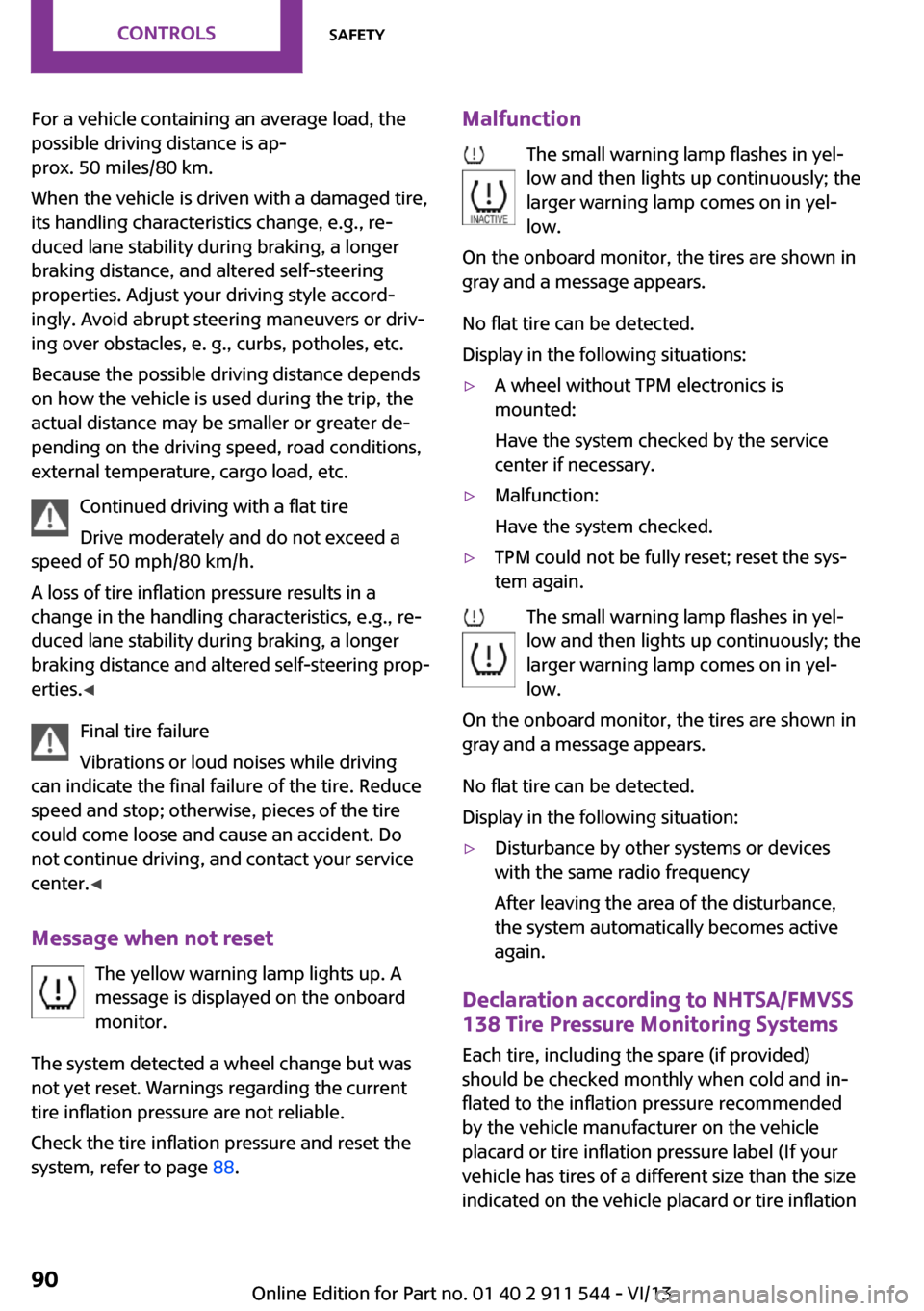
The small warning lamp flashes in yel‐
low and then lights up continuously; the
larger warning lamp comes on in yel‐
low.
On the onboard monitor, the tires are shown in
gray and a message appears.
No flat tire can be detected.
Display in the following situations:▷A wheel without TPM electronics is
mounted:
Have the system checked by the service
center if necessary.▷Malfunction:
Have the system checked.▷TPM could not be fully reset; reset the sys‐
tem again.
The small warning lamp flashes in yel‐
low and then lights up continuously; the
larger warning lamp comes on in yel‐
low.
On the onboard monitor, the tires are shown in
gray and a message appears.
No flat tire can be detected.
Display in the following situation:
▷Disturbance by other systems or devices
with the same radio frequency
After leaving the area of the disturbance,
the system automatically becomes active
again.
Declaration according to NHTSA/FMVSS
138 Tire Pressure Monitoring Systems
Each tire, including the spare (if provided)
should be checked monthly when cold and in‐
flated to the inflation pressure recommended
by the vehicle manufacturer on the vehicle
placard or tire inflation pressure label (If your
vehicle has tires of a different size than the size indicated on the vehicle placard or tire inflation
Seite 90ControlsSafety90
Online Edition for Part no. 01 40 2 911 544 - VI/13
Page 105 of 282
3.Hold the hand-held transmitter of the sys‐
tem to be operated a distance of approx. 1
to 3 in/2.5 to 8 cm away from the buttons
on the interior rearview mirror. The re‐
quired distance depends on the particular
hand-held transmitter.4.Press the button of the desired function on
the hand-held transmitter and the button
being programmed on the interior rearview
mirror simultaneously and hold. The LED on
the interior rearview mirror flashes slowly at
first.5.When the LED flashes more rapidly, release
both buttons. Rapid flashing indicates that
the button on the interior rearview mirror
has been programmed.
If the LED does not flash faster after 60 sec‐
onds, change the distance between the in‐
terior rearview mirror and the hand-held
transmitter and repeat the step. Multiple
trials at different distances may be neces‐
sary. Wait at least 15 seconds between tri‐
als.6.To program additional functions on other
buttons, repeat steps 3 to 5.
The systems can be operated with the buttons
on the interior rearview mirror.
Special characteristics of alternating-
code radio systems
If the system cannot be operated after re‐
peated programming, check whether the sys‐
tem to be operated uses an alternating-code
system.
Read the operating instructions of the system
or press and hold the programmed button on
the interior rearview mirror. If the LED on the
interior rearview mirror flashes rapidly at first
and then lights up continuously for 2 seconds,
the system is equipped with an alternating-
code system. This flashing LED pattern repeats
itself for approx. 20 seconds.
In systems with an alternating-code system, the
universal garage door opener and the system
must be additionally synchronized.
Please obtain additional information on syn‐
chronization in the operating instructions of the
system being set up.
The systems will be easier to synchronize with
the aid of a second person.
Synchronization:1.Park the vehicle within range of the re‐
mote-controlled system.2.Program the corresponding button on the
interior rearview mirror as described.3.Identify and press the synchronization but‐
ton on the system being set up. You have
approx. 30 seconds for the next step.4.Press and hold the button on the interior
rearview mirror for approx. 3 seconds and
then release it. Repeat this step up to three
times if necessary to complete the synchro‐
nization procedure. When synchronization
is completed, the programmed function is
executed.
Reprogramming individual buttons
1.Switch on the ignition.2.Hold the hand-held transmitter at a dis‐
tance of approx. 1 to 3 in/2.5 to 8 cm from
the memory buttons.
The required distance depends on the par‐
ticular hand-held transmitter.3.Press the memory button of the universal
garage door opener.4.If the LED flashes slowly after approx.
20 seconds, press the transmit button on
the hand-held transmitter.5.Release both buttons when the LED flashes
rapidly.
If the LED does not flash rapidly after ap‐
prox. 60 seconds, change the distance and
repeat the step.Seite 105Interior equipmentControls105
Online Edition for Part no. 01 40 2 911 544 - VI/13
Page 106 of 282
Canada: if the LED does not flash rapidly af‐
ter approx. 60 seconds, change the dis‐
tance and repeat the step. If programming
was aborted by the hand-held transmitter,
hold down the memory button and press
and release the button on the hand-held
transmitter several times for 2 seconds.
Controls
Prior to operation
Before operating a unit with the Universal
Garage Door Opener, ensure that there are no
people, animals, or objects in the range of
movement of the system; otherwise, there is a
risk of injury or damage.
Also follow the safety instructions of the hand-
held transmitter. ◀
The system, such as the garage door, can be
operated using the button on the interior rear‐
view mirror with the engine running or the igni‐
tion switched on. When you are within the re‐
ception range of the system, press and hold the
button until the function is initiated. The LED on
the interior rearview mirror lights up continu‐
ously while the radio signal is being transmit‐
ted.
Deleting stored functions
Press the right and left buttons on the interior
rearview mirror simultaneously for approx.
20 seconds until the LED flashes rapidly. All
stored functions are deleted. The functions can‐
not be deleted individually.
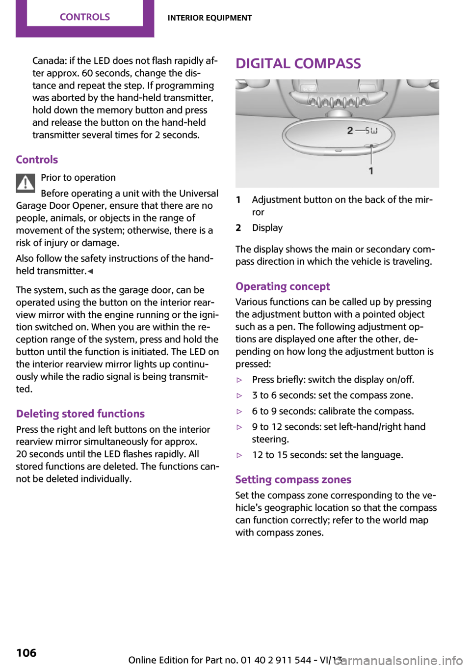
Digital compass1Adjustment button on the back of the mir‐
ror2Display
The display shows the main or secondary com‐
pass direction in which the vehicle is traveling.
Operating concept
Various functions can be called up by pressing
the adjustment button with a pointed object
such as a pen. The following adjustment op‐
tions are displayed one after the other, de‐
pending on how long the adjustment button is
pressed:
▷Press briefly: switch the display on/off.▷3 to 6 seconds: set the compass zone.▷6 to 9 seconds: calibrate the compass.▷9 to 12 seconds: set left-hand/right hand
steering.▷12 to 15 seconds: set the language.
Setting compass zones
Set the compass zone corresponding to the ve‐
hicle's geographic location so that the compass
can function correctly; refer to the world map
with compass zones.
Seite 106ControlsInterior equipment106
Online Edition for Part no. 01 40 2 911 544 - VI/13
Page 149 of 282
SymbolFunction Display traffic bulletins. Open the interactive map. Adjust the map views. Adjust the arrow view. Change the scale.
Changing the map section
"Interactive map"
▷To shift the map: move the MINI joystick in
the required direction.▷To shift the map diagonally: move the
MINI joystick in the required direction and
turn the MINI joystick.
Changing the scale
1. Select the symbol.2.To change the scale: turn the MINI joystick.
Automatically scaled map scale
In the map view facing north, turn the MINI joy‐
stick in any direction until the AUTO is dis‐
played for the scale. The entire route between
the current location and the destination is dis‐
played on the map.
Settings for the map view
The settings are stored for the remote control
currently in use.
1."Navigation"2."Map"3.Open "Options".4."Settings"5.To set the map view:▷"Day/night mode"
Select and create the necessary settings
depending on the light conditions."Traffic conditions/gray map" active:
the setting is disregarded.▷"Traffic conditions/gray map"
The map is optimized for displaying
traffic bulletins.
Symbols for the special destinations are
no longer displayed.
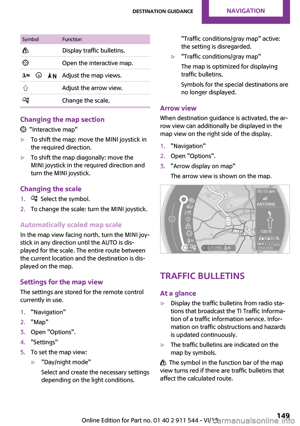
Arrow view
When destination guidance is activated, the ar‐
row view can additionally be displayed in the
map view on the right side of the display.
1."Navigation"2.Open "Options".3."Arrow display on map"
The arrow view is shown on the map.
Traffic bulletins
At a glance
▷Display the traffic bulletins from radio sta‐
tions that broadcast the TI Traffic Informa‐
tion of a traffic information service. Infor‐
mation on traffic obstructions and hazards
is updated continuously.▷The traffic bulletins are indicated on the
map by symbols.
The symbol in the function bar of the map
view turns red if there are traffic bulletins that
affect the calculated route.
Seite 149Destination guidanceNavigation149
Online Edition for Part no. 01 40 2 911 544 - VI/13
Page 156 of 282
ToneVehicle equipmentThis chapter describes all series equipment as
well as country-specific and special equipment
offered for this model series.Therefore, it also
describes equipment that may not be found in
your vehicle, for instance due to the selected
special equipment or the country version. This
also applies to safety-related functions and sys‐
tems.
General information The sound settings are stored for the remote
control currently in use.
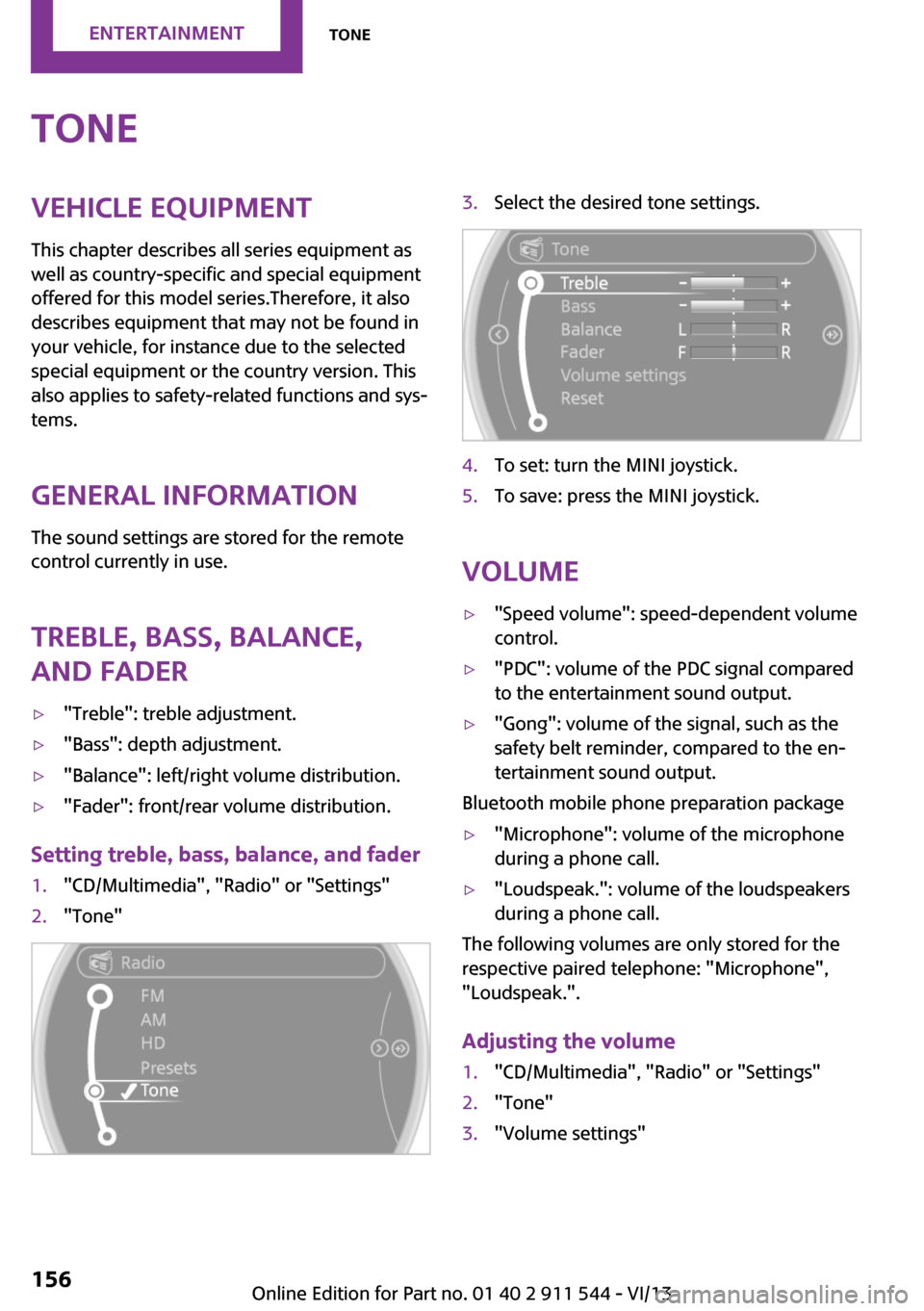
Treble, bass, balance,
and fader▷"Treble": treble adjustment.▷"Bass": depth adjustment.▷"Balance": left/right volume distribution.▷"Fader": front/rear volume distribution.
Setting treble, bass, balance, and fader
1."CD/Multimedia", "Radio" or "Settings"2."Tone"3.Select the desired tone settings.4.To set: turn the MINI joystick.5.To save: press the MINI joystick.
Volume
▷"Speed volume": speed-dependent volume
control.▷"PDC": volume of the PDC signal compared
to the entertainment sound output.▷"Gong": volume of the signal, such as the
safety belt reminder, compared to the en‐
tertainment sound output.
Bluetooth mobile phone preparation package
▷"Microphone": volume of the microphone
during a phone call.▷"Loudspeak.": volume of the loudspeakers
during a phone call.
The following volumes are only stored for the
respective paired telephone: "Microphone",
"Loudspeak.".
Adjusting the volume
1."CD/Multimedia", "Radio" or "Settings"2."Tone"3."Volume settings"Seite 156EntertainmentTone156
Online Edition for Part no. 01 40 2 911 544 - VI/13
Page 157 of 282
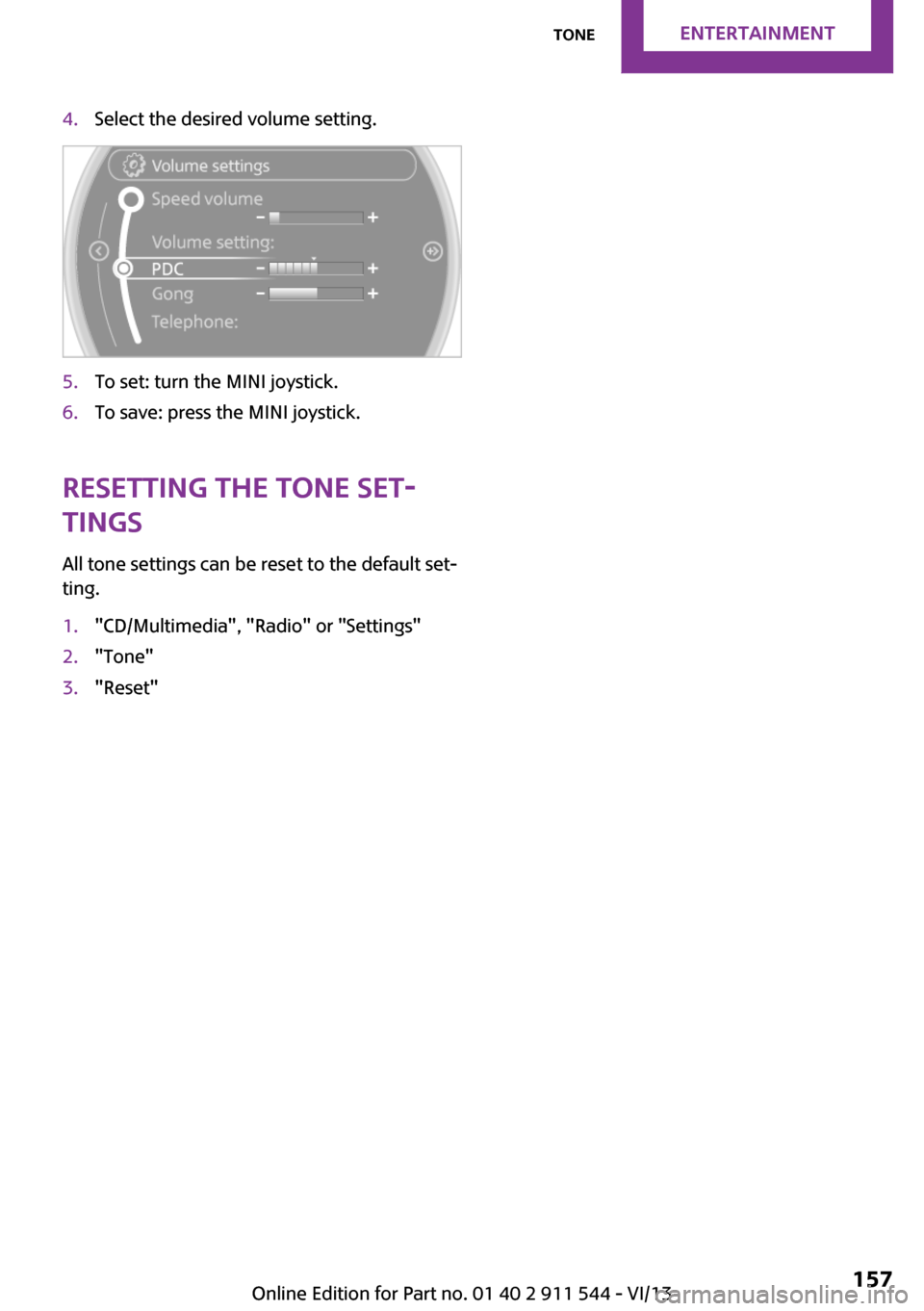
4.Select the desired volume setting.5.To set: turn the MINI joystick.6.To save: press the MINI joystick.
Resetting the tone set‐
tings
All tone settings can be reset to the default set‐
ting.
1."CD/Multimedia", "Radio" or "Settings"2."Tone"3."Reset"Seite 157ToneEntertainment157
Online Edition for Part no. 01 40 2 911 544 - VI/13