engine MINI Paceman 2014 (Mini Connected) Service Manual
[x] Cancel search | Manufacturer: MINI, Model Year: 2014, Model line: Paceman, Model: MINI Paceman 2014Pages: 282, PDF Size: 6.76 MB
Page 193 of 282
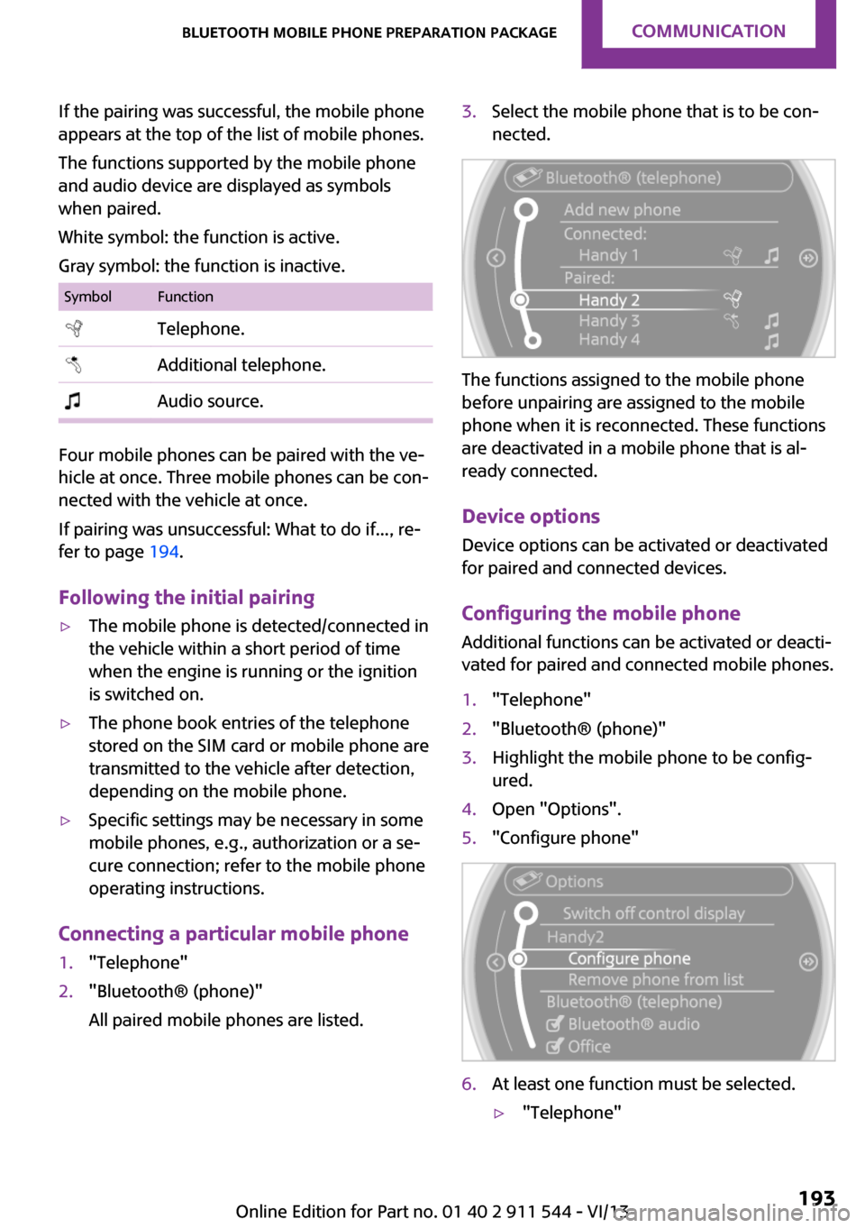
If the pairing was successful, the mobile phone
appears at the top of the list of mobile phones.
The functions supported by the mobile phone
and audio device are displayed as symbols
when paired.
White symbol: the function is active.
Gray symbol: the function is inactive.SymbolFunction Telephone. Additional telephone. Audio source.
Four mobile phones can be paired with the ve‐
hicle at once. Three mobile phones can be con‐
nected with the vehicle at once.
If pairing was unsuccessful: What to do if..., re‐
fer to page 194.
Following the initial pairing
▷The mobile phone is detected/connected in
the vehicle within a short period of time
when the engine is running or the ignition
is switched on.▷The phone book entries of the telephone
stored on the SIM card or mobile phone are
transmitted to the vehicle after detection,
depending on the mobile phone.▷Specific settings may be necessary in some
mobile phones, e.g., authorization or a se‐
cure connection; refer to the mobile phone
operating instructions.
Connecting a particular mobile phone
1."Telephone"2."Bluetooth® (phone)"
All paired mobile phones are listed.3.Select the mobile phone that is to be con‐
nected.
The functions assigned to the mobile phone
before unpairing are assigned to the mobile
phone when it is reconnected. These functions
are deactivated in a mobile phone that is al‐
ready connected.
Device options Device options can be activated or deactivated
for paired and connected devices.
Configuring the mobile phoneAdditional functions can be activated or deacti‐
vated for paired and connected mobile phones.
1."Telephone"2."Bluetooth® (phone)"3.Highlight the mobile phone to be config‐
ured.4.Open "Options".5."Configure phone"6.At least one function must be selected.▷"Telephone"Seite 193Bluetooth mobile phone preparation packageCommunication193
Online Edition for Part no. 01 40 2 911 544 - VI/13
Page 216 of 282

RefuelingVehicle equipmentThis chapter describes all series equipment as
well as country-specific and special equipment
offered for this model series.Therefore, it also
describes equipment that may not be found in
your vehicle, for instance due to the selected
special equipment or the country version. This
also applies to safety-related functions and sys‐
tems.
General information Refuel promptly
At the latest, refuel at a range below
30 miles/50 km; otherwise, the engine function
is not ensured and damage may occur. ◀
Notes Switch off the engine before refueling
Always switch off the engine before refu‐
eling; otherwise, fuel cannot be added to the
tank and a message will be displayed. ◀
Observe when handling fuel▷Take all precautionary measures and
observe all applicable regulations
when handling fuel.▷Do not carry any spare fuel containers in
your vehicle. They can develop a leak and
cause an explosion or cause a fire in the
event of an accident. ◀
Fuel cap
Opening
1.Open fuel filler flap.2.Turn the fuel cap counterclockwise.3.Place the fuel cap in the bracket attached
to the fuel filler flap.
Closing
1.Fit the fuel cap and turn it clockwise until
you clearly hear a click.2.Close the fuel filler flap.
Do not pinch the retaining strap
Do not pinch the retaining strap attached
to the cap; otherwise, the cap cannot be closed
properly and fuel vapors can escape. ◀
A message is displayed if the cap is loose or
missing.
Manually unlocking fuel filler flap In the event of a malfunction, the fuel filler flap
can be released manually:
MINI Countryman:
Seite 216MobilityRefueling216
Online Edition for Part no. 01 40 2 911 544 - VI/13
Page 218 of 282

FuelVehicle equipmentThis chapter describes all series equipment as
well as country-specific and special equipment
offered for this model series.Therefore, it also
describes equipment that may not be found in
your vehicle, for instance due to the selected
special equipment or the country version. This
also applies to safety-related functions and sys‐
tems.
Fuel recommendation GasolineFor the best fuel economy, the gasoline should
be sulfur-free or very low in sulfur content.
Do not use fuels that are labeled at the fuel
pump as containing metals.
Only refuel with lead-free gasoline with‐
out metal additives
Do not refuel with leaded gasoline or gasoline
with metal additives, e. g., manganese or iron;
otherwise, the catalytic converter and other components will be permanently damaged. ◀
Fuels with a maximum ethanol content of
10 %, i.e., E10, may be used for refueling.
The ethanol should fulfill the following quality standards:
US: ASTM 4806–xx
CAN: CGSB-3.511–xx
xx: always adhere to the currently applicable
standard.
Do not refuel with ethanol E85
Do not refuel with E85, i.e., fuel with an
ethanol content of 85 %, or with Flex Fuel, as
this would damage the engine and fuel supply system. ◀The engine is knock controlled. Therefore, you
can refuel with different gasoline qualities.
Gasoline quality
The manufacturer of your MINI recommends:▷AKI 91.▷John Cooper Works AKI 93.
Minimum fuel grade
The manufacturer of your MINI recommends
AKI 89.
Minimum fuel grade
Do not fill up with fuel below the speci‐
fied minimum quality; otherwise, the engine
may not run properly. ◀
If you use gasoline with this minimum AKI rat‐
ing, the engine may produce knocking sounds
when starting at high outside temperatures.
This has no effect on the engine life.
Minimum fuel grade
The use of poor-quality fuels may result in
harmful engine deposits or damage. Addition‐
ally, problems relating to drivability, starting
and stalling, especially under certain environ‐
mental conditions such as high ambient tem‐
perature and high altitude, may occur.
If drivability problems are encountered, we rec‐
ommend switching to a high quality gasoline
brand and a higher octane grade — AKI num‐
ber — for a few tank fills. To avoid harmful en‐
gine deposits, it is highly recommended to pur‐
chase gasoline from BP or Top Tier retailers.
Failure to comply with these recommendations
may result in the need for unscheduled mainte‐
nance. ◀
Seite 218MobilityFuel218
Online Edition for Part no. 01 40 2 911 544 - VI/13
Page 230 of 282
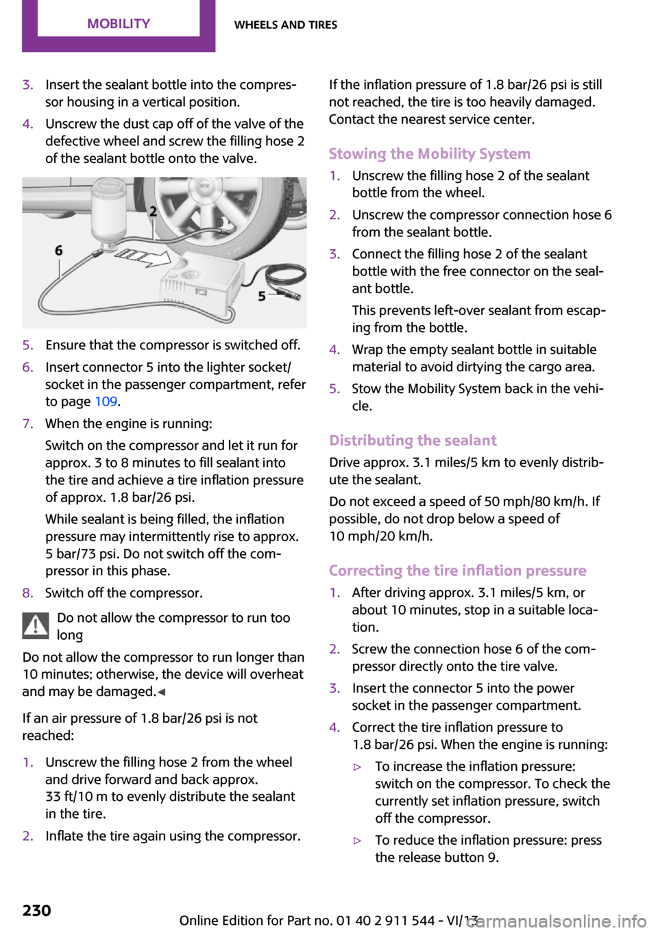
3.Insert the sealant bottle into the compres‐
sor housing in a vertical position.4.Unscrew the dust cap off of the valve of the
defective wheel and screw the filling hose 2
of the sealant bottle onto the valve.5.Ensure that the compressor is switched off.6.Insert connector 5 into the lighter socket/
socket in the passenger compartment, refer
to page 109.7.When the engine is running:
Switch on the compressor and let it run for
approx. 3 to 8 minutes to fill sealant into
the tire and achieve a tire inflation pressure
of approx. 1.8 bar/26 psi.
While sealant is being filled, the inflation
pressure may intermittently rise to approx.
5 bar/73 psi. Do not switch off the com‐
pressor in this phase.8.Switch off the compressor.
Do not allow the compressor to run too
long
Do not allow the compressor to run longer than
10 minutes; otherwise, the device will overheat
and may be damaged. ◀
If an air pressure of 1.8 bar/26 psi is not
reached:
1.Unscrew the filling hose 2 from the wheel
and drive forward and back approx.
33 ft/10 m to evenly distribute the sealant
in the tire.2.Inflate the tire again using the compressor.If the inflation pressure of 1.8 bar/26 psi is still
not reached, the tire is too heavily damaged.
Contact the nearest service center.
Stowing the Mobility System1.Unscrew the filling hose 2 of the sealant
bottle from the wheel.2.Unscrew the compressor connection hose 6
from the sealant bottle.3.Connect the filling hose 2 of the sealant
bottle with the free connector on the seal‐
ant bottle.
This prevents left-over sealant from escap‐
ing from the bottle.4.Wrap the empty sealant bottle in suitable
material to avoid dirtying the cargo area.5.Stow the Mobility System back in the vehi‐
cle.
Distributing the sealant
Drive approx. 3.1 miles/5 km to evenly distrib‐
ute the sealant.
Do not exceed a speed of 50 mph/80 km/h. If
possible, do not drop below a speed of
10 mph/20 km/h.
Correcting the tire inflation pressure
1.After driving approx. 3.1 miles/5 km, or
about 10 minutes, stop in a suitable loca‐
tion.2.Screw the connection hose 6 of the com‐
pressor directly onto the tire valve.3.Insert the connector 5 into the power
socket in the passenger compartment.4.Correct the tire inflation pressure to
1.8 bar/26 psi. When the engine is running:▷To increase the inflation pressure:
switch on the compressor. To check the
currently set inflation pressure, switch
off the compressor.▷To reduce the inflation pressure: press
the release button 9.Seite 230MobilityWheels and tires230
Online Edition for Part no. 01 40 2 911 544 - VI/13
Page 232 of 282
Engine compartmentVehicle equipment
This chapter describes all series equipment as
well as country-specific and special equipment
offered for this model series.Therefore, it alsodescribes equipment that may not be found in
your vehicle, for instance due to the selected
special equipment or the country version. This
also applies to safety-related functions and sys‐
tems.
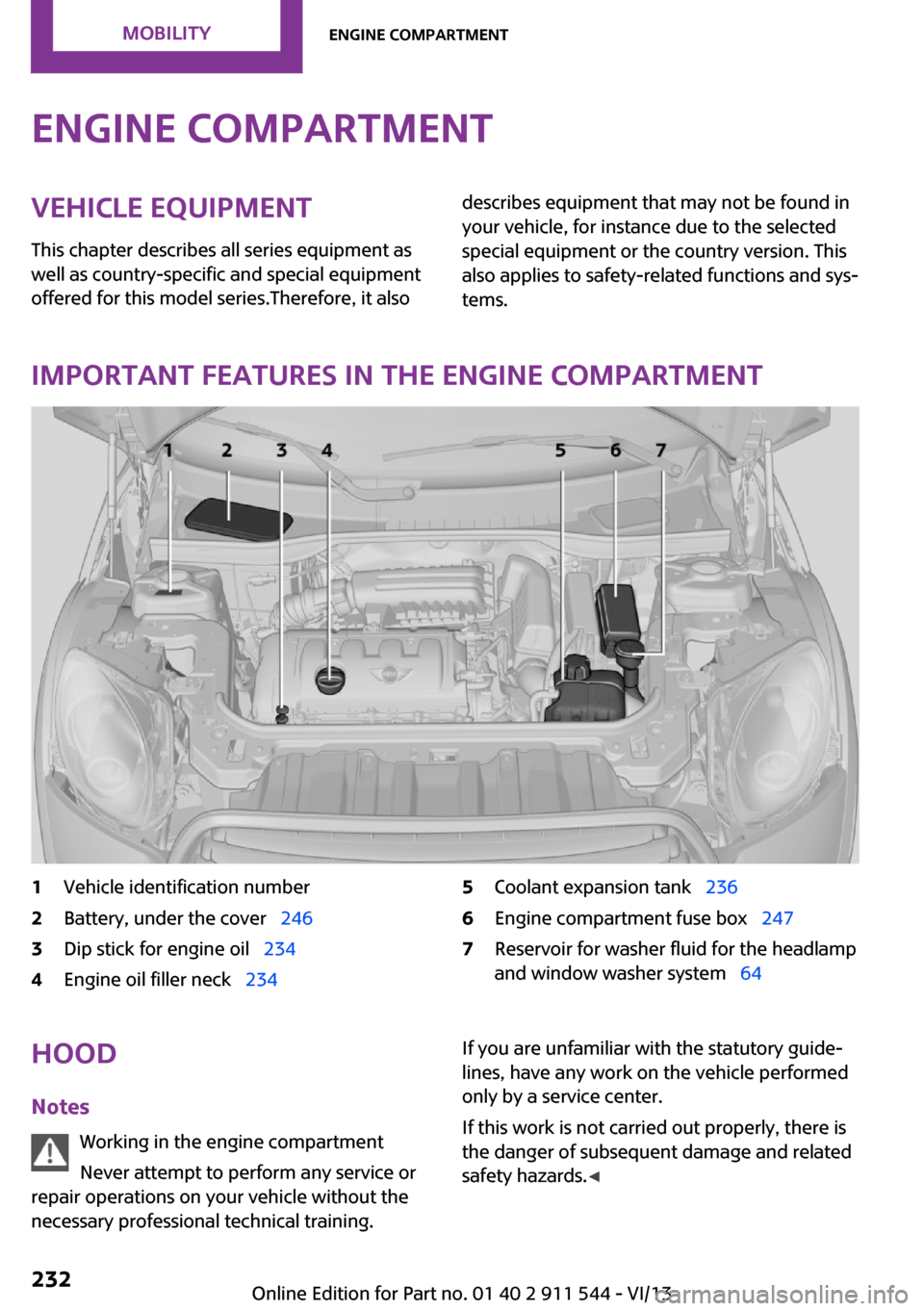
Important features in the engine compartment
1Vehicle identification number2Battery, under the cover 2463Dip stick for engine oil 2344Engine oil filler neck 2345Coolant expansion tank 2366Engine compartment fuse box 2477Reservoir for washer fluid for the headlamp
and window washer system 64Hood
Notes Working in the engine compartment
Never attempt to perform any service or
repair operations on your vehicle without the
necessary professional technical training.If you are unfamiliar with the statutory guide‐
lines, have any work on the vehicle performed
only by a service center.
If this work is not carried out properly, there is
the danger of subsequent damage and related
safety hazards. ◀Seite 232MobilityEngine compartment232
Online Edition for Part no. 01 40 2 911 544 - VI/13
Page 233 of 282

To avoid damage, make sure that the
wiper arms are resting against the wind‐
shield before you open the engine compart‐
ment. Do not open the engine hood before the
engine has cooled down; otherwise, injuries
may result. ◀
Unlocking and opening the hood1.Pull the lever.2.Lift the hood all the way.3.Press the release handle and open the
hood.
Danger of injury when the hood is open
There is a danger of injury from protrud‐
ing parts when the hood is open. ◀
Closing the hood
Close the hood from a height of ap‐
prox. 16 in/40 cm with momentum. It must be
clearly heard to engage.
Hood open when driving
If you see any signs that the hood is not
completely closed while driving, pull over im‐
mediately and close it securely. ◀
Danger of pinching
Make sure that the closing path of the
hood is clear; otherwise, injuries may result. ◀
Seite 233Engine compartmentMobility233
Online Edition for Part no. 01 40 2 911 544 - VI/13
Page 234 of 282

Engine oilVehicle equipment
This chapter describes all series equipment as
well as country-specific and special equipment
offered for this model series.Therefore, it also
describes equipment that may not be found in
your vehicle, for instance due to the selected
special equipment or the country version. This
also applies to safety-related functions and sys‐
tems.
Engine oil General information
Engine oil consumption depends on the driving
style and the conditions of use. A highly sporty
driving style, for example, results in considera‐
bly higher engine oil consumption.
Therefore, regularly check the engine oil level
after refueling.
Checking the oil level with a dip stick1.Park the vehicle on level ground when the
engine is at operating temperature, i.e., af‐
ter driving continuously for at least
6 2 miles/10 km.2.Switch the engine off.3.After approx. 5 minutes, pull out the dip
stick and wipe it off with a lint-free cloth,
paper towel, etc.4.Carefully insert the dip stick all the way into
the measuring tube and pull it out again.The oil level must be between the two
marks on the dip stick.
The oil quantity between the two marks on the
dip stick equals approx. 1 US quart/1 liter.
Do not exceed the high mark.
Do not exceed the high mark of the dip
stick. Overfilling oil damages the engine. ◀
Adding engine oil
Filler neck
Add a maximum quantity of 1 US quart/1 liter
of oil only after the corresponding message ap‐
pears on the Control Display or, in diesel en‐
gines, after the oil level is just above the low
mark of the dip stick, refer to page 234.
Add oil promptly
Add oil within the next 30 miles/50 km;
otherwise, engine damage could result. ◀
Seite 234MobilityEngine oil234
Online Edition for Part no. 01 40 2 911 544 - VI/13
Page 235 of 282
Too much engine oil
Have the vehicle checked immediately;
otherwise, surplus oil can lead to engine dam‐
age. ◀
Protect children
Keep oil, grease, etc., out of reach of chil‐
dren and heed the warnings on the containers
to prevent health risks. ◀
Oil types for refilling
Notes No oil additives
Do not use oil additives as these may
cause engine damage. ◀
Viscosity classes of engine oils
When selecting an engine oil, ensure that
the engine oil belongs to one of the SAE viscos‐
ity classes 0W-40, 0W-30, 5W-40, or 5W-30, or
malfunctions or engine damage may occur. ◀
The engine oil quality is critical for the life of the
engine.
Due to national regulations, some oil types are
not available in every country.
Approved oil typesGasoline engineBMW High Performance SAE 5W-30BMW Longlife-01BMW Longlife-01 FE
Further information on approved oil types can
be obtained from the service center.
Alternative oil types
If the approved engine oils are not available, up
to 1 US quart/1 liter of an oil with the following
specification can be used:
Gasoline engineAPI SM or a higher quality standard
Oil change
An oil change should be carried out by the serv‐
ice center only.
Seite 235Engine oilMobility235
Online Edition for Part no. 01 40 2 911 544 - VI/13
Page 236 of 282
CoolantVehicle equipment
This chapter describes all series equipment as
well as country-specific and special equipment
offered for this model series.Therefore, it also
describes equipment that may not be found in
your vehicle, for instance due to the selected
special equipment or the country version. This
also applies to safety-related functions and sys‐
tems.
General information Danger of burns from hot engine
Do not open the cooling system while the
engine is hot; otherwise, escaping coolant may
cause burns. ◀
Suitable additives
Only use suitable additives; otherwise,
engine damage may occur. The additives are
harmful to your health. ◀
Coolant consists of water and additives.
Not all commercially available additives are
suitable for your MINI vehicle. Ask your service
center for suitable additives.
Coolant temperature
If the coolant and therefore the engine over‐
heat, a warning lamp lights up. A message ap‐
pears on the Control Display.
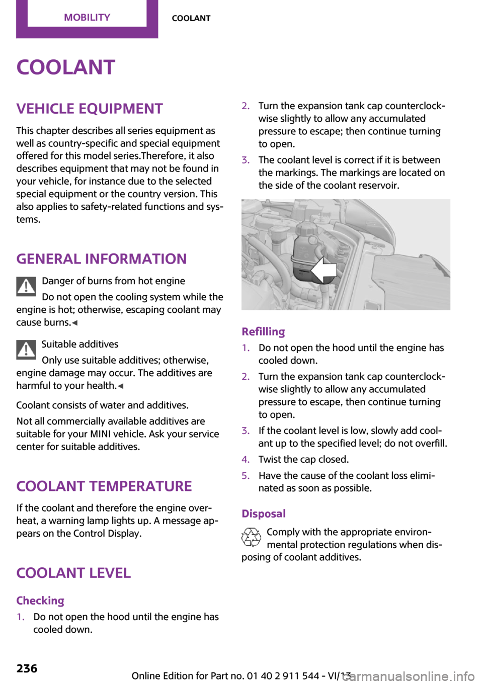
Coolant level Checking1.Do not open the hood until the engine has
cooled down.2.Turn the expansion tank cap counterclock‐
wise slightly to allow any accumulated
pressure to escape; then continue turning
to open.3.The coolant level is correct if it is between
the markings. The markings are located on
the side of the coolant reservoir.
Refilling
1.Do not open the hood until the engine has
cooled down.2.Turn the expansion tank cap counterclock‐
wise slightly to allow any accumulated
pressure to escape, then continue turning
to open.3.If the coolant level is low, slowly add cool‐
ant up to the specified level; do not overfill.4.Twist the cap closed.5.Have the cause of the coolant loss elimi‐
nated as soon as possible.
Disposal
Comply with the appropriate environ‐mental protection regulations when dis‐
posing of coolant additives.
Seite 236MobilityCoolant236
Online Edition for Part no. 01 40 2 911 544 - VI/13
Page 238 of 282

Socket for OBD Onboard
Diagnosis
Socket for Onboard Diagnosis
The socket for Onboard Diagnosis may
only be used by the service center, by work‐
shops that operate according to the specifica‐
tions of the vehicle manufacturer with appro‐
priately trained personnel, and by other
authorized persons. Otherwise, its use may
lead to vehicle malfunctions. ◀
Primary components in the vehicle emissions
can be checked via the OBD socket using a de‐
vice.
Emissions The warning lamps light up. The vehicle
is producing higher emissions. You can
continue your journey, but moderate
your speed and exercise due caution. Have the
vehicle checked as soon as possible.
Under certain circumstances, one of the lamps
flashes or lights up continuously. This indicates
that there is excessive misfiring or a malfunc‐
tion in the engine. If this happens, reduce the
vehicle speed and drive to the next service cen‐
ter promptly. Serious engine misfiring within a
brief period can seriously damage emission
control components, in particular the catalytic
converter. In addition, the mechanical engine
components may become damaged.
If the fuel filler cap is not properly tight‐
ened, the OBD system may conclude
that fuel vapor is escaping; this will cause a dis‐
play to light up. If the filler cap is then tight‐
ened, the display should go out in a few days.Seite 238MobilityMaintenance238
Online Edition for Part no. 01 40 2 911 544 - VI/13