maintenance MINI Paceman 2014 Owner's Manual (Mini Connected)
[x] Cancel search | Manufacturer: MINI, Model Year: 2014, Model line: Paceman, Model: MINI Paceman 2014Pages: 282, PDF Size: 6.76 MB
Page 5 of 282
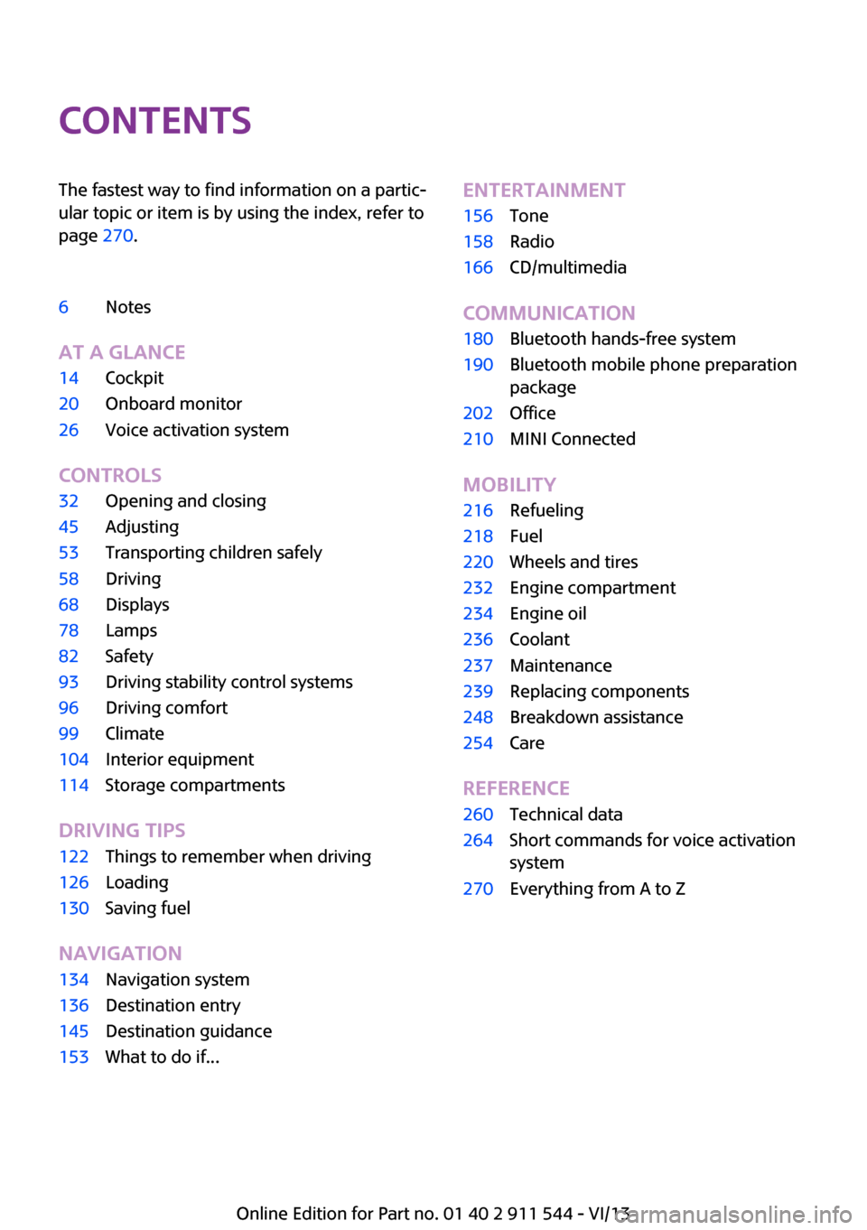
ContentsThe fastest way to find information on a partic‐
ular topic or item is by using the index, refer to
page 270.6Notes
At a glance
14Cockpit20Onboard monitor26Voice activation system
Controls
32Opening and closing45Adjusting53Transporting children safely58Driving68Displays78Lamps82Safety93Driving stability control systems96Driving comfort99Climate104Interior equipment114Storage compartments
Driving tips
122Things to remember when driving126Loading130Saving fuel
Navigation
134Navigation system136Destination entry145Destination guidance153What to do if...Entertainment156Tone158Radio166CD/multimedia
Communication
180Bluetooth hands-free system190Bluetooth mobile phone preparation
package202Office210MINI Connected
Mobility
216Refueling218Fuel220Wheels and tires232Engine compartment234Engine oil236Coolant237Maintenance239Replacing components248Breakdown assistance254Care
Reference
260Technical data264Short commands for voice activation
system270Everything from A to Z
Online Edition for Part no. 01 40 2 911 544 - VI/13
Page 7 of 282
For your own safety
Warranty Your vehicle is technically configured for the
operating conditions and registration require‐
ments applying in the country of first delivery
— homologation. If your vehicle is to be oper‐
ated in a different country it might be neces‐
sary to adapt your vehicle to potentially differ‐
ing operating conditions and permit
requirements. If your vehicle does not comply
with the homologation requirements in a cer‐
tain country you cannot lodge warranty claims
for your vehicle there. Further information can
be obtained from your Service Centre.
Maintenance and repairs Advanced technology, e.g., the use of modern
materials and high-performance electronics,
requires suitable maintenance and repair
methods.
Therefore, have this work performed only by a
MINI service center or a workshop that works
according to MINI repair procedures with ap‐
propriately trained personnel.
If this work is not carried out properly, there is
the danger of subsequent damage and related
safety hazards.
Parts and accessories
For your own safety, use genuine parts and ac‐
cessories approved by the manufacturer of the
MINI. When you purchase accessories tested
and approved by the manufacturer of the MINI
and Original MINI Parts, you simultaneously ac‐
quire the assurance that they have been thor‐
oughly tested by the manufacturer of the MINI
to ensure optimum performance when instal‐
led on your vehicle. The manufacturer of the
MINI warrants these parts to be free from de‐
fects in material and workmanship. The manu‐
facturer of the MINI will not accept any liability
for damage resulting from installation of parts
and accessories not approved by the manufac‐turer of the MINI. The manufacturer of the MINI
cannot test every product made by other man‐
ufacturers to verify if it can be used on a MINI
safely and without risk to either the vehicle, its
operation, or its occupants. Original MINI Parts,
MINI Accessories and other products approved
by the manufacturer of the MINI, together with
professional advice on using these items, are
available from all MINI Dealers. Installation and
operation of non-MINI approved accessories
such as alarms, radios, amplifiers, radar detec‐
tors, wheels, suspension components, brake
dust shields, telephones, including operation of
any mobile phone from within the vehicle with‐
out using an externally mounted antenna, or
transceiver equipment, for instance, CBs,
walkie-talkies, ham radios or similar accesso‐
ries, may cause extensive damage to the vehi‐
cle, compromise its safety, interfere with the
vehicle's electrical system or affect the validity
of the MINI Limited Warranty. See your MINI
Dealer for additional information. Maintenance,
replacement, or repair of the emission control
devices and systems may be performed by any
automotive repair establishment or individual
using any certified automotive part.
California Proposition 65 Warning
California laws require us to state the following
warning:
Engine exhaust and a wide variety of automo‐
bile components and parts, including compo‐
nents found in the interior furnishings in a vehi‐
cle, contain or emit chemicals known to the
State of California to cause cancer and birth de‐
fects and reproductive harm. In addition, cer‐
tain fluids contained in vehicles and certain
products of component wear contain or emit
chemicals known to the State of California to
cause cancer and birth defects or other repro‐
ductive harm. Battery posts, terminals and re‐
lated accessories contain lead and lead com‐
pounds. Wash your hands after handling. Used
engine oil contains chemicals that have caused
cancer in laboratory animals. Always protectSeite 7Notes7
Online Edition for Part no. 01 40 2 911 544 - VI/13
Page 8 of 282
your skin by washing thoroughly with soap and
water.
Service and warranty
We recommend that you read this publication
thoroughly. Your vehicle is covered by the fol‐
lowing warranties:▷New Vehicle Limited Warranty.▷Rust Perforation Limited Warranty.▷Federal Emissions System Defect Warranty.▷Federal Emissions Performance Warranty.▷California Emission Control System Limited
Warranty.
Detailed information about these warranties is
listed in the Service and Warranty Information
Booklet for US models or in the Warranty and
Service Guide Booklet for Canadian models.
Your vehicle has been specifically adapted and
designed to meet the particular operating con‐
ditions and homologation requirements in your
country and continental region in order to de‐
liver the full driving pleasure while the vehicle is
operated under those conditions. If you wish to
operate your vehicle in another country or re‐
gion, you may be required to adapt your vehi‐
cle to meet different prevailing operating con‐
ditions and homologation requirements. You
should also be aware of any applicable war‐
ranty limitations or exclusions for such country
or region. In such case, please contact Cus‐
tomer Relations for further information.
Maintenance
Maintain the vehicle regularly to sustain the
road safety, operational reliability and the New
Vehicle Limited Warranty.
Specifications for required maintenance meas‐
ures:
▷MINI Maintenance system▷Service and Warranty Information Booklet
for US models▷Warranty and Service Guide Booklet for
Canadian modelsIf the vehicle is not maintained according to
these specifications, this could result in serious
damage to the vehicle. Such damage is not
covered by the MINI New Vehicle Limited War‐
ranty.
Data memory
Numerous electronic components in your vehi‐
cle contain data memories that store technical
information on the vehicle condition, events and faults, either temporarily or permanently.This technical information generally documents
the state of a component, a module, a system
or the environment.▷Operating conditions of system compo‐
nents, such as filling levels.▷Status messages from the vehicle and its in‐
dividual components, such as wheel rpm/
speed, motion delay, transverse accelera‐
tion.▷Malfunctions and defects in important sys‐
tem components, such as lights and brakes.▷Vehicle responses to special driving situa‐
tions, such as airbag deployment, use of
the stability control systems.▷Ambient conditions, such as the tempera‐
ture.
These data are of a technical nature only and
are used to detect and eliminate faults and to
optimize vehicle functions. Travel profiles of
routes driven with the vehicle cannot be cre‐
ated from these data. If services are used, for
instance in the event of repairs, service proc‐
esses, warranty cases, quality assurance, etc.,
this technical information can be read out from
the event and fault data memories by service
personnel, including the manufacturer, using
special diagnosis tools. This service personnel
can provide you with more information if
needed. After troubleshooting, the information
in the fault memory is cleared or overwritten
continuously.
Seite 8Notes8
Online Edition for Part no. 01 40 2 911 544 - VI/13
Page 74 of 282
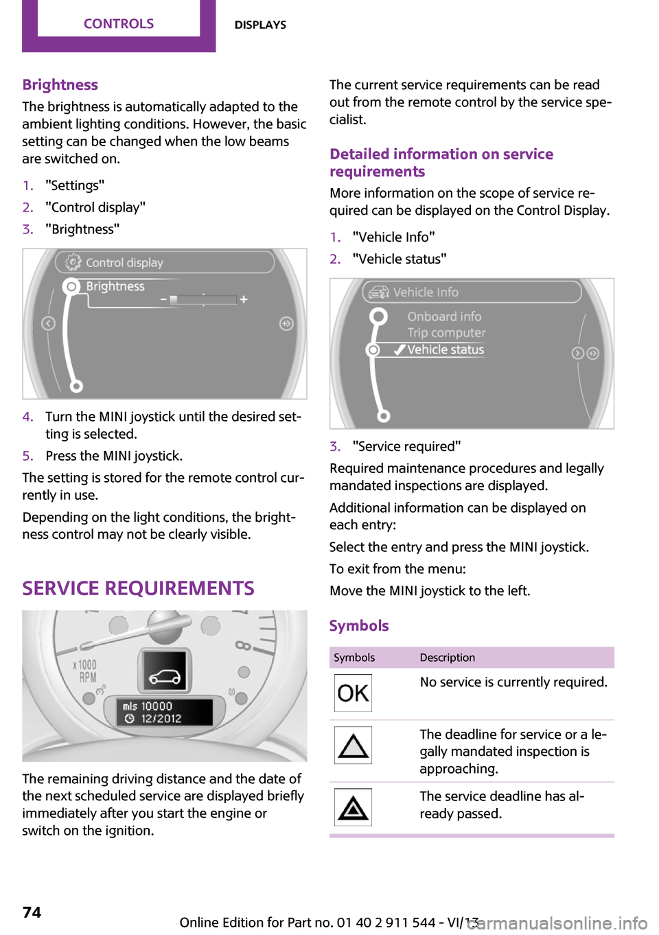
Brightness
The brightness is automatically adapted to the
ambient lighting conditions. However, the basic
setting can be changed when the low beams
are switched on.1."Settings"2."Control display"3."Brightness"4.Turn the MINI joystick until the desired set‐
ting is selected.5.Press the MINI joystick.
The setting is stored for the remote control cur‐
rently in use.
Depending on the light conditions, the bright‐
ness control may not be clearly visible.
Service requirements
The remaining driving distance and the date of
the next scheduled service are displayed briefly
immediately after you start the engine or
switch on the ignition.
The current service requirements can be read
out from the remote control by the service spe‐
cialist.
Detailed information on service
requirements
More information on the scope of service re‐
quired can be displayed on the Control Display.1."Vehicle Info"2."Vehicle status"3."Service required"
Required maintenance procedures and legally
mandated inspections are displayed.
Additional information can be displayed on
each entry:
Select the entry and press the MINI joystick.
To exit from the menu:
Move the MINI joystick to the left.
Symbols
SymbolsDescriptionNo service is currently required.The deadline for service or a le‐
gally mandated inspection is
approaching.The service deadline has al‐
ready passed.Seite 74ControlsDisplays74
Online Edition for Part no. 01 40 2 911 544 - VI/13
Page 91 of 282
pressure label, you should determine the
proper tire inflation pressure for those tires.).
As an added safety feature, your vehicle has
been equipped with a tire pressure monitoring
system (TPMS) that illuminates a low tire pres‐
sure telltale when one or more of your tires is
significantly under-inflated. Accordingly, when
the low tire pressure telltale illuminates, you
should stop and check your tires as soon as
possible, and inflate them to the proper pres‐
sure. Driving on a significantly under-inflated
tire causes the tire to overheat and can lead to
tire failure. Under-inflation also reduces fuel ef‐
ficiency and tire tread life, and may affect the
vehicle's handling and stopping ability.
Please note that the TPMS is not a substitute for
proper tire maintenance, and it is the driver's
responsibility to maintain correct tire pressure,
even if under-inflation has not reached the
level to trigger illumination of the TPMS low tire
pressure telltale.
Your vehicle has also been equipped with a
TPMS malfunction indicator to indicate when
the system is not operating properly. The TPMS
malfunction indicator is combined with the low
tire pressure telltale. When the system detects
a malfunction, the telltale will flash for approxi‐
mately one minute and then remain continu‐
ously illuminated. This sequence will continue
upon subsequent vehicle startups as long as
the malfunction exists. When the malfunction
indicator is illuminated, the system may not be
able to detect or signal low tire pressure as in‐
tended. TPMS malfunctions may occur for a va‐
riety of reasons, including the installation of re‐
placement or alternate tires or wheels on the
vehicle that prevent the TPMS from functioning
properly. Always check the TPMS malfunction
telltale after replacing one or more tires or
wheels on your vehicle to ensure that the re‐
placement or alternate tires and wheels allow
the TPMS to continue to function properly.Speed limit
The concept
Enter a speed for which a Check Control mes‐
sage will be displayed when the speed is
reached. This enables you to receive warnings if
you exceed a speed limit in an urban area, for
example.
You are only warned of reaching this speed a
second time if your vehicle speed falls below it
again by at least 3 mph/5 km/h.
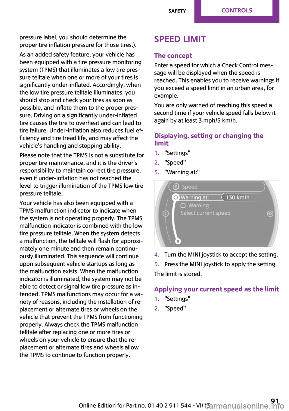
Displaying, setting or changing the
limit1."Settings"2."Speed"3."Warning at:"4.Turn the MINI joystick to accept the setting.5.Press the MINI joystick to apply the setting.
The limit is stored.
Applying your current speed as the limit
1."Settings"2."Speed"Seite 91SafetyControls91
Online Edition for Part no. 01 40 2 911 544 - VI/13
Page 101 of 282
Microfilter
The microfilter traps dust and pollen. The mi‐
crofilter is changed by the service center during
routine maintenance work.
Microfilter/activated-charcoal filter
The microfilter traps dust and pollen. The acti‐
vated-charcoal filter provides additional protec‐tion by filtering gaseous pollutants from the
outside air. The service center replaces this
combined filter during routine maintenance.
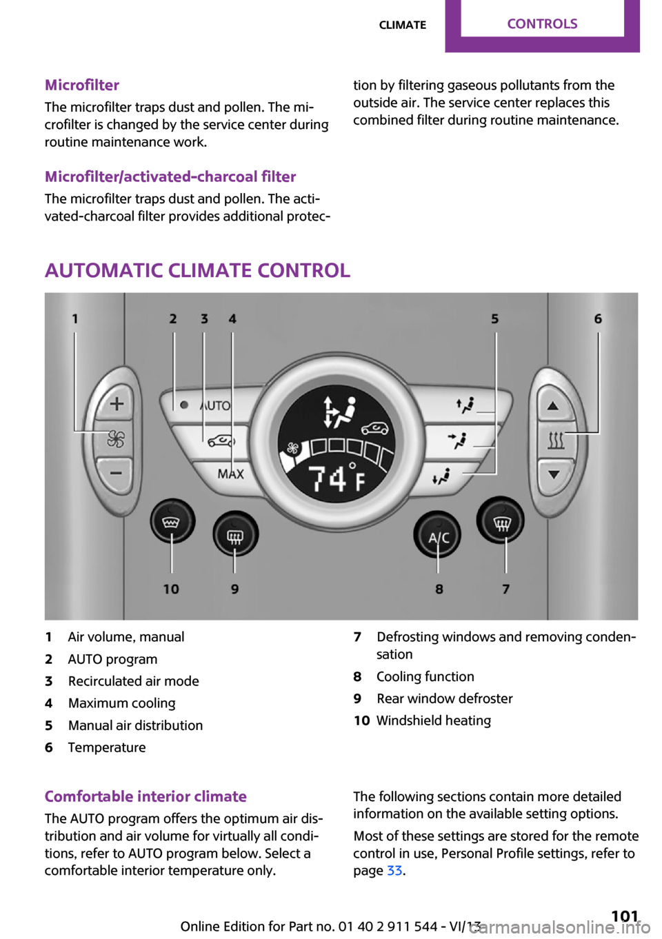
Automatic climate control
1Air volume, manual2AUTO program3Recirculated air mode4Maximum cooling5Manual air distribution6Temperature7Defrosting windows and removing conden‐
sation8Cooling function9Rear window defroster10Windshield heatingComfortable interior climate
The AUTO program offers the optimum air dis‐tribution and air volume for virtually all condi‐
tions, refer to AUTO program below. Select a
comfortable interior temperature only.The following sections contain more detailed
information on the available setting options.
Most of these settings are stored for the remote
control in use, Personal Profile settings, refer to
page 33.Seite 101ClimateControls101
Online Edition for Part no. 01 40 2 911 544 - VI/13
Page 103 of 282
When switching between different temperature
settings in rapid succession, the automatic cli‐
mate control does not have sufficient time to
adjust the set temperature.
Rear window defroster The rear window defroster
switches off automatically after a
certain period of time.
Depending on the vehicle equipment, upper
wires are used as an antenna and are not part
of the rear window defroster.
Defrosting and defogging windows Quickly removes ice and con‐densation from the windshieldand front side windows. For this
purpose, also switch on the cool‐
ing function.
The windshield heating switches on automati‐
cally.
Windshield heating The windshield heating switches
off automatically after some
time.
Cooling function The cooling function cools and
dehumidifies the incoming air
before reheating it as required,
according to the temperature
setting. The passenger compart‐
ment can only be cooled with the engine run‐ ning.
The cooling function helps to prevent conden‐
sation on the windows or to remove it quickly.Depending on the weather, the windshield may
fog up briefly when the engine is started. Recir‐
culated air mode is switched on automatically if
necessary.
The cooling function is switched on automati‐
cally when the AUTO button is pressed.
Microfilter/activated-charcoal filter
The microfilter traps dust and pollen. The acti‐
vated-charcoal filter provides additional protec‐
tion by filtering gaseous pollutants from the
outside air. The service center replaces this
combined filter during routine maintenance.
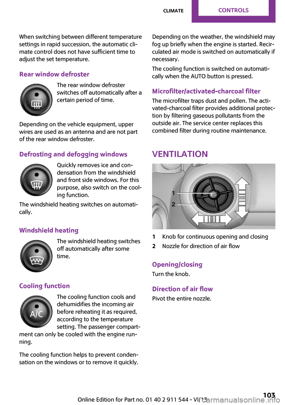
Ventilation1Knob for continuous opening and closing2Nozzle for direction of air flow
Opening/closingTurn the knob.
Direction of air flow Pivot the entire nozzle.
Seite 103ClimateControls103
Online Edition for Part no. 01 40 2 911 544 - VI/13
Page 131 of 282
Switch off the engine during longer
stops
Switch off the engine during longer stops, e.g.,
at traffic lights, railroad crossings or in traffic
congestion.
Fuel savings are already achieved after the en‐
gine is turned off for as little as 4 seconds.
Automatic Engine Start/Stop Function
The Automatic Engine Start/Stop Function auto‐
matically switches the engine off during a stop.
If the engine is stopped and then started again,
fuel consumption and emissions drop com‐
pared to an engine that runs permanently.
Stopping the engine even for just a few sec‐
onds can result in savings.
In addition, fuel consumption depends on other
factors as well, such as driving style, road con‐
ditions, maintenance, and environmental fac‐
tors.
Switch off any functions that are not currently needed
Functions such as seat heating and the rear
window defroster require a lot of energy and
consume additional fuel, especially in city and
stop-and-go traffic.
Therefore, switch off these functions if they are
not actually needed.
Have maintenance carried out
Have vehicles maintained regularly to achieve
optimal vehicle economy and operating life.
Have the maintenance carried out by the serv‐
ice center.
Please also note the MINI maintenance system,
refer to page 237.Seite 131Saving fuelDriving tips131
Online Edition for Part no. 01 40 2 911 544 - VI/13
Page 220 of 282
Wheels and tiresVehicle equipment
This chapter describes all series equipment as
well as country-specific and special equipment
offered for this model series.Therefore, it also
describes equipment that may not be found in
your vehicle, for instance due to the selected
special equipment or the country version. This
also applies to safety-related functions and sys‐
tems.
Tire inflation pressure Safety information
It is not merely the tires' service life, but also
driving comfort and, to a great extent, driving
safety that depend on the condition of the tires
and the maintenance of the specified tire pres‐
sure.
Checking the pressure Check the tire inflation pressure regularly
Regularly check the tire inflation pressure
and correct it as needed: at least twice a month
and before a long trip. If you fail to observe this
precaution, you may be driving on tires with in‐
correct tire pressures, a condition that may not
only compromise your vehicle's driving stabil‐
ity, but also lead to tire damage and the risk of
an accident.
Do not drive with depressurized or flat tires, ex‐
cept for run-flat tires. A flat tire will seriously
impair your vehicle's handling and braking re‐
sponse. Attempts to drive on a flat tire can lead
to a loss of control over the vehicle. ◀
Only check the tire inflation pressure when the
tires are cold. This means after a maximum of
1.25 miles/2 km driving or when the vehicle
has been parked for at least 2 hours. When thetires are warm, the tire inflation pressure is
higher.
After correcting the tire inflation pressure, reset
the Tire Pressure Monitor, refer to page 88
or reinitialize the Flat Tire Monitor, refer to
page 86.
To check the inflation pressure, there is a valve
extension behind the bumper.
Pressure specifications
The tables below provide all the correct infla‐
tion pressures for the specified tire sizes at am‐
bient temperature.
The inflation pressures apply to the tire sizes
approved and tire brands recommended by the
manufacturer of the MINI; a list of these is
available from the service center.
For correct identification of the right tire infla‐
tion pressures, observe the following:▷Tire sizes of your vehicle▷Maximum allowable driving speed
Tire inflation pressures for driving up to
100 mph or 160 km/h
For normal driving up to 100 mph/160 km/h,
adjust pressures to the respective tire inflation
pressures listed on the following pages in the
column for traveling speeds up to 100 mph/
160 km/h to achieve optimum driving comfort.
These tire inflation pressures can also be found
on the driver's side door pillar when the driver's
door is open.
Seite 220MobilityWheels and tires220
Online Edition for Part no. 01 40 2 911 544 - VI/13
Page 237 of 282
MaintenanceVehicle equipment
This chapter describes all series equipment as
well as country-specific and special equipment
offered for this model series.Therefore, it also
describes equipment that may not be found in
your vehicle, for instance due to the selected
special equipment or the country version. This
also applies to safety-related functions and sys‐
tems.
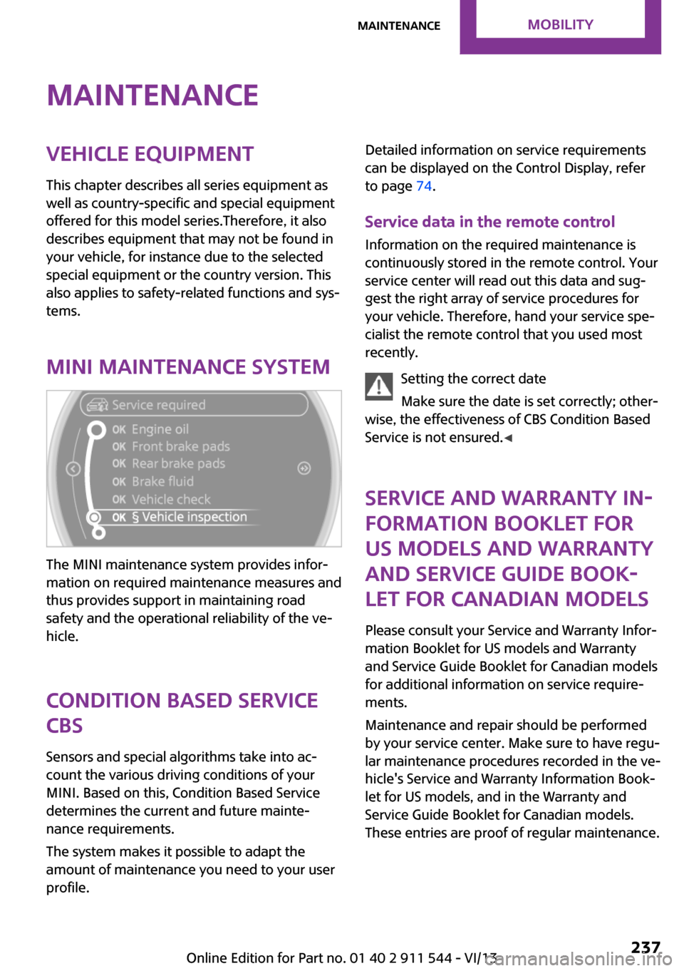
MINI maintenance system
The MINI maintenance system provides infor‐
mation on required maintenance measures and
thus provides support in maintaining road
safety and the operational reliability of the ve‐
hicle.
Condition Based Service
CBS
Sensors and special algorithms take into ac‐
count the various driving conditions of your
MINI. Based on this, Condition Based Service
determines the current and future mainte‐
nance requirements.
The system makes it possible to adapt the
amount of maintenance you need to your user
profile.
Detailed information on service requirements
can be displayed on the Control Display, refer
to page 74.
Service data in the remote control
Information on the required maintenance is continuously stored in the remote control. Your
service center will read out this data and sug‐
gest the right array of service procedures for
your vehicle. Therefore, hand your service spe‐
cialist the remote control that you used most
recently.
Setting the correct date
Make sure the date is set correctly; other‐
wise, the effectiveness of CBS Condition Based
Service is not ensured. ◀
Service and Warranty In‐
formation Booklet for
US models and Warranty and Service Guide Book‐
let for Canadian models
Please consult your Service and Warranty Infor‐
mation Booklet for US models and Warranty
and Service Guide Booklet for Canadian models
for additional information on service require‐
ments.
Maintenance and repair should be performed
by your service center. Make sure to have regu‐
lar maintenance procedures recorded in the ve‐
hicle's Service and Warranty Information Book‐
let for US models, and in the Warranty and
Service Guide Booklet for Canadian models.
These entries are proof of regular maintenance.Seite 237MaintenanceMobility237
Online Edition for Part no. 01 40 2 911 544 - VI/13