steering MINI Paceman 2014 Owner's Manual (Mini Connected)
[x] Cancel search | Manufacturer: MINI, Model Year: 2014, Model line: Paceman, Model: MINI Paceman 2014Pages: 282, PDF Size: 6.76 MB
Page 14 of 282
CockpitVehicle equipment
This chapter describes all series equipment as
well as country-specific and special equipment
offered for this model series.Therefore, it alsodescribes equipment that may not be found in
your vehicle, for instance due to the selected
special equipment or the country version. This
also applies to safety-related functions and sys‐
tems.
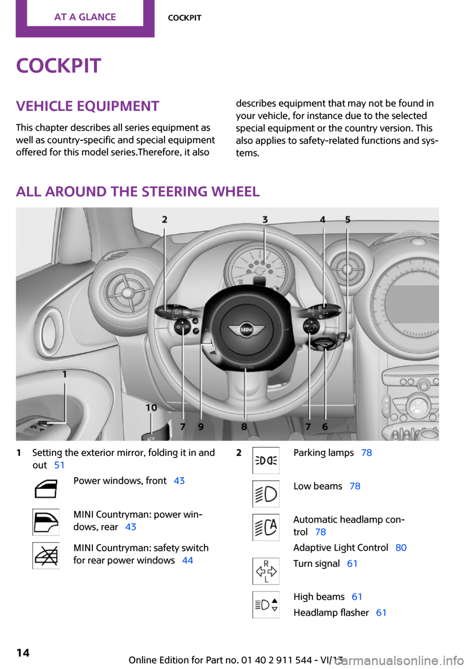
All around the steering wheel
1Setting the exterior mirror, folding it in and
out 51Power windows, front 43MINI Countryman: power win‐
dows, rear 43MINI Countryman: safety switch
for rear power windows 442Parking lamps 78Low beams 78Automatic headlamp con‐
trol 78
Adaptive Light Control 80Turn signal 61High beams 61
Headlamp flasher 61Seite 14At a glanceCockpit14
Online Edition for Part no. 01 40 2 911 544 - VI/13
Page 15 of 282
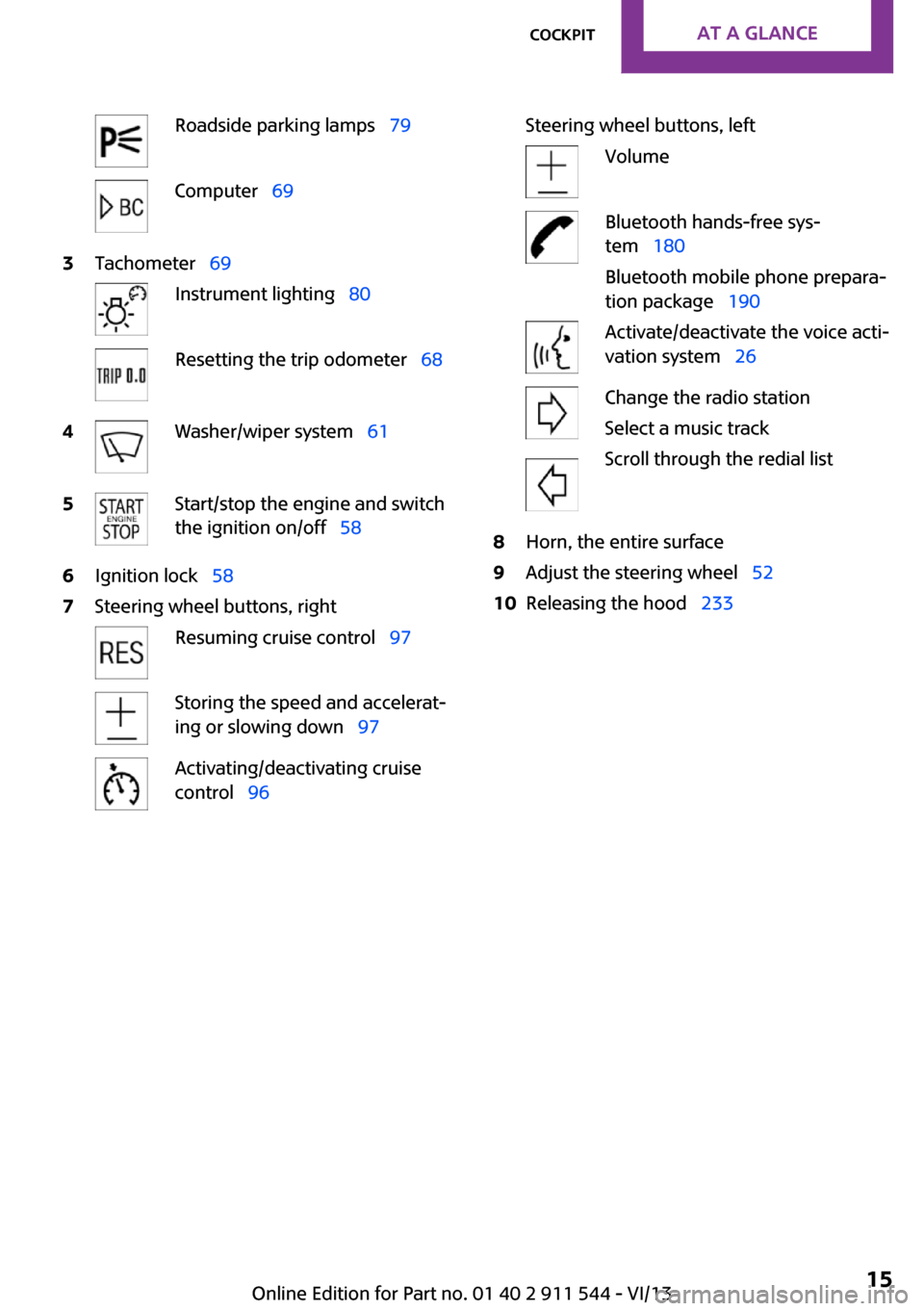
Roadside parking lamps 79Computer 693Tachometer 69Instrument lighting 80Resetting the trip odometer 684Washer/wiper system 615Start/stop the engine and switch
the ignition on/off 586Ignition lock 587Steering wheel buttons, rightResuming cruise control 97Storing the speed and accelerat‐
ing or slowing down 97Activating/deactivating cruise
control 96Steering wheel buttons, leftVolumeBluetooth hands-free sys‐
tem 180
Bluetooth mobile phone prepara‐
tion package 190Activate/deactivate the voice acti‐
vation system 26Change the radio station
Select a music track
Scroll through the redial list8Horn, the entire surface9Adjust the steering wheel 5210Releasing the hood 233Seite 15CockpitAt a glance15
Online Edition for Part no. 01 40 2 911 544 - VI/13
Page 26 of 282
Voice activation systemVehicle equipment
This chapter describes all series equipment as
well as country-specific and special equipment
offered for this model series.Therefore, it also
describes equipment that may not be found in
your vehicle, for instance due to the selected
special equipment or the country version. This
also applies to safety-related functions and sys‐
tems.
The concept▷Most functions that are displayed on the
Control Display can be operated with the
voice activation system using spoken com‐
mands. The system prompts you to make
your entries.▷Functions that can only be used when the
vehicle is stationary cannot be operated us‐
ing the voice activation system.▷The system uses a special microphone in
the headliner on the driver's side.▷›...‹ Verbal instructions in the Owner's
Manual to use with the voice activation sys‐
tem.
Requirements
Via the Control Display, set a language that is
also supported by the voice activation system
so that the spoken commands can be identi‐
fied.
Set the language, refer to page 73.
Using voice activation
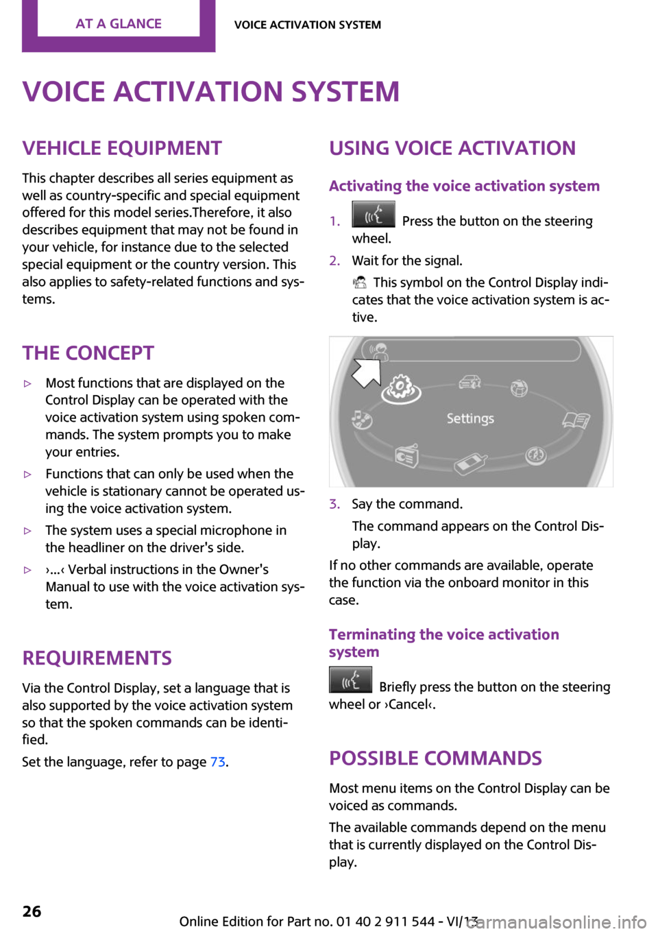
Activating the voice activation system1. Press the button on the steering
wheel.2.Wait for the signal.
This symbol on the Control Display indi‐
cates that the voice activation system is ac‐
tive.
3.Say the command.
The command appears on the Control Dis‐
play.
If no other commands are available, operate
the function via the onboard monitor in this
case.
Terminating the voice activation
system
Briefly press the button on the steering
wheel or ›Cancel‹.
Possible commands
Most menu items on the Control Display can be
voiced as commands.
The available commands depend on the menu
that is currently displayed on the Control Dis‐
play.
Seite 26At a glanceVoice activation system26
Online Edition for Part no. 01 40 2 911 544 - VI/13
Page 27 of 282
The functions of the main menu have short
commands.
Some list items, such as the phone book en‐
tries, can also be selected via the voice activa‐
tion system. Say the list items exactly as they
are displayed on the list.
Having possible commands read aloud
You can have the system read possible com‐
mands aloud: ›Voice commands‹.
For example, if the "CD" menu is displayed, the
commands for the operating the CD player are
read out loud.
Executing functions using short
commands
Functions on the main menu can be performeddirectly by means of short commands, usually
irrespective of which menu item is currently se‐
lected, for instance ›Vehicle status‹.
List of short commands of the voice activation
system, refer to page 264.
Help dialog for the voice activation
system
Calling up help dialog: ›Help‹
Additional commands for the help dialog:▷›Help with examples‹: information about the current operating options and the most
important commands for them are an‐
nounced.▷›Help with voice activation‹: information
about the principle of operation for the
voice activation system is announced.Example: playing back a
CD
Via the main menu
The commands of the menu items are spoken
out loud, in the same way as they are selected
via the MINI joystick.1.Switch on the Entertainment sound output
if necessary.2. Press the button on the steering
wheel.3.›C D and multimedia‹
The medium last played is played back.4.›C D‹5.›C D drive‹
The CD is played back.6. Press the button on the steering
wheel again to select a specific track.7.›Track ...‹ e.g., CD track 4.
Via short commands
Playback of the CD can also be started using a
short command.
1.Switch on the Entertainment sound output
if necessary.2. Press the button on the steering
wheel.3.›C D drive Track ...‹ e.g., CD track 4.
Setting the voice dialog
You can set whether the system should use the
standard dialog or a shorter version.
In the shorter variant of the voice dialog, the
announcements from the system are issued in
an abbreviated form.
Seite 27Voice activation systemAt a glance27
Online Edition for Part no. 01 40 2 911 544 - VI/13
Page 52 of 282

Interior rearview mirror
To reduce the blinding effect from the rear
when driving at night: turn the knob.
Interior rearview and exterior mirrors,
automatic dimming feature
Two photocells are used for control:
▷In the mirror frame, see arrow.▷On the back of the mirror.
For proper operation:
▷Keep the photocells clean.▷Do not cover the area between the inside
rearview mirror and the windshield.▷Do not apply stickers to the windshield in
front of the mirror.Steering wheel
Adjusting Do not adjust while driving
Do not adjust the steering wheel while
driving; otherwise, an unexpected movement
could result in an accident. ◀1.Fold the lever down.2.Move the steering wheel to the preferred
height and angle to suit your seating posi‐
tion.3.Fold the lever back.
Do not use force to swing the lever back.
Do not use force to swing the lever back
up; otherwise, the mechanism will be dam‐
aged. ◀
Seite 52ControlsAdjusting52
Online Edition for Part no. 01 40 2 911 544 - VI/13
Page 60 of 282
Engine stop
General information Take the remote control with you
Take the remote control with you when
leaving the vehicle so that children, for exam‐
ple, cannot operate the windows and injure
themselves. ◀
Set the handbrake and further secure the
vehicle as required
Set the handbrake firmly when parking; other‐
wise, the vehicle may roll. On steep upward
and downward inclines, further secure the ve‐
hicle, for example, by turning the steering
wheel in the direction of the curb. ◀
Before driving into a car wash
To make it possible for the vehicle to roll in an
automatic car wash, follow the information on
Washing in automatic car washes, refer to
page 254.
Switching off the engine
Manual transmission1.With the vehicle at a standstill, press the
Start/Stop button.2.Shift into first gear or reverse.3.Set the handbrake firmly.4.Remove the remote control from the igni‐
tion lock.
Automatic transmission
1.Engage transmission position P with the ve‐
hicle stopped.2.Press the Start/Stop button.3.Set the handbrake firmly.4.Remove the remote control from the igni‐
tion lock.Handbrake
The concept
The handbrake is primarily intended to prevent
the vehicle from rolling while parked; it brakes
the rear wheels.
Also follow the instructions under Switching off
the engine, refer to page 60.
Setting
The lever engages automatically.
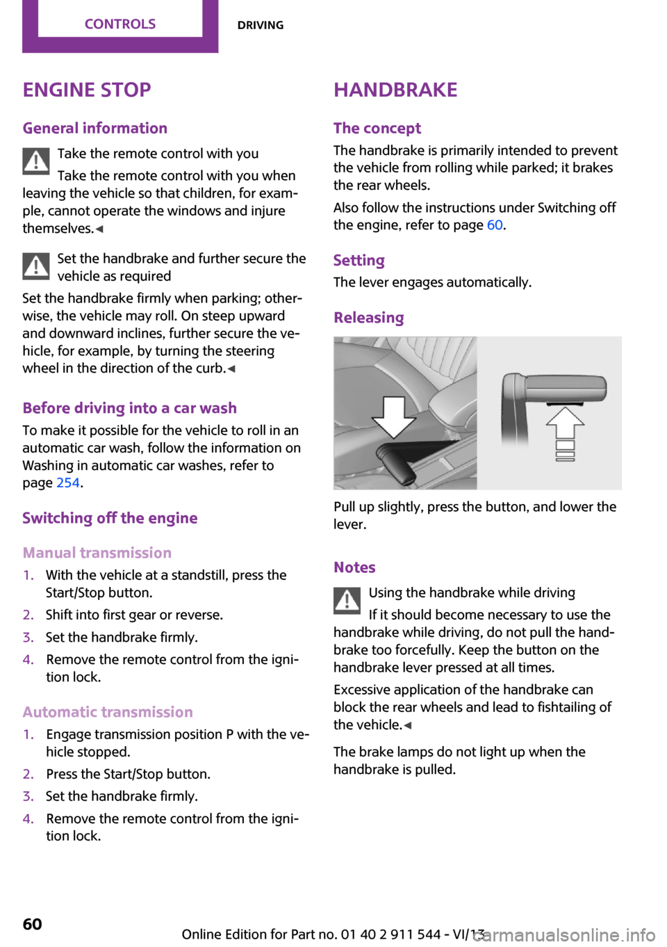
Releasing
Pull up slightly, press the button, and lower the
lever.
Notes Using the handbrake while driving
If it should become necessary to use the
handbrake while driving, do not pull the hand‐
brake too forcefully. Keep the button on the
handbrake lever pressed at all times.
Excessive application of the handbrake can
block the rear wheels and lead to fishtailing of
the vehicle. ◀
The brake lamps do not light up when the
handbrake is pulled.
Seite 60ControlsDriving60
Online Edition for Part no. 01 40 2 911 544 - VI/13
Page 66 of 282
Under normal operating conditions, fuel con‐
sumption is lowest when you are driving in po‐
sition D.
Kickdown
Kickdown is used to achieve maximum driving
performance. Press on the accelerator beyond
the resistance point at the full throttle position.
Sport program and manual mode M/S
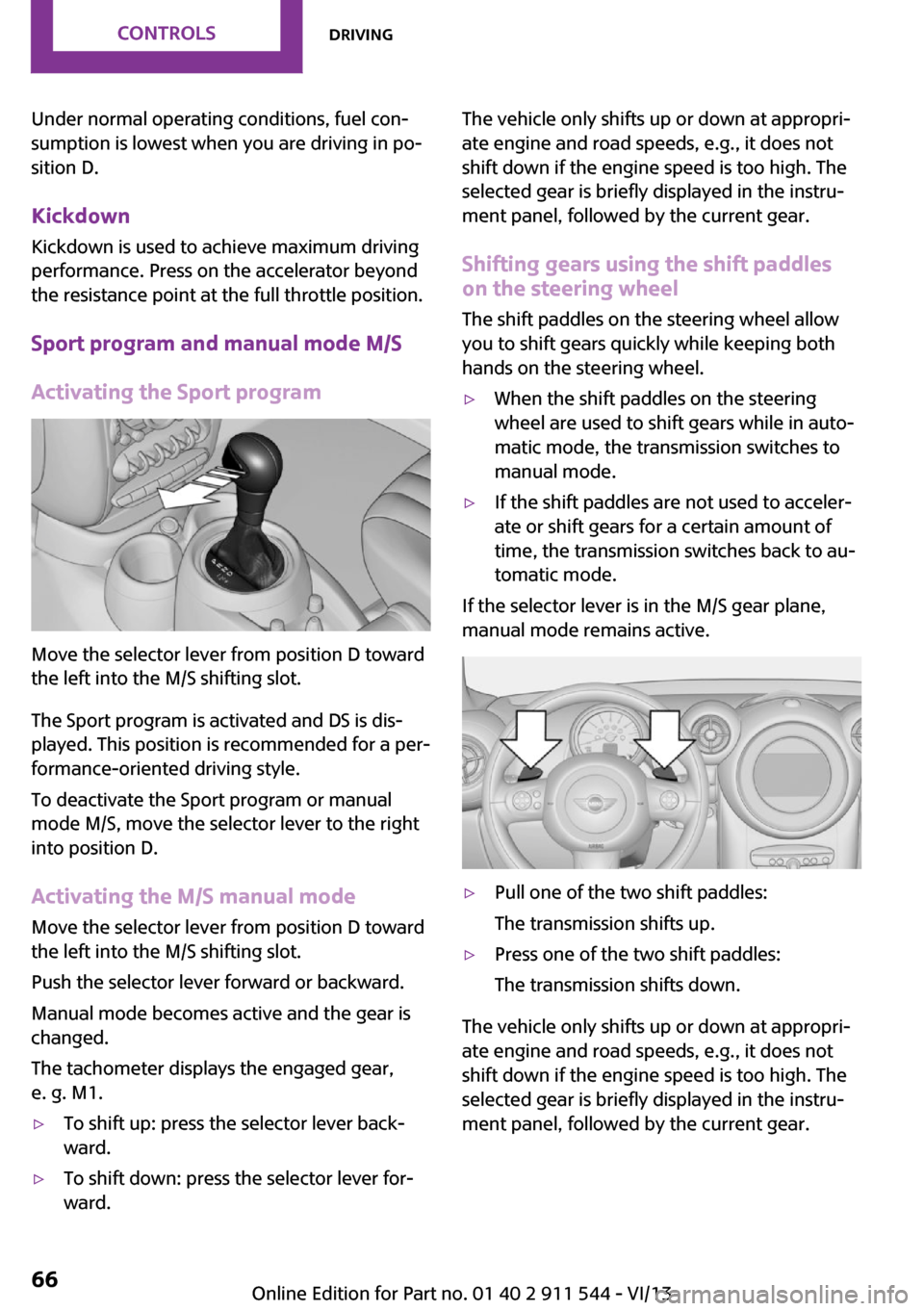
Activating the Sport program
Move the selector lever from position D toward
the left into the M/S shifting slot.
The Sport program is activated and DS is dis‐
played. This position is recommended for a per‐
formance-oriented driving style.
To deactivate the Sport program or manual
mode M/S, move the selector lever to the right
into position D.
Activating the M/S manual mode Move the selector lever from position D towardthe left into the M/S shifting slot.
Push the selector lever forward or backward.
Manual mode becomes active and the gear is
changed.
The tachometer displays the engaged gear,
e. g. M1.
▷To shift up: press the selector lever back‐
ward.▷To shift down: press the selector lever for‐
ward.The vehicle only shifts up or down at appropri‐
ate engine and road speeds, e.g., it does not
shift down if the engine speed is too high. The
selected gear is briefly displayed in the instru‐
ment panel, followed by the current gear.
Shifting gears using the shift paddleson the steering wheel
The shift paddles on the steering wheel allow
you to shift gears quickly while keeping both hands on the steering wheel.▷When the shift paddles on the steering
wheel are used to shift gears while in auto‐
matic mode, the transmission switches to
manual mode.▷If the shift paddles are not used to acceler‐
ate or shift gears for a certain amount of
time, the transmission switches back to au‐
tomatic mode.
If the selector lever is in the M/S gear plane,
manual mode remains active.
▷Pull one of the two shift paddles:
The transmission shifts up.▷Press one of the two shift paddles:
The transmission shifts down.
The vehicle only shifts up or down at appropri‐
ate engine and road speeds, e.g., it does not
shift down if the engine speed is too high. The
selected gear is briefly displayed in the instru‐
ment panel, followed by the current gear.
Seite 66ControlsDriving66
Online Edition for Part no. 01 40 2 911 544 - VI/13
Page 80 of 282
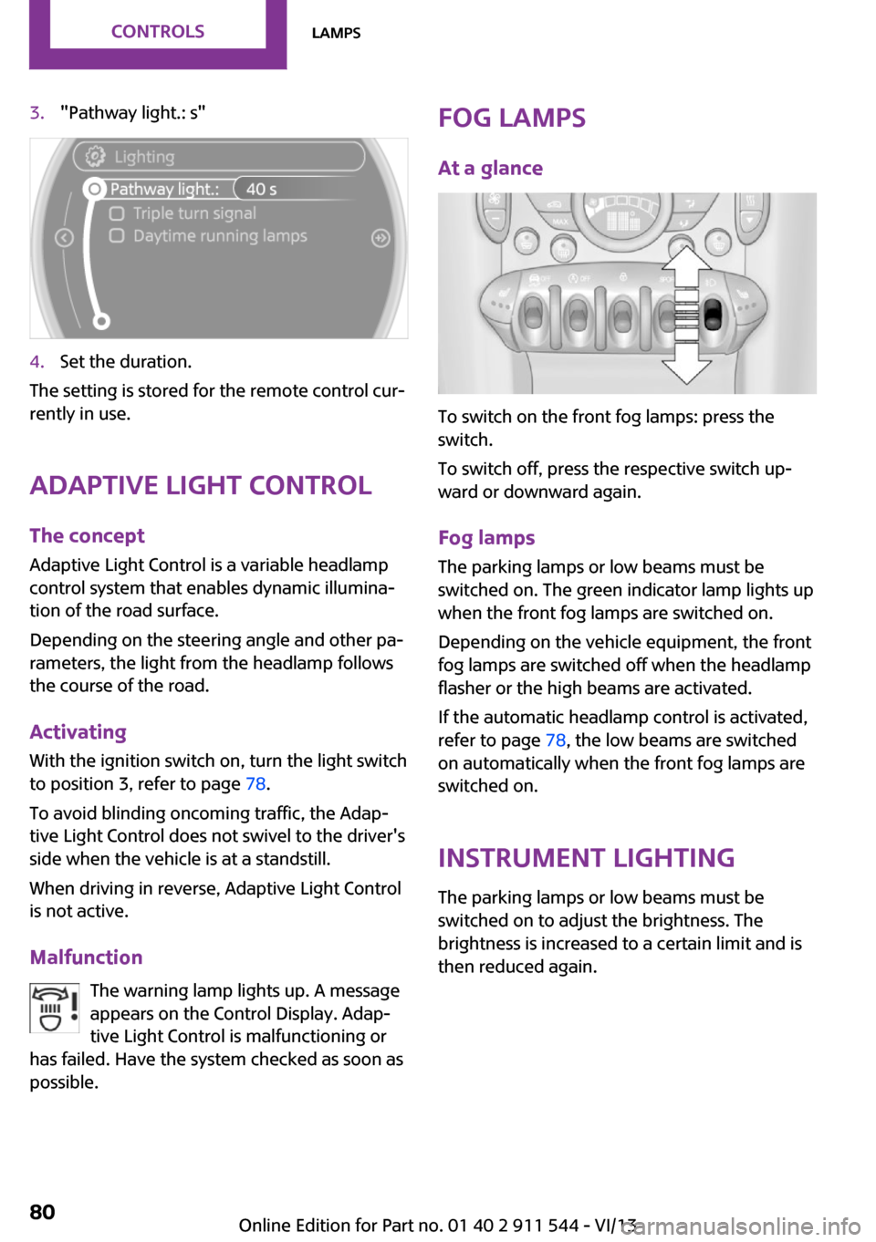
3."Pathway light.: s"4.Set the duration.
The setting is stored for the remote control cur‐
rently in use.
Adaptive Light Control
The concept
Adaptive Light Control is a variable headlamp
control system that enables dynamic illumina‐
tion of the road surface.
Depending on the steering angle and other pa‐
rameters, the light from the headlamp follows
the course of the road.
Activating
With the ignition switch on, turn the light switch
to position 3, refer to page 78.
To avoid blinding oncoming traffic, the Adap‐
tive Light Control does not swivel to the driver's
side when the vehicle is at a standstill.
When driving in reverse, Adaptive Light Control
is not active.
Malfunction The warning lamp lights up. A message
appears on the Control Display. Adap‐
tive Light Control is malfunctioning or
has failed. Have the system checked as soon as
possible.
Fog lamps
At a glance
To switch on the front fog lamps: press the
switch.
To switch off, press the respective switch up‐
ward or downward again.
Fog lamps
The parking lamps or low beams must be
switched on. The green indicator lamp lights up
when the front fog lamps are switched on.
Depending on the vehicle equipment, the front
fog lamps are switched off when the headlamp
flasher or the high beams are activated.
If the automatic headlamp control is activated,
refer to page 78, the low beams are switched
on automatically when the front fog lamps are
switched on.
Instrument lightingThe parking lamps or low beams must be
switched on to adjust the brightness. The
brightness is increased to a certain limit and is
then reduced again.
Seite 80ControlsLamps80
Online Edition for Part no. 01 40 2 911 544 - VI/13
Page 83 of 282
Protective action
Airbags are not triggered in every impact situa‐
tion, e.g., in less severe accidents or rear-end
collisions.
Information on how to ensure the opti‐
mal protective effect of the airbags▷Keep at a distance from the airbags.▷Always grasp the steering wheel on the
steering wheel rim, holding your hands at
the 3 o'clock and 9 o'clock positions, to
keep the danger of injury to your hands or
arms as low as possible if the airbag is trig‐
gered.▷There should be no people, animals, or ob‐
jects between an airbag and a person.▷Do not use the cover of the front airbag on
the front passenger side as a storage area.▷Keep the dashboard and window on the
front passenger side clear, i.e., do not cover
with adhesive labels or coverings, and do
not attach holders such as for navigation in‐
struments and mobile phones.▷Make sure that the front passenger is sitting
correctly, i.e., keeps his or her feet and legs
in the footwell; otherwise, leg injuries can
occur if the front airbag is triggered.▷Do not place slip covers, seat cushions or
other objects on the front passenger seat
that are not approved specifically for seats
with integrated side airbags.▷Do not hang pieces of clothing, such as
jackets, over the backrests.▷Make sure that occupants keep their heads
away from the side airbag and do not rest
against the head airbag; otherwise, injuries
can occur if the airbags are triggered.▷Do not remove the airbag restraint system.▷Do not remove the steering wheel.▷Do not apply adhesive materials to the air‐
bag cover panels, cover them or modify
them in any way.▷Never modify either the individual compo‐
nents or the wiring in the airbag system.
This also applies to steering wheel covers,
the dashboard, the seats, the roof pillars
and the sides of the headliner. ◀
Even when all instructions are followed closely,
injury from contact with the airbags cannot be
ruled out in certain situations.
The ignition and inflation noise may lead to
short-term and, in most cases, temporary hear‐
ing impairment in sensitive individuals.
In the case of a malfunction, deactivation
and after triggering of the airbags
Do not touch the individual components imme‐
diately after the system has been triggered;
otherwise, there is the danger of burns.
Only have the airbags checked, repaired or dis‐
mantled and the airbag generator scrapped by
your service center or a workshop that has the
necessary authorization for handling explo‐
sives.
Non-professional attempts to service the sys‐
tem could lead to failure in an emergency or
undesired triggering of the airbag, either of
which could result in injury. ◀
Warning notices and information about the air‐
bags can also be found on the sun visors.
Automatic deactivation of the front
passenger airbags
The system determines whether the front pas‐
senger seat is occupied by measuring the elec‐
trical resistance of the human body.
The front, side, and knee airbags on the front
passenger side are activated or deactivated ac‐
cordingly by the system.
The indicator lamp above the interior rearview
mirror, refer to page 84, shows the current
status of the front passenger airbags, deacti‐
vated or activated.
Seite 83SafetyControls83
Online Edition for Part no. 01 40 2 911 544 - VI/13
Page 86 of 282
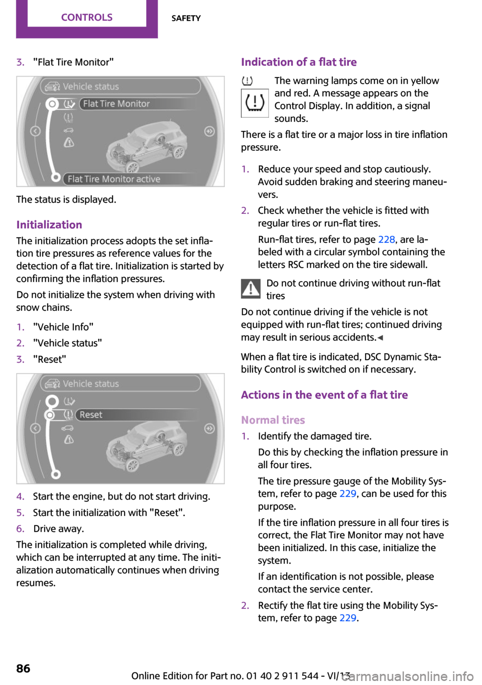
3."Flat Tire Monitor"
The status is displayed.
Initialization The initialization process adopts the set infla‐
tion tire pressures as reference values for the
detection of a flat tire. Initialization is started by
confirming the inflation pressures.
Do not initialize the system when driving with
snow chains.
1."Vehicle Info"2."Vehicle status"3."Reset"4.Start the engine, but do not start driving.5.Start the initialization with "Reset".6.Drive away.
The initialization is completed while driving,
which can be interrupted at any time. The initi‐
alization automatically continues when driving
resumes.
Indication of a flat tire
The warning lamps come on in yellow
and red. A message appears on the
Control Display. In addition, a signal
sounds.
There is a flat tire or a major loss in tire inflation
pressure.1.Reduce your speed and stop cautiously.
Avoid sudden braking and steering maneu‐
vers.2.Check whether the vehicle is fitted with
regular tires or run-flat tires.
Run-flat tires, refer to page 228, are la‐
beled with a circular symbol containing the
letters RSC marked on the tire sidewall.
Do not continue driving without run-flat
tires
Do not continue driving if the vehicle is not
equipped with run-flat tires; continued driving
may result in serious accidents. ◀
When a flat tire is indicated, DSC Dynamic Sta‐
bility Control is switched on if necessary.
Actions in the event of a flat tire
Normal tires
1.Identify the damaged tire.
Do this by checking the inflation pressure in
all four tires.
The tire pressure gauge of the Mobility Sys‐
tem, refer to page 229, can be used for this
purpose.
If the tire inflation pressure in all four tires is
correct, the Flat Tire Monitor may not have
been initialized. In this case, initialize the
system.
If an identification is not possible, please
contact the service center.2.Rectify the flat tire using the Mobility Sys‐
tem, refer to page 229.Seite 86ControlsSafety86
Online Edition for Part no. 01 40 2 911 544 - VI/13