ESP MINI Paceman 2014 Owner's Guide
[x] Cancel search | Manufacturer: MINI, Model Year: 2014, Model line: Paceman, Model: MINI Paceman 2014Pages: 218, PDF Size: 5.5 MB
Page 83 of 218
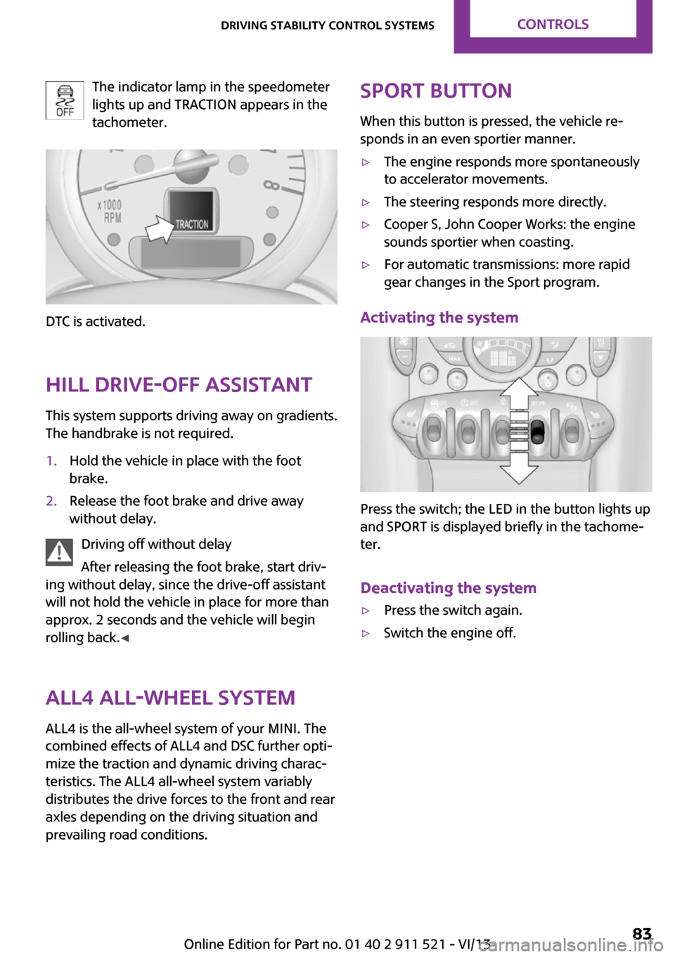
The indicator lamp in the speedometer
lights up and TRACTION appears in the
tachometer.
DTC is activated.
Hill drive-off assistant This system supports driving away on gradients.
The handbrake is not required.
1.Hold the vehicle in place with the foot
brake.2.Release the foot brake and drive away
without delay.
Driving off without delay
After releasing the foot brake, start driv‐
ing without delay, since the drive-off assistant
will not hold the vehicle in place for more than
approx. 2 seconds and the vehicle will begin
rolling back. ◀
ALL4 all-wheel system
ALL4 is the all-wheel system of your MINI. The
combined effects of ALL4 and DSC further opti‐
mize the traction and dynamic driving charac‐
teristics. The ALL4 all-wheel system variably
distributes the drive forces to the front and rear
axles depending on the driving situation and
prevailing road conditions.
Sport button
When this button is pressed, the vehicle re‐
sponds in an even sportier manner.▷The engine responds more spontaneously
to accelerator movements.▷The steering responds more directly.▷Cooper S, John Cooper Works: the engine
sounds sportier when coasting.▷For automatic transmissions: more rapid
gear changes in the Sport program.
Activating the system
Press the switch; the LED in the button lights up
and SPORT is displayed briefly in the tachome‐
ter.
Deactivating the system
▷Press the switch again.▷Switch the engine off.Seite 83Driving stability control systemsControls83
Online Edition for Part no. 01 40 2 911 521 - VI/13
Page 84 of 218

Driving comfortVehicle equipment
This chapter describes all series equipment as
well as country-specific and special equipment
offered for this model series.Therefore, it also
describes equipment that may not be found in
your vehicle, for instance due to the selected
special equipment or the country version. This
also applies to safety-related functions and sys‐
tems.
Cruise control The concept
The system is functional at speeds beginning at
approx. 20 mph/30 km/h.
The vehicle stores and maintains the speed
specified using the controls on the steering
wheel.
Do not use cruise control
Do not use the system if unfavorable con‐
ditions make it impossible to drive at a constant
speed, for instance:▷On curvy roads.▷In heavy traffic.▷On slippery roads, in fog, snow or rain, or
on a loose road surface.
Otherwise, you could lose control of the vehicle
and cause an accident. ◀
Controls
At a glance1Maintaining, storing, and increasing the
speed2Activating/deactivating cruise control3Maintaining, storing, and reducing the
speed4Resuming cruise control
Switching on
Press button 2.
The indicator lamp lights up in thespeedometer. Cruise control is ready to
operate and can be activated.
Switching off Press button 2.
▷When activated: press twice.▷When interrupted: press once.
The displays go out. The stored target speed is
cleared.
Interrupting Press button 2.
The system is interrupted automatically if
▷The brakes are applied.▷The clutch pedal is depressed.Seite 84ControlsDriving comfort84
Online Edition for Part no. 01 40 2 911 521 - VI/13
Page 93 of 218
3.Hold the hand-held transmitter of the sys‐
tem to be operated a distance of approx. 1
to 3 in/2.5 to 8 cm away from the buttons
on the interior rearview mirror. The re‐
quired distance depends on the particular
hand-held transmitter.4.Press the button of the desired function on
the hand-held transmitter and the button
being programmed on the interior rearview
mirror simultaneously and hold. The LED on
the interior rearview mirror flashes slowly at
first.5.When the LED flashes more rapidly, release
both buttons. Rapid flashing indicates that
the button on the interior rearview mirror
has been programmed.
If the LED does not flash faster after 60 sec‐
onds, change the distance between the in‐
terior rearview mirror and the hand-held
transmitter and repeat the step. Multiple
trials at different distances may be neces‐
sary. Wait at least 15 seconds between tri‐
als.6.To program additional functions on other
buttons, repeat steps 3 to 5.
The systems can be operated with the buttons
on the interior rearview mirror.
Special characteristics of alternating-
code radio systems
If the system cannot be operated after re‐
peated programming, check whether the sys‐
tem to be operated uses an alternating-code
system.
Read the operating instructions of the system
or press and hold the programmed button on
the interior rearview mirror. If the LED on the
interior rearview mirror flashes rapidly at first
and then lights up continuously for 2 seconds,
the system is equipped with an alternating-
code system. This flashing LED pattern repeats
itself for approx. 20 seconds.
In systems with an alternating-code system, the
universal garage door opener and the system
must be additionally synchronized.
Please obtain additional information on syn‐
chronization in the operating instructions of the
system being set up.
The systems will be easier to synchronize with
the aid of a second person.
Synchronization:1.Park the vehicle within range of the re‐
mote-controlled system.2.Program the corresponding button on the
interior rearview mirror as described.3.Identify and press the synchronization but‐
ton on the system being set up. You have
approx. 30 seconds for the next step.4.Press and hold the button on the interior
rearview mirror for approx. 3 seconds and
then release it. Repeat this step up to three
times if necessary to complete the synchro‐
nization procedure. When synchronization
is completed, the programmed function is
executed.
Reprogramming individual buttons
1.Switch on the ignition.2.Hold the hand-held transmitter at a dis‐
tance of approx. 1 to 3 in/2.5 to 8 cm from
the memory buttons.
The required distance depends on the par‐
ticular hand-held transmitter.3.Press the memory button of the universal
garage door opener.4.If the LED flashes slowly after approx.
20 seconds, press the transmit button on
the hand-held transmitter.5.Release both buttons when the LED flashes
rapidly.
If the LED does not flash rapidly after ap‐
prox. 60 seconds, change the distance and
repeat the step.Seite 93Interior equipmentControls93
Online Edition for Part no. 01 40 2 911 521 - VI/13
Page 94 of 218
Canada: if the LED does not flash rapidly af‐
ter approx. 60 seconds, change the dis‐
tance and repeat the step. If programming
was aborted by the hand-held transmitter,
hold down the memory button and press
and release the button on the hand-held
transmitter several times for 2 seconds.
Controls
Prior to operation
Before operating a unit with the Universal
Garage Door Opener, ensure that there are no
people, animals, or objects in the range of
movement of the system; otherwise, there is a
risk of injury or damage.
Also follow the safety instructions of the hand-
held transmitter. ◀
The system, such as the garage door, can be
operated using the button on the interior rear‐
view mirror with the engine running or the igni‐
tion switched on. When you are within the re‐
ception range of the system, press and hold the
button until the function is initiated. The LED on
the interior rearview mirror lights up continu‐
ously while the radio signal is being transmit‐
ted.
Deleting stored functions
Press the right and left buttons on the interior
rearview mirror simultaneously for approx.
20 seconds until the LED flashes rapidly. All
stored functions are deleted. The functions can‐
not be deleted individually.
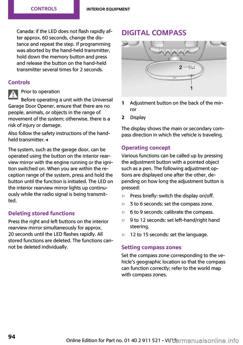
Digital compass1Adjustment button on the back of the mir‐
ror2Display
The display shows the main or secondary com‐
pass direction in which the vehicle is traveling.
Operating concept
Various functions can be called up by pressing
the adjustment button with a pointed object
such as a pen. The following adjustment op‐
tions are displayed one after the other, de‐
pending on how long the adjustment button is
pressed:
▷Press briefly: switch the display on/off.▷3 to 6 seconds: set the compass zone.▷6 to 9 seconds: calibrate the compass.▷9 to 12 seconds: set left-hand/right hand
steering.▷12 to 15 seconds: set the language.
Setting compass zones
Set the compass zone corresponding to the ve‐
hicle's geographic location so that the compass
can function correctly; refer to the world map
with compass zones.
Seite 94ControlsInterior equipment94
Online Edition for Part no. 01 40 2 911 521 - VI/13
Page 98 of 218
Cargo areaCargo cover Do not place objects on the covers
Do not place objects on the cover; if you
do so, they may pose a danger to vehicle occu‐
pants during braking or evasive maneuvers or
damage the cover. ◀
When the tailgate is opened, the cargo cover is
raised.
To load bulky luggage, the cover can be re‐
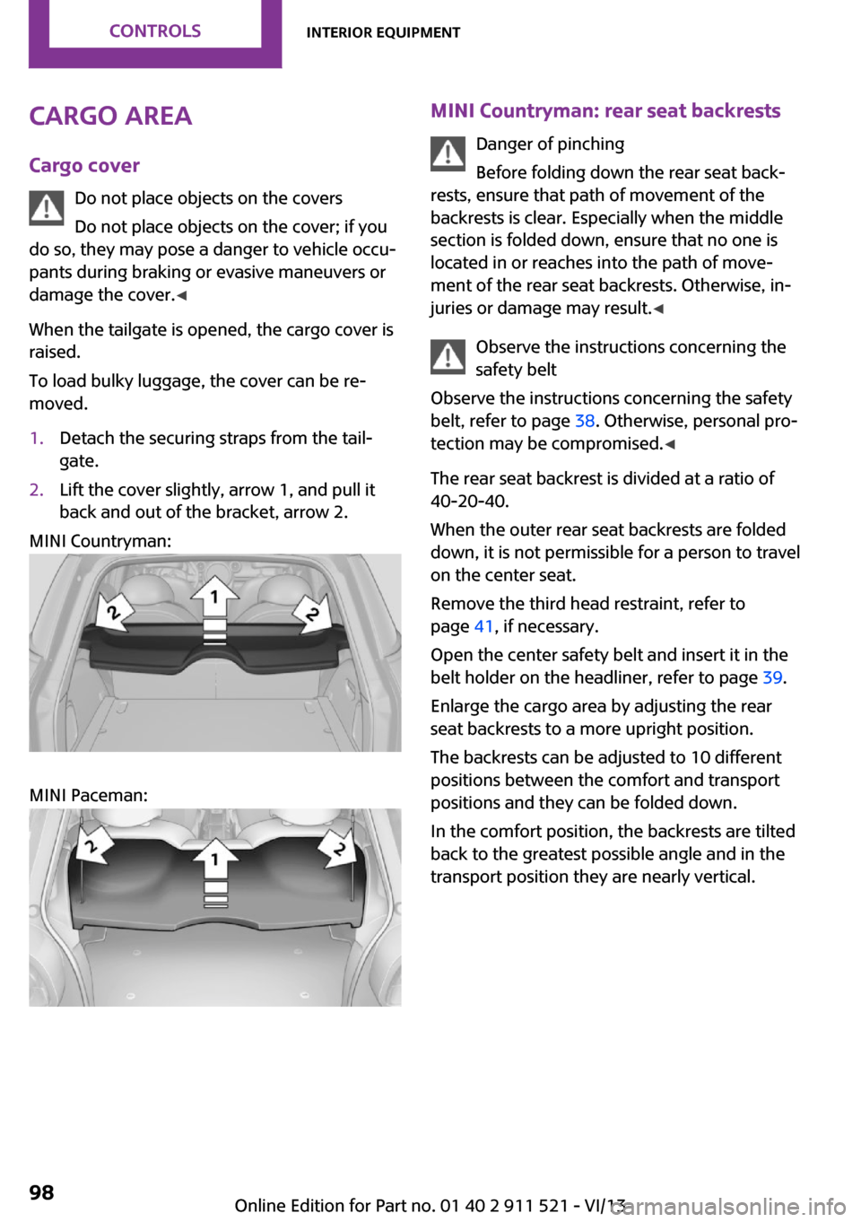
moved.1.Detach the securing straps from the tail‐
gate.2.Lift the cover slightly, arrow 1, and pull it
back and out of the bracket, arrow 2.
MINI Countryman:
MINI Paceman:
MINI Countryman: rear seat backrests
Danger of pinching
Before folding down the rear seat back‐
rests, ensure that path of movement of the
backrests is clear. Especially when the middle
section is folded down, ensure that no one is
located in or reaches into the path of move‐ ment of the rear seat backrests. Otherwise, in‐
juries or damage may result. ◀
Observe the instructions concerning the
safety belt
Observe the instructions concerning the safety
belt, refer to page 38. Otherwise, personal pro‐
tection may be compromised. ◀
The rear seat backrest is divided at a ratio of 40-20-40.
When the outer rear seat backrests are folded down, it is not permissible for a person to travel
on the center seat.
Remove the third head restraint, refer to
page 41, if necessary.
Open the center safety belt and insert it in the
belt holder on the headliner, refer to page 39.
Enlarge the cargo area by adjusting the rear
seat backrests to a more upright position.
The backrests can be adjusted to 10 different
positions between the comfort and transport
positions and they can be folded down.
In the comfort position, the backrests are tilted
back to the greatest possible angle and in the
transport position they are nearly vertical.Seite 98ControlsInterior equipment98
Online Edition for Part no. 01 40 2 911 521 - VI/13
Page 99 of 218
Before beginning with the mounting of a child
restraint fixing system, note the instructions,
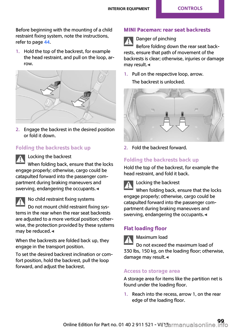
refer to page 44.1.Hold the top of the backrest, for example
the head restraint, and pull on the loop, ar‐
row.2.Engage the backrest in the desired position
or fold it down.
Folding the backrests back up
Locking the backrest
When folding back, ensure that the locks
engage properly; otherwise, cargo could be
catapulted forward into the passenger com‐
partment during braking maneuvers and
swerving, endangering the occupants. ◀
No child restraint fixing systems
Do not mount child restraint fixing sys‐
tems in the rear when the rear seat backrests
are adjusted to a more vertical position; other‐
wise, the protection provided by these systems
may be reduced. ◀
When the backrests are folded back up, they
engage in the transport position.
To set the desired backrest inclination or com‐
fort position, hold the backrest, pull the loop
forward, and adjust the backrest.
MINI Paceman: rear seat backrests
Danger of pinching
Before folding down the rear seat back‐
rests, ensure that path of movement of the
backrests is clear; otherwise, injuries or damage
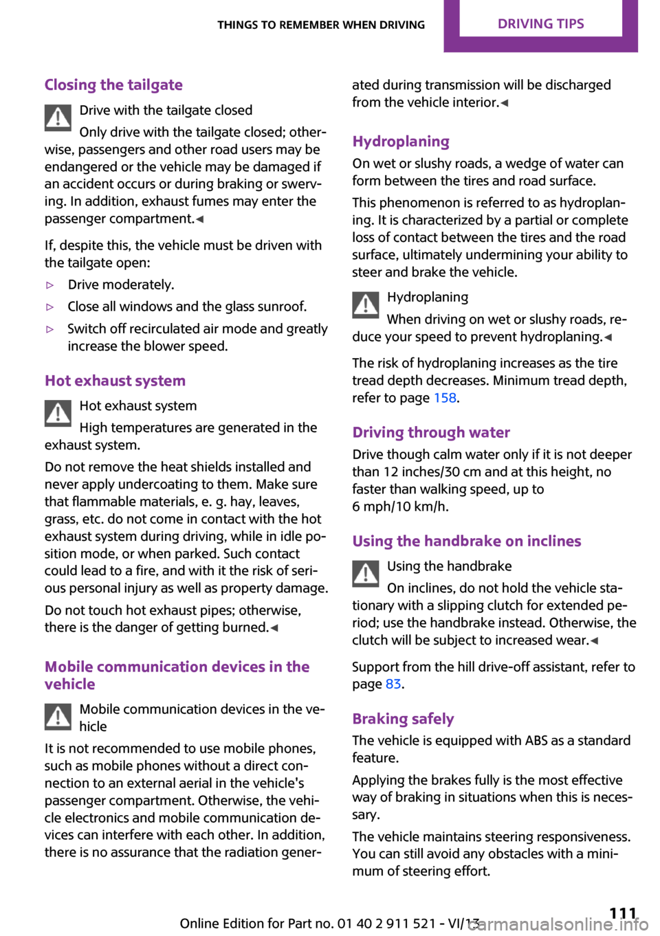
may result. ◀1.Pull on the respective loop, arrow.
The backrest is unlocked.2.Fold the backrest forward.
Folding the backrests back up Hold the top of the backrest, for example the
head restraint, and fold it back.
Locking the backrest
When folding back, ensure that the locks
engage properly; otherwise, cargo could be
catapulted forward into the passenger com‐
partment during braking maneuvers and
swerving, endangering the occupants. ◀
Flat loading floor Maximum load
Do not exceed the maximum load of
330 lbs, 150 kg, on the loading floor; otherwise,
damage may result. ◀
Access to storage area A storage area for items like the partition net is
found under the loading floor.
1.Reach into the recess, arrow 1, on the rear
edge of the loading floor.Seite 99Interior equipmentControls99
Online Edition for Part no. 01 40 2 911 521 - VI/13
Page 111 of 218
Closing the tailgateDrive with the tailgate closed
Only drive with the tailgate closed; other‐
wise, passengers and other road users may be
endangered or the vehicle may be damaged if
an accident occurs or during braking or swerv‐
ing. In addition, exhaust fumes may enter the
passenger compartment. ◀
If, despite this, the vehicle must be driven with
the tailgate open:▷Drive moderately.▷Close all windows and the glass sunroof.▷Switch off recirculated air mode and greatly
increase the blower speed.
Hot exhaust system
Hot exhaust system
High temperatures are generated in the
exhaust system.
Do not remove the heat shields installed and
never apply undercoating to them. Make sure
that flammable materials, e. g. hay, leaves,
grass, etc. do not come in contact with the hot
exhaust system during driving, while in idle po‐
sition mode, or when parked. Such contact
could lead to a fire, and with it the risk of seri‐
ous personal injury as well as property damage.
Do not touch hot exhaust pipes; otherwise,
there is the danger of getting burned. ◀
Mobile communication devices in the
vehicle
Mobile communication devices in the ve‐
hicle
It is not recommended to use mobile phones,
such as mobile phones without a direct con‐
nection to an external aerial in the vehicle's
passenger compartment. Otherwise, the vehi‐
cle electronics and mobile communication de‐
vices can interfere with each other. In addition,
there is no assurance that the radiation gener‐
ated during transmission will be discharged
from the vehicle interior. ◀
Hydroplaning On wet or slushy roads, a wedge of water can
form between the tires and road surface.
This phenomenon is referred to as hydroplan‐
ing. It is characterized by a partial or complete
loss of contact between the tires and the road
surface, ultimately undermining your ability to
steer and brake the vehicle.
Hydroplaning
When driving on wet or slushy roads, re‐
duce your speed to prevent hydroplaning. ◀
The risk of hydroplaning increases as the tire
tread depth decreases. Minimum tread depth,
refer to page 158.
Driving through water Drive though calm water only if it is not deeper
than 12 inches/30 cm and at this height, no
faster than walking speed, up to
6 mph/10 km/h.
Using the handbrake on inclines Using the handbrake
On inclines, do not hold the vehicle sta‐
tionary with a slipping clutch for extended pe‐
riod; use the handbrake instead. Otherwise, the
clutch will be subject to increased wear. ◀
Support from the hill drive-off assistant, refer to
page 83.
Braking safely The vehicle is equipped with ABS as a standard
feature.
Applying the brakes fully is the most effective
way of braking in situations when this is neces‐
sary.
The vehicle maintains steering responsiveness.
You can still avoid any obstacles with a mini‐
mum of steering effort.Seite 111Things to remember when drivingDriving tips111
Online Edition for Part no. 01 40 2 911 521 - VI/13
Page 112 of 218
Pulsation of the brake pedal and sounds from
the hydraulic circuits indicate that ABS is in its
active mode.
Do not let your foot rest on the brake
pedal
Do not drive with your foot resting on the brake
pedal. Even light but consistent pedal pressure
can lead to high temperatures, brake wear and
possibly even brake failure. ◀
Objects in the area around the pedals No objects in the area around the pedals
Keep floor mats, carpets, and any other
objects out of the area of motion of the pedals;
otherwise, the function of the pedals could be
impeded while driving
Do not place additional floor mats over existing
mats or other objects.
Only use floor mats that have been approved
for the vehicle and can be properly fixed in
place.
Ensure that the floor mats are securely fastened
again when they are returned after being re‐
moved, such as for cleaning. ◀
Driving in wet conditions
When roads are wet or there is heavy rain, briefly exert gentle pressure on the brake pedal
every few miles.
Ensure that this action does not endanger other
road users.
The heat generated in this process helps dry
the brake discs and pads.
In this way braking efficiency will be available
when you need it.
HillsDrive long or steep downhill gradients in the
gear in which the least braking is required. Oth‐
erwise, the brake system may overheat, result‐
ing in a reduction in the brake system effi‐
ciency.You can increase the engine's braking effect by
shifting down, going all the way to first gear, if
necessary.
Downshifting in manual mode of the automatic
transmission, refer to page 57.
Avoid load on the brakes
Avoid placing excessive load on the brake
system. Light but consistent brake pressure can
lead to high temperatures, brake wear and
possibly even brake failure. ◀
Do not drive in neutral
Never drive with the transmission in neu‐
tral, with the engine switched off or with the
clutch depressed; otherwise, you will have nei‐
ther the braking action of the engine or nor its
power assistance when braking or steering. ◀
Brake disc corrosion Corrosion on the brake discs and contamina‐
tion on the brake pads are furthered by:▷Low mileage.▷Extended periods when the vehicle is not
used at all.▷Infrequent use of the brakes.
Corrosion occurs when the minimum pressure
that must be exerted by the pads during brake
applications to clean the discs is not reached.
Should corrosion form on the brake discs, the
brakes will tend to respond with a pulsating ef‐
fect that generally cannot be corrected.
When the vehicle is parked
When using the automatic climate control, con‐
densation water develops that exits under‐
neath the vehicle.
Therefore, traces of condensed water under the
vehicle are normal.
After the engine is switched off, the coolant
pump may continue running for some time in
the MINI Cooper S. This causes noises in the en‐
gine compartment.
Seite 112Driving tipsThings to remember when driving112
Online Edition for Part no. 01 40 2 911 521 - VI/13
Page 116 of 218
MINI Paceman
Securing cargo
▷Secure smaller and lighter pieces with tight‐
ening belts or straps.▷Secure larger and heavier pieces with cargo
straps.
Adhere to the information included with
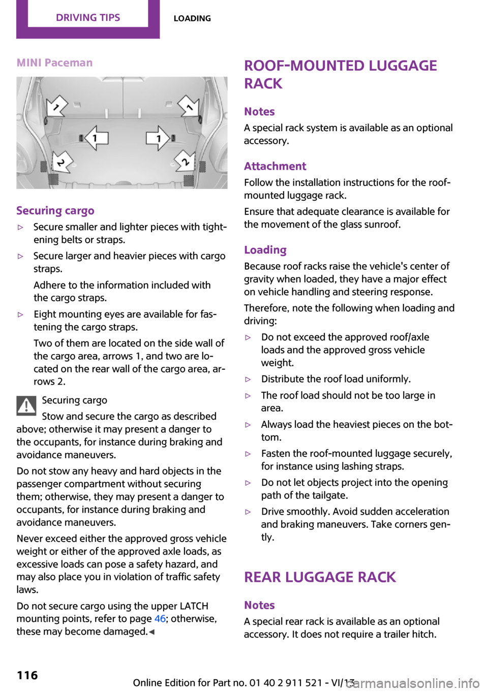
the cargo straps.▷Eight mounting eyes are available for fas‐
tening the cargo straps.
Two of them are located on the side wall of
the cargo area, arrows 1, and two are lo‐
cated on the rear wall of the cargo area, ar‐
rows 2.
Securing cargo
Stow and secure the cargo as described
above; otherwise it may present a danger to
the occupants, for instance during braking and
avoidance maneuvers.
Do not stow any heavy and hard objects in the
passenger compartment without securing
them; otherwise, they may present a danger to
occupants, for instance during braking and
avoidance maneuvers.
Never exceed either the approved gross vehicle
weight or either of the approved axle loads, as
excessive loads can pose a safety hazard, and
may also place you in violation of traffic safety
laws.
Do not secure cargo using the upper LATCH
mounting points, refer to page 46; otherwise,
these may become damaged. ◀
Roof-mounted luggage
rack
Notes
A special rack system is available as an optional
accessory.
Attachment Follow the installation instructions for the roof-mounted luggage rack.
Ensure that adequate clearance is available for
the movement of the glass sunroof.
Loading Because roof racks raise the vehicle's center of
gravity when loaded, they have a major effect
on vehicle handling and steering response.
Therefore, note the following when loading and
driving:▷Do not exceed the approved roof/axle
loads and the approved gross vehicle
weight.▷Distribute the roof load uniformly.▷The roof load should not be too large in
area.▷Always load the heaviest pieces on the bot‐
tom.▷Fasten the roof-mounted luggage securely,
for instance using lashing straps.▷Do not let objects project into the opening
path of the tailgate.▷Drive smoothly. Avoid sudden acceleration
and braking maneuvers. Take corners gen‐
tly.
Rear luggage rack
Notes A special rear rack is available as an optional
accessory. It does not require a trailer hitch.
Seite 116Driving tipsLoading116
Online Edition for Part no. 01 40 2 911 521 - VI/13
Page 117 of 218
Follow the installation instructions for the rear
rack.
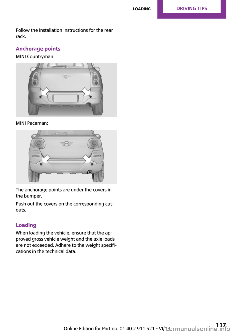
Anchorage points
MINI Countryman:
MINI Paceman:
The anchorage points are under the covers in
the bumper.
Push out the covers on the corresponding cut‐
outs.
Loading
When loading the vehicle, ensure that the ap‐
proved gross vehicle weight and the axle loads
are not exceeded. Adhere to the weight specifi‐
cations in the technical data.
Seite 117LoadingDriving tips117
Online Edition for Part no. 01 40 2 911 521 - VI/13