ECO mode MINI Paceman 2014 Owner's Manual
[x] Cancel search | Manufacturer: MINI, Model Year: 2014, Model line: Paceman, Model: MINI Paceman 2014Pages: 218, PDF Size: 5.5 MB
Page 8 of 218
your skin by washing thoroughly with soap and
water.
Service and warranty
We recommend that you read this publication
thoroughly. Your vehicle is covered by the fol‐
lowing warranties:▷New Vehicle Limited Warranty.▷Rust Perforation Limited Warranty.▷Federal Emissions System Defect Warranty.▷Federal Emissions Performance Warranty.▷California Emission Control System Limited
Warranty.
Detailed information about these warranties is
listed in the Service and Warranty Information
Booklet for US models or in the Warranty and
Service Guide Booklet for Canadian models.
Your vehicle has been specifically adapted and
designed to meet the particular operating con‐
ditions and homologation requirements in your
country and continental region in order to de‐
liver the full driving pleasure while the vehicle is
operated under those conditions. If you wish to
operate your vehicle in another country or re‐
gion, you may be required to adapt your vehi‐
cle to meet different prevailing operating con‐
ditions and homologation requirements. You
should also be aware of any applicable war‐
ranty limitations or exclusions for such country
or region. In such case, please contact Cus‐
tomer Relations for further information.
Maintenance
Maintain the vehicle regularly to sustain the
road safety, operational reliability and the New
Vehicle Limited Warranty.
Specifications for required maintenance meas‐
ures:
▷MINI Maintenance system▷Service and Warranty Information Booklet
for US models▷Warranty and Service Guide Booklet for
Canadian modelsIf the vehicle is not maintained according to
these specifications, this could result in serious
damage to the vehicle. Such damage is not
covered by the MINI New Vehicle Limited War‐
ranty.
Data memory
Numerous electronic components in your vehi‐
cle contain data memories that store technical
information on the vehicle condition, events and faults, either temporarily or permanently.This technical information generally documents
the state of a component, a module, a system
or the environment.▷Operating conditions of system compo‐
nents, such as filling levels.▷Status messages from the vehicle and its in‐
dividual components, such as wheel rpm/
speed, motion delay, transverse accelera‐
tion.▷Malfunctions and defects in important sys‐
tem components, such as lights and brakes.▷Vehicle responses to special driving situa‐
tions, such as airbag deployment, use of
the stability control systems.▷Ambient conditions, such as the tempera‐
ture.
These data are of a technical nature only and
are used to detect and eliminate faults and to
optimize vehicle functions. Travel profiles of
routes driven with the vehicle cannot be cre‐
ated from these data. If services are used, for
instance in the event of repairs, service proc‐
esses, warranty cases, quality assurance, etc.,
this technical information can be read out from
the event and fault data memories by service
personnel, including the manufacturer, using
special diagnosis tools. This service personnel
can provide you with more information if
needed. After troubleshooting, the information
in the fault memory is cleared or overwritten
continuously.
Seite 8Notes8
Online Edition for Part no. 01 40 2 911 521 - VI/13
Page 14 of 218
CockpitVehicle equipment
This chapter describes all series equipment as
well as country-specific and special equipment
offered for this model series.Therefore, it alsodescribes equipment that may not be found in
your vehicle, for instance due to the selected
special equipment or the country version. This
also applies to safety-related functions and sys‐
tems.
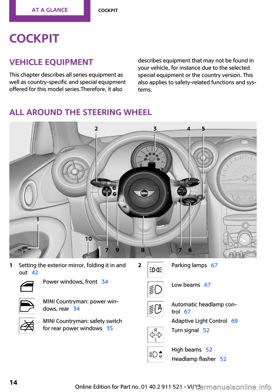
All around the steering wheel
1Setting the exterior mirror, folding it in and
out 42Power windows, front 34MINI Countryman: power win‐
dows, rear 34MINI Countryman: safety switch
for rear power windows 352Parking lamps 67Low beams 67Automatic headlamp con‐
trol 67
Adaptive Light Control 69Turn signal 52High beams 52
Headlamp flasher 52Seite 14At a glanceCockpit14
Online Edition for Part no. 01 40 2 911 521 - VI/13
Page 22 of 218
Opening and closingVehicle equipmentThis chapter describes all series equipment as
well as country-specific and special equipment
offered for this model series.Therefore, it also
describes equipment that may not be found in
your vehicle, for instance due to the selected
special equipment or the country version. This
also applies to safety-related functions and sys‐
tems.
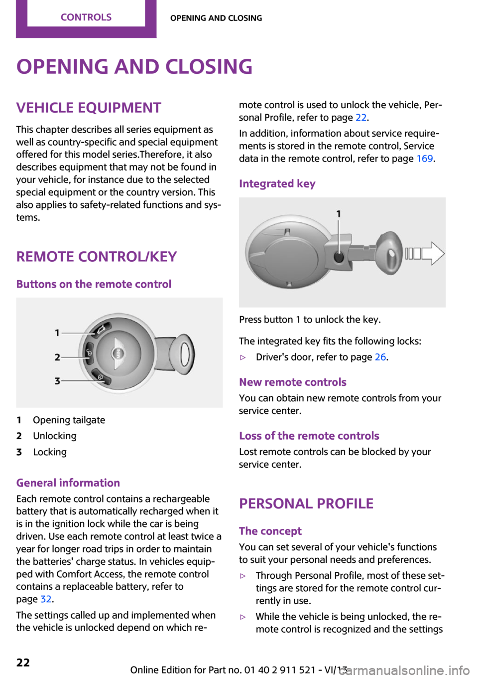
Remote control/key Buttons on the remote control1Opening tailgate2Unlocking3Locking
General information
Each remote control contains a rechargeable
battery that is automatically recharged when it
is in the ignition lock while the car is being
driven. Use each remote control at least twice a
year for longer road trips in order to maintain
the batteries' charge status. In vehicles equip‐
ped with Comfort Access, the remote control
contains a replaceable battery, refer to
page 32.
The settings called up and implemented when
the vehicle is unlocked depend on which re‐
mote control is used to unlock the vehicle, Per‐
sonal Profile, refer to page 22.
In addition, information about service require‐
ments is stored in the remote control, Service
data in the remote control, refer to page 169.
Integrated key
Press button 1 to unlock the key.
The integrated key fits the following locks:
▷Driver's door, refer to page 26.
New remote controls
You can obtain new remote controls from your
service center.
Loss of the remote controls Lost remote controls can be blocked by your
service center.
Personal Profile
The concept
You can set several of your vehicle's functions
to suit your personal needs and preferences.
▷Through Personal Profile, most of these set‐
tings are stored for the remote control cur‐
rently in use.▷While the vehicle is being unlocked, the re‐
mote control is recognized and the settingsSeite 22ControlsOpening and closing22
Online Edition for Part no. 01 40 2 911 521 - VI/13
Page 53 of 218
▷
Turn signal flashes once.▷
Triple turn signal.9.Press and hold the button until the display
changes.
The setting is stored for the remote control cur‐
rently in use.
Washer/wiper system
Notes Do not switch on the wipers if frozen
Do not switch on the wipers if they are
frozen onto the windshield; otherwise, the
wiper blades and the windshield wiper motor
may be damaged. ◀
Do not use the wipers on a dry windshield
Do not use the wipers on a dry wind‐
shield; otherwise, the wiper blades may wear
more rapidly or become damaged. ◀
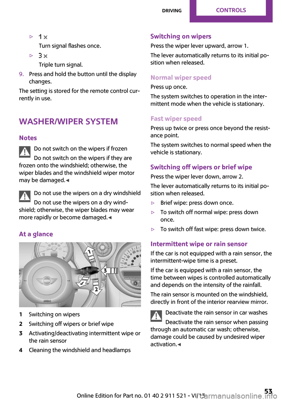
At a glance
1Switching on wipers2Switching off wipers or brief wipe3Activating/deactivating intermittent wipe or
the rain sensor4Cleaning the windshield and headlampsSwitching on wipers
Press the wiper lever upward, arrow 1.
The lever automatically returns to its initial po‐
sition when released.
Normal wiper speed
Press up once.
The system switches to operation in the inter‐
mittent mode when the vehicle is stationary.
Fast wiper speed
Press up twice or press once beyond the resist‐
ance point.
The system switches to normal speed when the
vehicle is stationary.
Switching off wipers or brief wipe Press the wiper lever down, arrow 2.
The lever automatically returns to its initial po‐
sition when released.▷Brief wipe: press down once.▷To switch off normal wipe: press down
once.▷To switch off fast wipe: press down twice.
Intermittent wipe or rain sensor
If the car is not equipped with a rain sensor, the
intermittent-wipe time is a preset.
If the car is equipped with a rain sensor, the
time between wipes is controlled automatically
and depends on the intensity of the rainfall.
The rain sensor is mounted on the windshield,
directly in front of the interior rearview mirror.
Deactivate the rain sensor in car washes
Deactivate the rain sensor when passing
through an automatic car wash; otherwise,
damage could be caused by undesired wiper
activation. ◀
Seite 53DrivingControls53
Online Edition for Part no. 01 40 2 911 521 - VI/13
Page 56 of 218
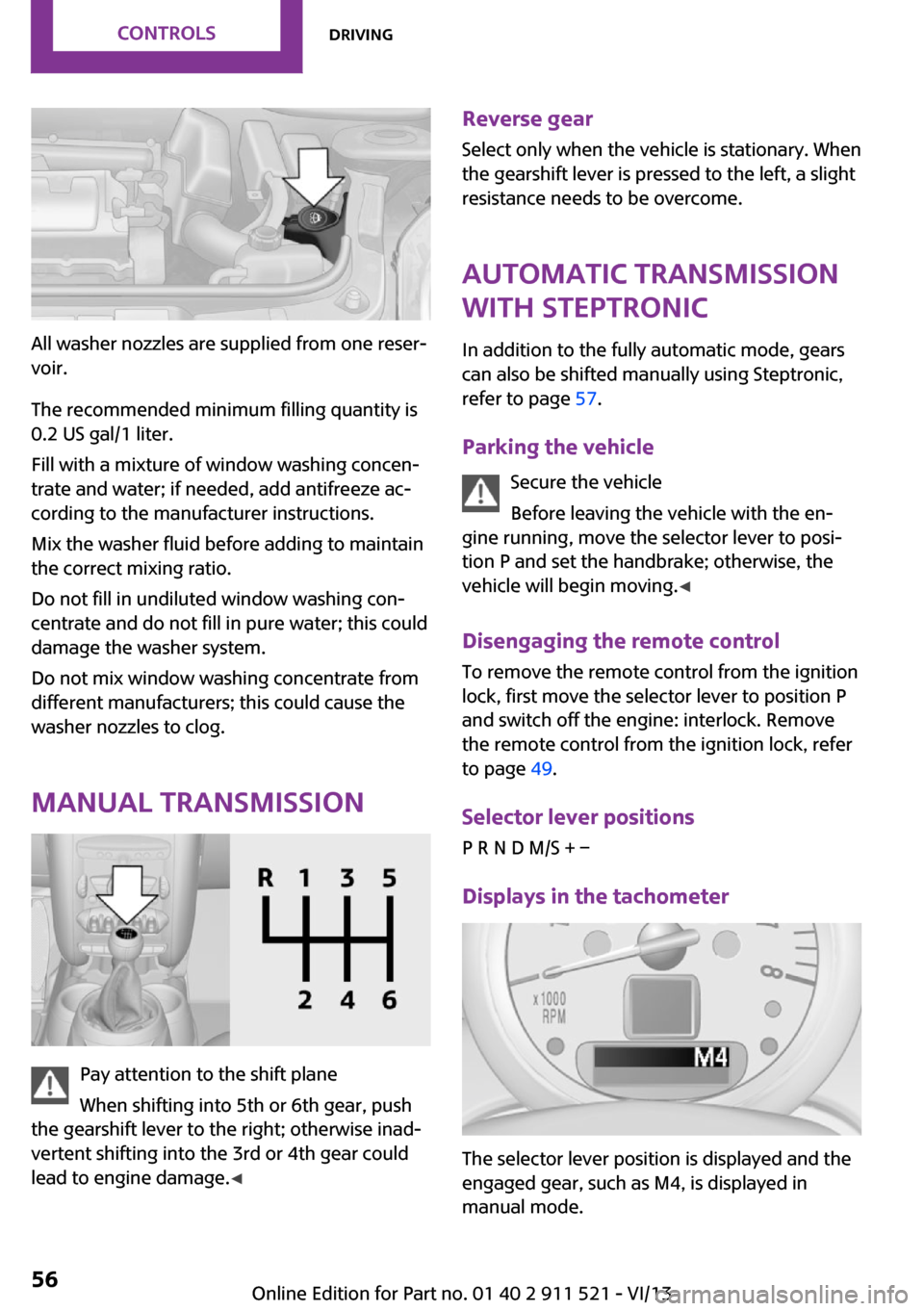
All washer nozzles are supplied from one reser‐
voir.
The recommended minimum filling quantity is
0.2 US gal/1 liter.
Fill with a mixture of window washing concen‐
trate and water; if needed, add antifreeze ac‐
cording to the manufacturer instructions.
Mix the washer fluid before adding to maintain
the correct mixing ratio.
Do not fill in undiluted window washing con‐
centrate and do not fill in pure water; this could
damage the washer system.
Do not mix window washing concentrate from
different manufacturers; this could cause the
washer nozzles to clog.
Manual transmission
Pay attention to the shift plane
When shifting into 5th or 6th gear, push
the gearshift lever to the right; otherwise inad‐
vertent shifting into the 3rd or 4th gear could
lead to engine damage. ◀
Reverse gear
Select only when the vehicle is stationary. When
the gearshift lever is pressed to the left, a slight
resistance needs to be overcome.
Automatic transmission
with Steptronic
In addition to the fully automatic mode, gears
can also be shifted manually using Steptronic,
refer to page 57.
Parking the vehicle Secure the vehicle
Before leaving the vehicle with the en‐
gine running, move the selector lever to posi‐
tion P and set the handbrake; otherwise, the
vehicle will begin moving. ◀
Disengaging the remote control
To remove the remote control from the ignition
lock, first move the selector lever to position P
and switch off the engine: interlock. Remove
the remote control from the ignition lock, refer
to page 49.
Selector lever positions
P R N D M/S + –
Displays in the tachometer
The selector lever position is displayed and the
engaged gear, such as M4, is displayed in
manual mode.
Seite 56ControlsDriving56
Online Edition for Part no. 01 40 2 911 521 - VI/13
Page 57 of 218
Changing selector lever positions▷With the ignition switched on or the engine
running, the selector lever can be moved
out of position P.▷When the vehicle is stationary, step on the
brake before shifting out of P or N; other‐
wise, the selector lever is locked: shiftlock.
Press on the brake pedal until you
start driving
To prevent the vehicle from creeping after
you select a driving position, maintain pres‐
sure on the brake pedal until you are ready
to start. ◀
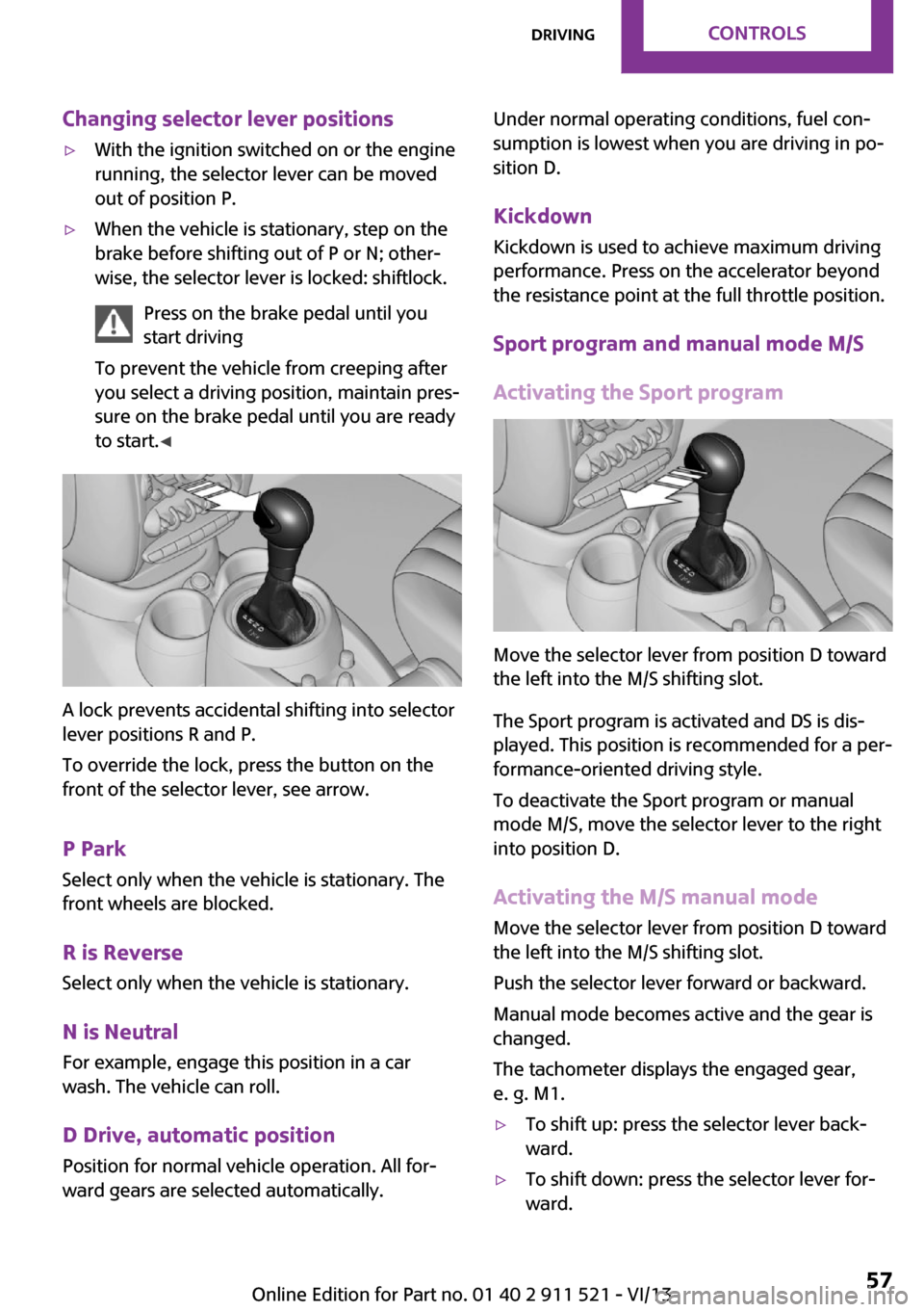
A lock prevents accidental shifting into selector
lever positions R and P.
To override the lock, press the button on the
front of the selector lever, see arrow.
P Park
Select only when the vehicle is stationary. The
front wheels are blocked.
R is Reverse
Select only when the vehicle is stationary.
N is NeutralFor example, engage this position in a car
wash. The vehicle can roll.
D Drive, automatic position Position for normal vehicle operation. All for‐
ward gears are selected automatically.
Under normal operating conditions, fuel con‐
sumption is lowest when you are driving in po‐
sition D.
Kickdown
Kickdown is used to achieve maximum driving
performance. Press on the accelerator beyond
the resistance point at the full throttle position.
Sport program and manual mode M/S
Activating the Sport program
Move the selector lever from position D toward
the left into the M/S shifting slot.
The Sport program is activated and DS is dis‐
played. This position is recommended for a per‐
formance-oriented driving style.
To deactivate the Sport program or manual
mode M/S, move the selector lever to the right
into position D.
Activating the M/S manual mode Move the selector lever from position D towardthe left into the M/S shifting slot.
Push the selector lever forward or backward.
Manual mode becomes active and the gear is
changed.
The tachometer displays the engaged gear,
e. g. M1.
▷To shift up: press the selector lever back‐
ward.▷To shift down: press the selector lever for‐
ward.Seite 57DrivingControls57
Online Edition for Part no. 01 40 2 911 521 - VI/13
Page 67 of 218
LampsVehicle equipmentThis chapter describes all series equipment as
well as country-specific and special equipment
offered for this model series.Therefore, it also
describes equipment that may not be found in
your vehicle, for instance due to the selected
special equipment or the country version. This
also applies to safety-related functions and sys‐
tems.
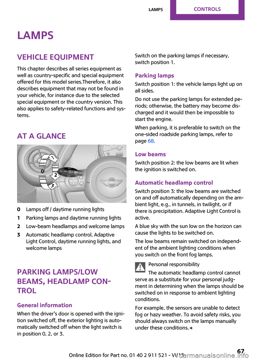
At a glance0Lamps off / daytime running lights1Parking lamps and daytime running lights2Low-beam headlamps and welcome lamps3Automatic headlamp control, Adaptive
Light Control, daytime running lights, and
welcome lamps
Parking lamps/low
beams, headlamp con‐
trol
General information
When the driver's door is opened with the igni‐
tion switched off, the exterior lighting is auto‐
matically switched off when the light switch is
in position 0, 2, or 3.
Switch on the parking lamps if necessary,
switch position 1.
Parking lamps Switch position 1: the vehicle lamps light up on
all sides.
Do not use the parking lamps for extended pe‐
riods; otherwise, the battery may become dis‐
charged and it would then be impossible to
start the engine.
When parking, it is preferable to switch on the
one-sided roadside parking lamps, refer to
page 68.
Low beams Switch position 2: the low beams are lit when
the ignition is switched on.
Automatic headlamp control Switch position 3: the low beams are switched
on and off automatically depending on the am‐
bient light, e.g., in tunnels, in twilight, or if
there is precipitation. Adaptive Light Control is
active.
A blue sky with the sun low on the horizon can
cause the lights to be switched on.
The low beams remain switched on independ‐
ent of the ambient lighting conditions when
you switch on the front fog lamps.
Personal responsibility
The automatic headlamp control cannot
serve as a substitute for your personal judg‐
ment in determining when the lamps should be
switched on in response to ambient lighting
conditions.
For example, the sensors are unable to detect
fog or hazy weather. To avoid safety risks, you
should always switch on the lamps manually
under these conditions. ◀Seite 67LampsControls67
Online Edition for Part no. 01 40 2 911 521 - VI/13
Page 81 of 218
Driving stability control systemsVehicle equipment
This chapter describes all series equipment as
well as country-specific and special equipment
offered for this model series.Therefore, it also
describes equipment that may not be found in
your vehicle, for instance due to the selected
special equipment or the country version. This
also applies to safety-related functions and sys‐
tems.
Antilock Brake System
ABS
ABS prevents locking of the wheels duringbraking.
Steerability is maintained even during full brak‐
ing. This increases active driving safety.
ABS is operational every time you start the en‐
gine.
Electronic brake-force distribution EBVThe system controls the brake pressure in the
rear wheels to ensure stable braking behavior.
CBC Cornering Brake Control
When braking in curves or during a lane
change, driving stability and steering response
are improved further.
Brake assistant When the brakes are applied rapidly, this sys‐
tem automatically produces the maximum
braking force boost. In this way, the system
helps keep the braking distance as short as
possible. This system utilizes all of the benefits
provided by ABS.Do not reduce the pressure on the brake pedal
for the duration of full braking.
Dynamic Stability Con‐
trol DSC
The concept
DSC prevents traction loss in the driving wheels
when driving away and accelerating.
DSC also recognizes unstable vehicle condi‐
tions, such as fishtailing or nose-diving. Subject
to physical limits, DSC helps to keep the vehicle
on a steady course by reducing engine speed
and by applying brakes to the individual
wheels.
DSC is operational every time you start the en‐
gine.
Adjust your driving style to the situation
An appropriate driving style is always the
responsibility of the driver.
The laws of physics cannot be repealed, even
with DSC.
Do not reduce the additional safety margin
with a risky driving style, as otherwise there is a
risk of an accident. ◀
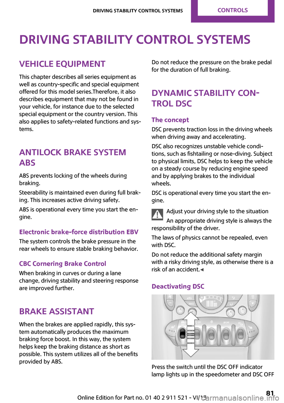
Deactivating DSC
Press the switch until the DSC OFF indicator
lamp lights up in the speedometer and DSC OFF
Seite 81Driving stability control systemsControls81
Online Edition for Part no. 01 40 2 911 521 - VI/13
Page 87 of 218
ClimateVehicle equipment
This chapter describes all series equipment as
well as country-specific and special equipment
offered for this model series.Therefore, it alsodescribes equipment that may not be found in
your vehicle, for instance due to the selected
special equipment or the country version. This
also applies to safety-related functions and sys‐
tems.
Air conditioning
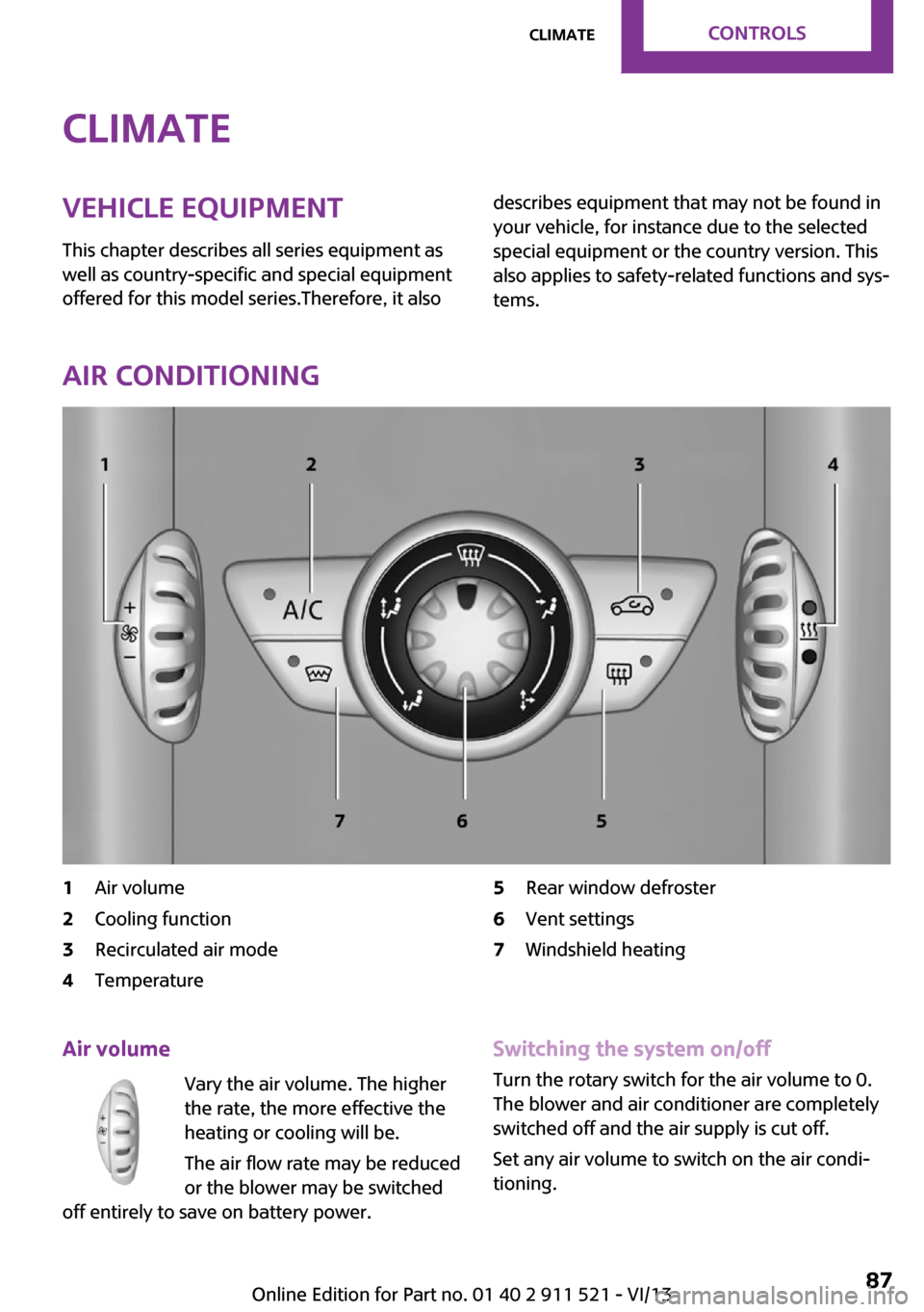
1Air volume2Cooling function3Recirculated air mode4Temperature5Rear window defroster6Vent settings7Windshield heatingAir volume
Vary the air volume. The higher
the rate, the more effective the
heating or cooling will be.
The air flow rate may be reduced
or the blower may be switched
off entirely to save on battery power.Switching the system on/off
Turn the rotary switch for the air volume to 0.
The blower and air conditioner are completely switched off and the air supply is cut off.
Set any air volume to switch on the air condi‐
tioning.Seite 87ClimateControls87
Online Edition for Part no. 01 40 2 911 521 - VI/13
Page 89 of 218
Microfilter
The microfilter traps dust and pollen. The mi‐
crofilter is changed by the service center during
routine maintenance work.
Microfilter/activated-charcoal filter
The microfilter traps dust and pollen. The acti‐
vated-charcoal filter provides additional protec‐tion by filtering gaseous pollutants from the
outside air. The service center replaces this
combined filter during routine maintenance.
Automatic climate control
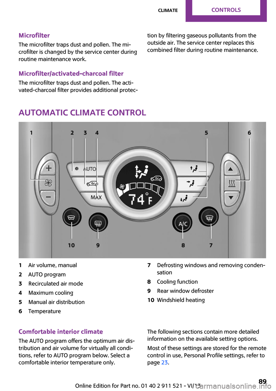
1Air volume, manual2AUTO program3Recirculated air mode4Maximum cooling5Manual air distribution6Temperature7Defrosting windows and removing conden‐
sation8Cooling function9Rear window defroster10Windshield heatingComfortable interior climate
The AUTO program offers the optimum air dis‐tribution and air volume for virtually all condi‐
tions, refer to AUTO program below. Select a
comfortable interior temperature only.The following sections contain more detailed
information on the available setting options.
Most of these settings are stored for the remote
control in use, Personal Profile settings, refer to
page 23.Seite 89ClimateControls89
Online Edition for Part no. 01 40 2 911 521 - VI/13