MINI Paceman 2015 Owner's Manual
[x] Cancel search | Manufacturer: MINI, Model Year: 2015, Model line: Paceman, Model: MINI Paceman 2015Pages: 223, PDF Size: 5.51 MB
Page 101 of 223
The lighter can be removed as soon as it pops
back out.
Danger of burns
Only hold the hot lighter by its head; oth‐
erwise, there is the danger of getting burned.
Switch off the ignition and take the remote
control with you when leaving the vehicle so
that children cannot use the lighter and burn
themselves. ◀
Connecting electrical de‐
vices
The lighter socket can be used as a socket for
electrical equipment while the engine is run‐
ning or when the ignition is switched on. The
total load of all sockets must not exceed
140 watts at 12 volt.
Avoid damaging the sockets by attempting to
insert plugs of unsuitable shape or size.
Do not connect the charger to the socket
Do not connect the battery charger to the
socket installed in the vehicle at the factory as this could damage the battery. ◀
Replace the cover after use
Replace the lighter or socket cover after
use; otherwise, objects that fall into the lighter
socket or power socket could cause a short cir‐
cuit. ◀
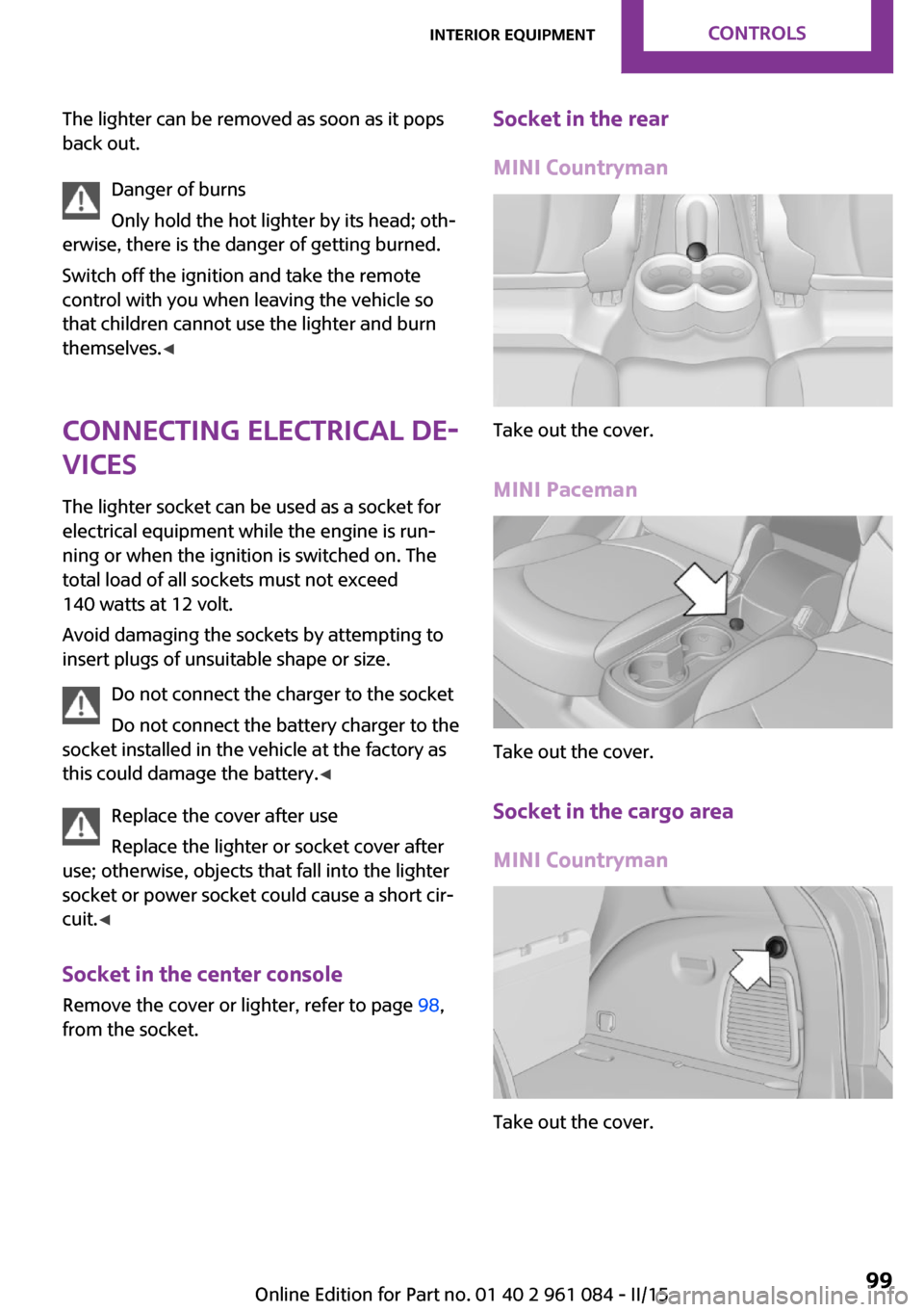
Socket in the center console
Remove the cover or lighter, refer to page 98,
from the socket.Socket in the rear
MINI Countryman
Take out the cover.
MINI Paceman
Take out the cover.
Socket in the cargo area
MINI Countryman
Take out the cover.
Seite 99Interior equipmentCONTROLS99
Online Edition for Part no. 01 40 2 961 084 - II/15
Page 102 of 223
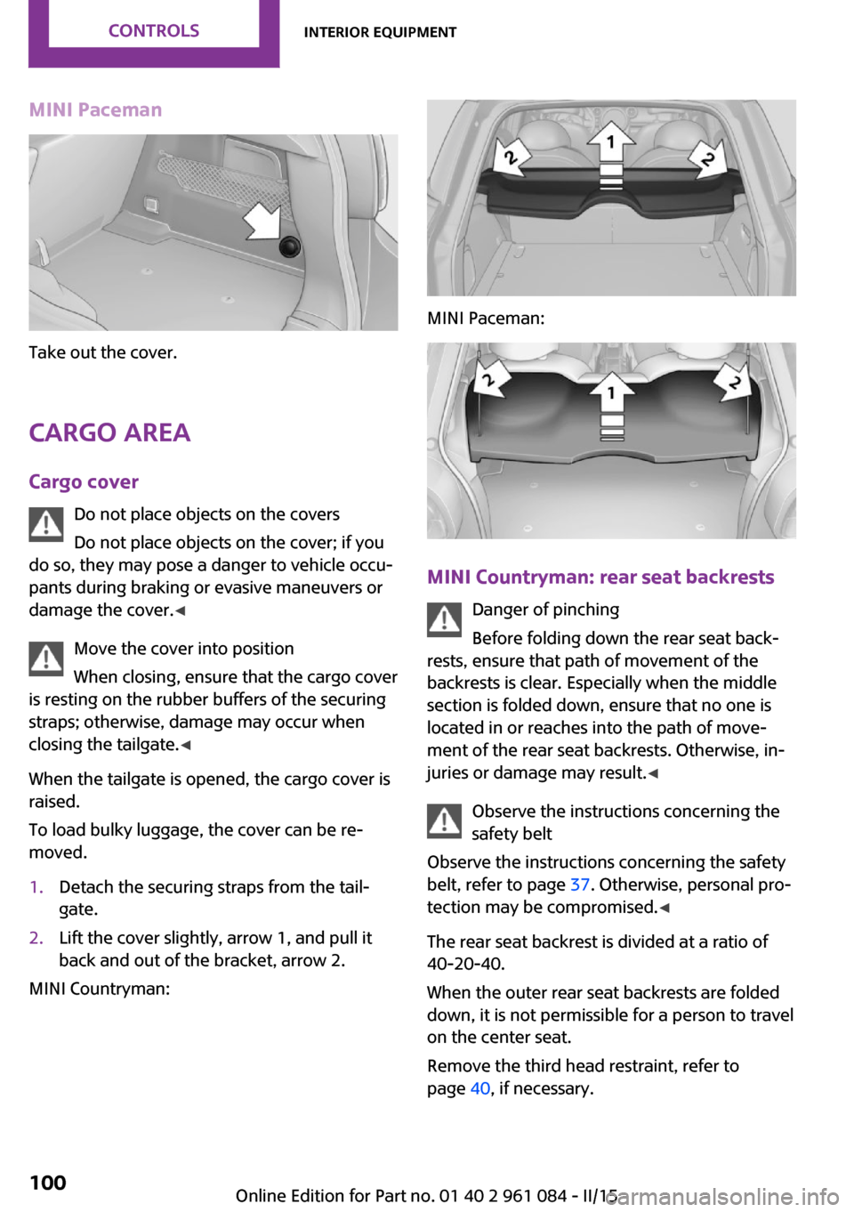
MINI Paceman
Take out the cover.
Cargo area Cargo cover Do not place objects on the covers
Do not place objects on the cover; if you
do so, they may pose a danger to vehicle occu‐
pants during braking or evasive maneuvers or
damage the cover. ◀
Move the cover into position
When closing, ensure that the cargo cover
is resting on the rubber buffers of the securing
straps; otherwise, damage may occur when
closing the tailgate. ◀
When the tailgate is opened, the cargo cover is
raised.
To load bulky luggage, the cover can be re‐
moved.
1.Detach the securing straps from the tail‐
gate.2.Lift the cover slightly, arrow 1, and pull it
back and out of the bracket, arrow 2.
MINI Countryman:
MINI Paceman:
MINI Countryman: rear seat backrests
Danger of pinching
Before folding down the rear seat back‐
rests, ensure that path of movement of the
backrests is clear. Especially when the middle
section is folded down, ensure that no one is
located in or reaches into the path of move‐ ment of the rear seat backrests. Otherwise, in‐
juries or damage may result. ◀
Observe the instructions concerning the
safety belt
Observe the instructions concerning the safety
belt, refer to page 37. Otherwise, personal pro‐
tection may be compromised. ◀
The rear seat backrest is divided at a ratio of 40-20-40.
When the outer rear seat backrests are folded down, it is not permissible for a person to travel
on the center seat.
Remove the third head restraint, refer to
page 40, if necessary.
Seite 100CONTROLSInterior equipment100
Online Edition for Part no. 01 40 2 961 084 - II/15
Page 103 of 223
Open the center safety belt and insert it in the
belt holder on the headliner, refer to page 38.
Enlarge the cargo area by adjusting the rear
seat backrests to a more upright position.
The backrests can be adjusted to 10 different
positions between the comfort and transport
positions and they can be folded down.
In the comfort position, the backrests are tilted
back to the greatest possible angle and in the
transport position they are nearly vertical.
Before beginning with the mounting of a child
restraint fixing system, note the instructions,
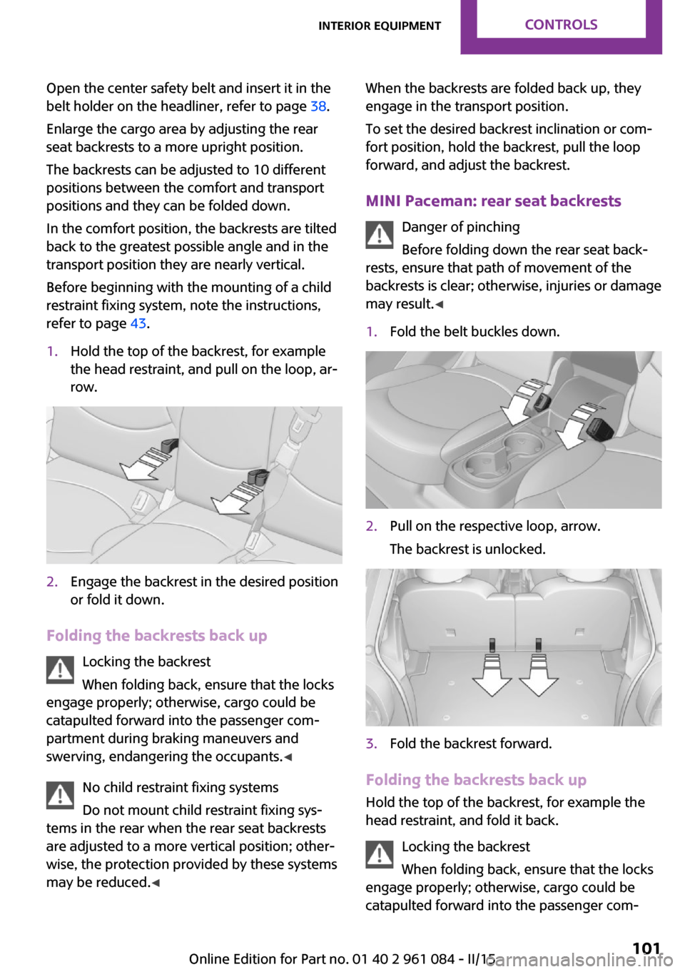
refer to page 43.1.Hold the top of the backrest, for example
the head restraint, and pull on the loop, ar‐
row.2.Engage the backrest in the desired position
or fold it down.
Folding the backrests back up
Locking the backrest
When folding back, ensure that the locks
engage properly; otherwise, cargo could be
catapulted forward into the passenger com‐
partment during braking maneuvers and
swerving, endangering the occupants. ◀
No child restraint fixing systems
Do not mount child restraint fixing sys‐
tems in the rear when the rear seat backrests
are adjusted to a more vertical position; other‐
wise, the protection provided by these systems
may be reduced. ◀
When the backrests are folded back up, they
engage in the transport position.
To set the desired backrest inclination or com‐
fort position, hold the backrest, pull the loop
forward, and adjust the backrest.
MINI Paceman: rear seat backrests Danger of pinching
Before folding down the rear seat back‐
rests, ensure that path of movement of the
backrests is clear; otherwise, injuries or damage
may result. ◀1.Fold the belt buckles down.2.Pull on the respective loop, arrow.
The backrest is unlocked.3.Fold the backrest forward.
Folding the backrests back up Hold the top of the backrest, for example the
head restraint, and fold it back.
Locking the backrest
When folding back, ensure that the locks
engage properly; otherwise, cargo could be
catapulted forward into the passenger com‐
Seite 101Interior equipmentCONTROLS101
Online Edition for Part no. 01 40 2 961 084 - II/15
Page 104 of 223
partment during braking maneuvers and
swerving, endangering the occupants. ◀
Flat loading floor Maximum load
Do not exceed the maximum load of
330 lbs, 150 kg, on the loading floor; otherwise,
damage may result. ◀
Access to storage area
A storage area for items like the partition net is
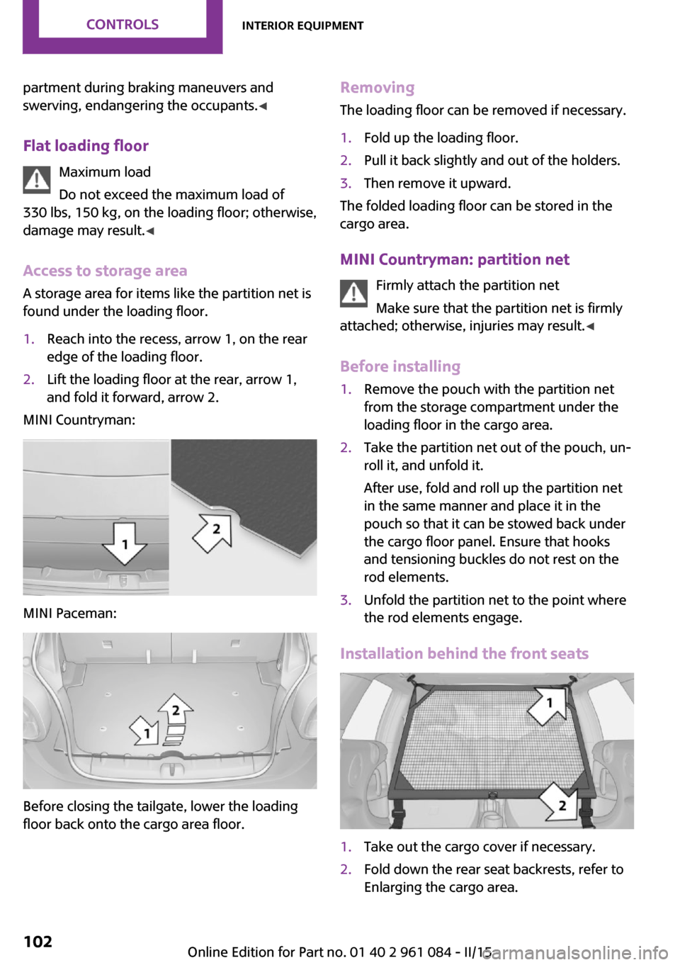
found under the loading floor.1.Reach into the recess, arrow 1, on the rear
edge of the loading floor.2.Lift the loading floor at the rear, arrow 1,
and fold it forward, arrow 2.
MINI Countryman:
MINI Paceman:
Before closing the tailgate, lower the loading
floor back onto the cargo area floor.
Removing
The loading floor can be removed if necessary.1.Fold up the loading floor.2.Pull it back slightly and out of the holders.3.Then remove it upward.
The folded loading floor can be stored in the
cargo area.
MINI Countryman: partition net Firmly attach the partition net
Make sure that the partition net is firmly
attached; otherwise, injuries may result. ◀
Before installing
1.Remove the pouch with the partition net
from the storage compartment under the
loading floor in the cargo area.2.Take the partition net out of the pouch, un‐
roll it, and unfold it.
After use, fold and roll up the partition net
in the same manner and place it in the
pouch so that it can be stowed back under
the cargo floor panel. Ensure that hooks
and tensioning buckles do not rest on the
rod elements.3.Unfold the partition net to the point where
the rod elements engage.
Installation behind the front seats
1.Take out the cargo cover if necessary.2.Fold down the rear seat backrests, refer to
Enlarging the cargo area.Seite 102CONTROLSInterior equipment102
Online Edition for Part no. 01 40 2 961 084 - II/15
Page 105 of 223
3.Insert the retaining pins of the partition net
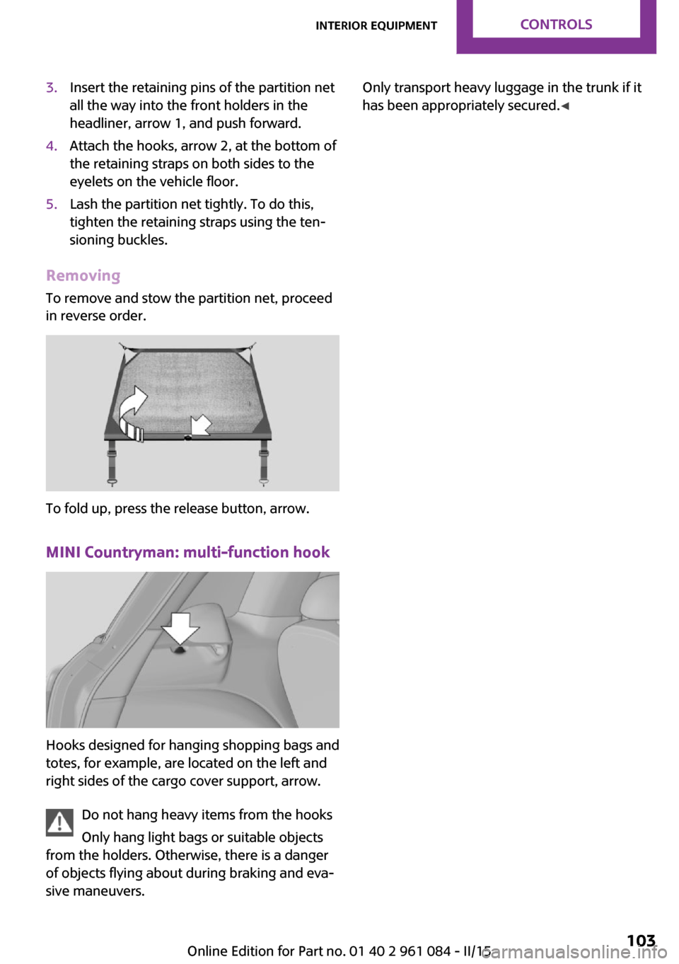
all the way into the front holders in the
headliner, arrow 1, and push forward.4.Attach the hooks, arrow 2, at the bottom of
the retaining straps on both sides to the
eyelets on the vehicle floor.5.Lash the partition net tightly. To do this,
tighten the retaining straps using the ten‐
sioning buckles.
Removing
To remove and stow the partition net, proceed
in reverse order.
To fold up, press the release button, arrow.
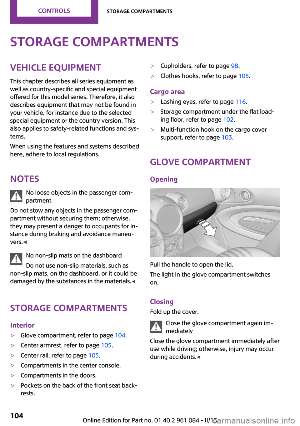
MINI Countryman: multi-function hook
Hooks designed for hanging shopping bags and
totes, for example, are located on the left and
right sides of the cargo cover support, arrow.
Do not hang heavy items from the hooks
Only hang light bags or suitable objects
from the holders. Otherwise, there is a danger
of objects flying about during braking and eva‐
sive maneuvers.
Only transport heavy luggage in the trunk if it
has been appropriately secured. ◀Seite 103Interior equipmentCONTROLS103
Online Edition for Part no. 01 40 2 961 084 - II/15
Page 106 of 223
Storage compartmentsVehicle equipment
This chapter describes all series equipment as
well as country-specific and special equipment
offered for this model series. Therefore, it also
describes equipment that may not be found in
your vehicle, for instance due to the selected
special equipment or the country version. This
also applies to safety-related functions and sys‐
tems.
When using the features and systems described
here, adhere to local regulations.
Notes No loose objects in the passenger com‐
partment
Do not stow any objects in the passenger com‐
partment without securing them; otherwise,
they may present a danger to occupants for in‐
stance during braking and avoidance maneu‐
vers. ◀
No non-slip mats on the dashboard
Do not use non-slip materials, such as
non-slip mats, on the dashboard, or it could be
damaged by the substances in the materials. ◀
Storage compartments
Interior▷Glove compartment, refer to page 104.▷Center armrest, refer to page 105.▷Center rail, refer to page 105.▷Compartments in the center console.▷Compartments in the doors.▷Pockets on the back of the front seat back‐
rests.▷Cupholders, refer to page 98.▷Clothes hooks, refer to page 105.
Cargo area
▷Lashing eyes, refer to page 116.▷Storage compartment under the flat load‐
ing floor, refer to page 102.▷Multi-function hook on the cargo cover
support, refer to page 103.
Glove compartment
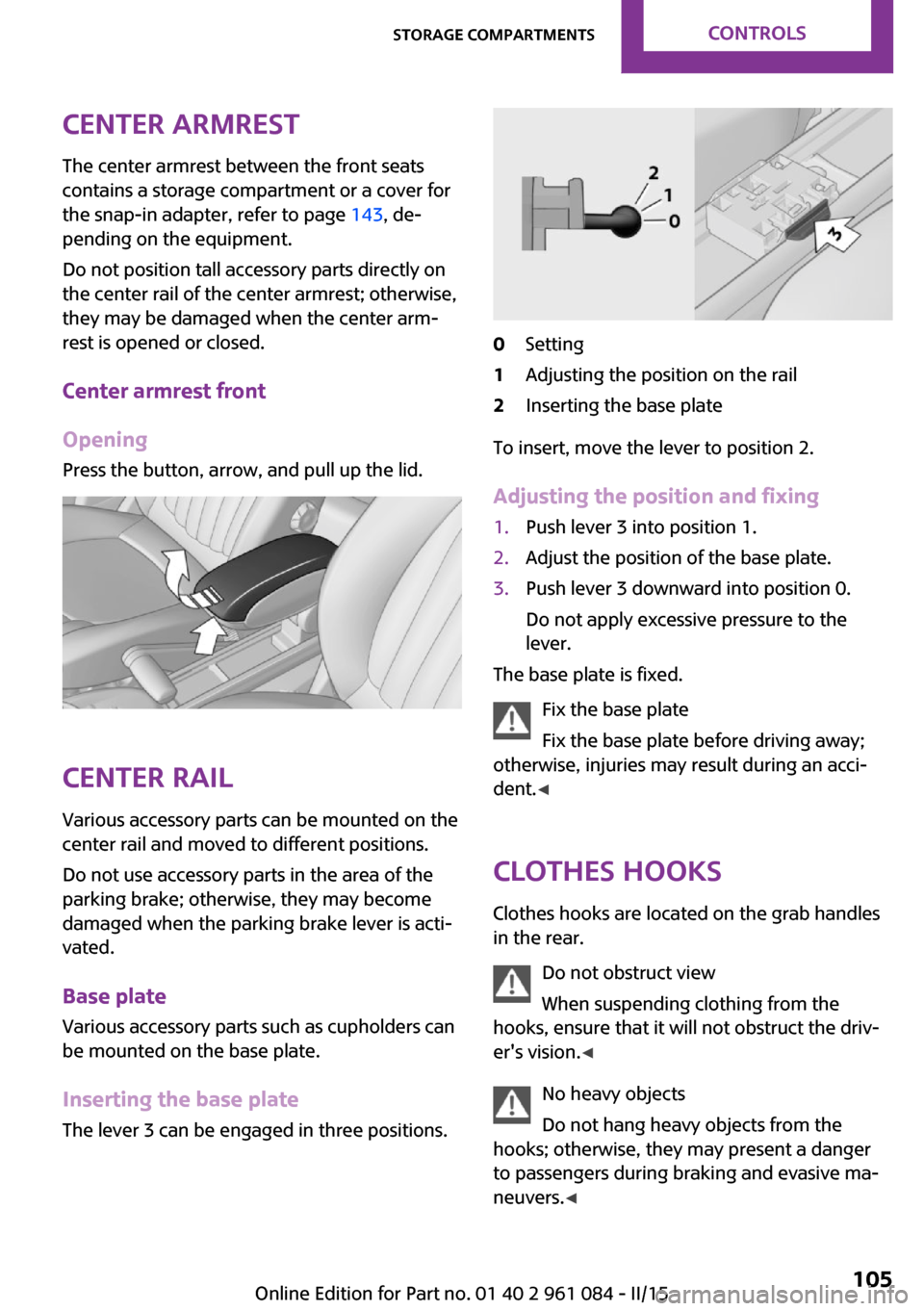
Opening
Pull the handle to open the lid.
The light in the glove compartment switches
on.
Closing Fold up the cover.
Close the glove compartment again im‐
mediately
Close the glove compartment immediately after
use while driving; otherwise, injury may occur
during accidents. ◀
Seite 104CONTROLSStorage compartments104
Online Edition for Part no. 01 40 2 961 084 - II/15
Page 107 of 223
Center armrestThe center armrest between the front seats
contains a storage compartment or a cover for
the snap-in adapter, refer to page 143, de‐
pending on the equipment.
Do not position tall accessory parts directly on
the center rail of the center armrest; otherwise,
they may be damaged when the center arm‐
rest is opened or closed.
Center armrest front
Opening
Press the button, arrow, and pull up the lid.
Center rail
Various accessory parts can be mounted on the
center rail and moved to different positions.
Do not use accessory parts in the area of the
parking brake; otherwise, they may become
damaged when the parking brake lever is acti‐
vated.
Base plate
Various accessory parts such as cupholders can
be mounted on the base plate.
Inserting the base plate The lever 3 can be engaged in three positions.
0Setting1Adjusting the position on the rail2Inserting the base plate
To insert, move the lever to position 2.
Adjusting the position and fixing
1.Push lever 3 into position 1.2.Adjust the position of the base plate.3.Push lever 3 downward into position 0.
Do not apply excessive pressure to the
lever.
The base plate is fixed.
Fix the base plate
Fix the base plate before driving away;
otherwise, injuries may result during an acci‐
dent. ◀
Clothes hooks Clothes hooks are located on the grab handles
in the rear.
Do not obstruct view
When suspending clothing from the
hooks, ensure that it will not obstruct the driv‐
er's vision. ◀
No heavy objects
Do not hang heavy objects from the
hooks; otherwise, they may present a danger
to passengers during braking and evasive ma‐
neuvers. ◀
Seite 105Storage compartmentsCONTROLS105
Online Edition for Part no. 01 40 2 961 084 - II/15
Page 108 of 223
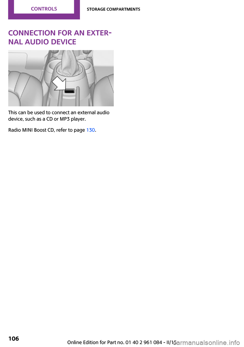
Connection for an exter‐
nal audio device
This can be used to connect an external audio
device, such as a CD or MP3 player.
Radio MINI Boost CD, refer to page 130.
Seite 106CONTROLSStorage compartments106
Online Edition for Part no. 01 40 2 961 084 - II/15
Page 109 of 223
Seite 107Storage compartmentsCONTROLS107
Online Edition for Part no. 01 40 2 961 084 - II/15
Page 110 of 223

DRIVE ME.
Online Edition for Part no. 01 40 2 961 084 - II/15