service MINI Paceman 2015 User Guide
[x] Cancel search | Manufacturer: MINI, Model Year: 2015, Model line: Paceman, Model: MINI Paceman 2015Pages: 223, PDF Size: 5.51 MB
Page 62 of 223
Information in detail
Range
Displays the estimated cruising range available
with the remaining fuel.
It is calculated based on your driving style over
the last 18 miles/30 km.
Average fuel consumption This is calculated for the period during which
the engine is running.
To reset the average consumption: press the
button on the turn indicator lever for ap‐
prox. 2 seconds.
Current fuel consumption Displays the current fuel consumption. You can
check whether you are currently driving in an
efficient and environmentally-friendly manner.
Average speed Periods in which the vehicle was parked and
the engine was switched off manually are not
included in the average speed calculations.
To reset the average speed: press the button
on the turn indicator lever for approx. 2 sec‐
onds.
Radio MINI Boost CD: displays on the
radio
Some computer functions can also be shown
on the radio display, refer to page 125.
Settings and information Operating conceptSome settings and information can only be cre‐
ated or opened while the ignition is switched
on, the vehicle is standing, and the doors are
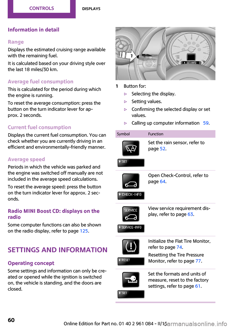
closed.1Button for:▷Selecting the display.▷Setting values.▷Confirming the selected display or set
values.▷Calling up computer information 59.SymbolFunctionSet the rain sensor, refer to
page 52.Open Check-Control, refer to
page 64.View service requirement dis‐
play, refer to page 63.Initialize the Flat Tire Monitor,
refer to page 74.
Resetting the Tire Pressure
Monitor, refer to page 77.Set the formats and units of
measure, reset to the factory
settings, refer to page 61.Seite 60CONTROLSDisplays60
Online Edition for Part no. 01 40 2 961 084 - II/15
Page 65 of 223
Service requirements
The remaining driving distance and the date of
the next scheduled service are displayed briefly
immediately after you start the engine or
switch on the ignition.
The current service requirements can be read
out from the remote control by the service spe‐
cialist.
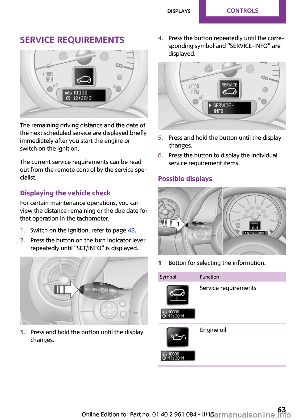
Displaying the vehicle check
For certain maintenance operations, you can
view the distance remaining or the due date for
that operation in the tachometer.
1.Switch on the ignition, refer to page 48.2.Press the button on the turn indicator lever
repeatedly until "SET/INFO" is displayed.3.Press and hold the button until the display
changes.4.Press the button repeatedly until the corre‐
sponding symbol and "SERVICE-INFO" are
displayed.5.Press and hold the button until the display
changes.6.Press the button to display the individual
service requirement items.
Possible displays
1Button for selecting the information.SymbolFunctionService requirementsEngine oilSeite 63DisplaysCONTROLS63
Online Edition for Part no. 01 40 2 961 084 - II/15
Page 74 of 223
Protective action
Airbags are not triggered in every impact situa‐
tion, e.g., in less severe accidents or rear-end
collisions.
Information on how to ensure the opti‐
mal protective effect of the airbags▷Keep at a distance from the airbags.▷Always grasp the steering wheel on the
steering wheel rim, holding your hands at
the 3 o'clock and 9 o'clock positions, to
keep the danger of injury to your hands or
arms as low as possible if the airbag is trig‐
gered.▷There should be no people, animals, or ob‐
jects between an airbag and a person.▷Do not use the cover of the front airbag on
the front passenger side as a storage area.▷Keep the dashboard and window on the
front passenger side clear, i.e., do not cover
with adhesive labels or coverings, and do
not attach holders or cables such as for
navigation instruments and mobile phones.▷Make sure that the front passenger is sitting
correctly, i.e., keeps his or her feet and legs
in the footwell; otherwise, leg injuries can
occur if the front airbag is triggered.▷Do not place slip covers, seat cushions or
other objects on the front passenger seat
that are not approved specifically for seats
with integrated side airbags.▷Do not hang pieces of clothing, such as
jackets, over the backrests.▷Make sure that occupants keep their heads
away from the side airbag and do not rest
against the head airbag; otherwise, injuries
can occur if the airbags are triggered.▷Do not remove the airbag restraint system.▷Do not remove the steering wheel.▷Do not apply adhesive materials to the air‐
bag cover panels, cover them or modify
them in any way.▷Never modify either the individual compo‐
nents or the wiring in the airbag system.
This also applies to steering wheel covers,
the dashboard, the seats, the roof pillars
and the sides of the headliner. ◀
Even when all instructions are followed closely,
injury from contact with the airbags cannot be
ruled out in certain situations.
The ignition and inflation noise may lead to
short-term and, in most cases, temporary hear‐
ing impairment in sensitive individuals.
In the case of a malfunction, deactivation
and after triggering of the airbags
Do not touch the individual components imme‐
diately after the system has been triggered;
otherwise, there is the danger of burns.
Only have the airbags checked, repaired or dis‐
mantled and the airbag generator scrapped by
your service center or a workshop that has the
necessary authorization for handling explo‐
sives.
Non-professional attempts to service the sys‐
tem could lead to failure in an emergency or
undesired triggering of the airbag, either of
which could result in injury. ◀
Warning notices and information about the air‐
bags can also be found on the sun visors.
Automatic deactivation of the front
passenger airbags
The system determines whether the front pas‐
senger seat is occupied by measuring the elec‐
trical resistance of the human body.
The front, side, and knee airbags on the front
passenger side are activated or deactivated ac‐
cordingly by the system.
The indicator lamp above the interior rearview
mirror, refer to page 73, shows the current
status of the front passenger airbags, deacti‐
vated or activated.
Seite 72CONTROLSSafety72
Online Edition for Part no. 01 40 2 961 084 - II/15
Page 77 of 223
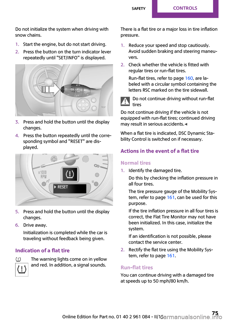
Do not initialize the system when driving with
snow chains.1.Start the engine, but do not start driving.2.Press the button on the turn indicator lever
repeatedly until "SET/INFO" is displayed.3.Press and hold the button until the display
changes.4.Press the button repeatedly until the corre‐
sponding symbol and "RESET" are dis‐
played.5.Press and hold the button until the display
changes.6.Drive away.
Initialization is completed while the car is
traveling without feedback being given.
Indication of a flat tire
The warning lights come on in yellow
and red. In addition, a signal sounds.
There is a flat tire or a major loss in tire inflation
pressure.1.Reduce your speed and stop cautiously.
Avoid sudden braking and steering maneu‐
vers.2.Check whether the vehicle is fitted with
regular tires or run-flat tires.
Run-flat tires, refer to page 160, are la‐
beled with a circular symbol containing the
letters RSC marked on the tire sidewall.
Do not continue driving without run-flat
tires
Do not continue driving if the vehicle is not
equipped with run-flat tires; continued driving
may result in serious accidents. ◀
When a flat tire is indicated, DSC Dynamic Sta‐
bility Control is switched on if necessary.
Actions in the event of a flat tire
Normal tires
1.Identify the damaged tire.
Do this by checking the inflation pressure in
all four tires.
The tire pressure gauge of the Mobility Sys‐
tem, refer to page 161, can be used for this
purpose.
If the tire inflation pressure in all four tires is
correct, the Flat Tire Monitor may not have
been initialized. In this case, initialize the
system.
If an identification is not possible, please
contact the service center.2.Rectify the flat tire using the Mobility Sys‐
tem, refer to page 161.
Run-flat tires
You can continue driving with a damaged tire
at speeds up to 50 mph/80 km/h.
Seite 75SafetyCONTROLS75
Online Edition for Part no. 01 40 2 961 084 - II/15
Page 78 of 223
Continued driving with a flat tire
If continuing to drive with a damaged tire:1.Avoid sudden braking and steering maneu‐
vers.2.Do not exceed a speed of 50 mph/80 km/h.3.At the next opportunity, check the inflation
pressure in all four tires.
If the tire inflation pressure in all four tires is
correct, the Flat Tire Monitor may not have
been initialized. In this case, initialize the
system.
Possible driving distance with complete loss of
tire inflation pressure:
The possible driving distance after a loss of tire
inflation pressure depends on the cargo load
and the driving style and conditions.
For a vehicle containing an average load, the
possible driving distance is ap‐
prox. 50 miles/80 km.
When the vehicle is driven with a damaged tire,
its handling characteristics change, e.g., re‐
duced lane stability during braking, a longer
braking distance, and altered self-steering
properties. Adjust your driving style accord‐
ingly. Avoid abrupt steering maneuvers or driv‐
ing over obstacles, e. g., curbs, potholes, etc.
Because the possible driving distance depends
on how the vehicle is used during the trip, the
actual distance may be smaller or greater de‐
pending on the driving speed, road conditions,
external temperature, cargo load, etc.
Continued driving with a flat tire
Drive moderately and do not exceed a
speed of 50 mph/80 km/h.
A loss of tire inflation pressure results in a
change in the handling characteristics, e.g., re‐
duced lane stability during braking, a longer
braking distance and altered self-steering prop‐
erties. ◀
Final tire failure
Vibrations or loud noises while driving
can indicate the final failure of the tire. Reduce
speed and stop; otherwise, pieces of the tire
could come loose and cause an accident. Do
not continue driving, and contact your service
center. ◀
Tire Pressure Monitor
TPM
The concept
The system monitors the tire pressure in the
four mounted tires. The system notifies you if
there is a significant loss of pressure in one or
more tires. Sensors in the tire valves measure
the tire pressure.
Notes Tire damage caused by external influen‐
ces
Sudden tire damage caused by external influ‐
ences cannot be indicated in advance. ◀
To operate the system, also note the additional
information and instructions contained under
Tire inflation pressure, refer to page 152.
Functional requirements
The system must have been reset while the in‐
flation pressure was correct; otherwise, it may
not reliably signal a loss in pressure.
Perform a system reset after adjusting the tire
inflation pressure to a new value and after
changing a tire or wheel
Always use wheels with TPM electronics to en‐
sure that the system will operate properly.Seite 76CONTROLSSafety76
Online Edition for Part no. 01 40 2 961 084 - II/15
Page 80 of 223
Do not continue driving without run-flat
tires
Do not continue driving if the vehicle is not
equipped with run-flat tires; continued driving
may result in serious accidents. ◀
When a low inflation pressure is indicated, DSC
Dynamic Stability Control is switched on if nec‐
essary.
Actions in the event of a flat tire Normal tires1.Identify the damaged tire.
Do this by checking the air pressure in all
four tires. The tire pressure gauge of the
Mobility System, refer to page 161, can be
used for this purpose.
If the tire inflation pressure in all four tires is
correct, the Tire Pressure Monitor may not
have been reset. Reset the system.
If an identification is not possible, please
contact the service center.2.Rectify the flat tire using the Mobility Sys‐
tem, refer to page 161.
Use of tire sealant, e.g., the Mobility Sys‐
tem, may damage the TPM wheel electron‐
ics. In this case, have the electronics
checked at the next opportunity and have
them replaced if necessary.
Run-flat tires
You can continue driving with a damaged tire
at speeds up to 50 mph/80 km/h.
Do not continue driving without run-flat
tires
Do not continue driving if the vehicle is not
equipped with run-flat tires; continued driving
may result in serious accidents. ◀
Continued driving with a flat tire
If continuing to drive with a damaged tire:1.Avoid sudden braking and steering maneu‐
vers.2.Do not exceed a speed of 50 mph/80 km/h.3.Check the air pressure in all four tires at the
next opportunity.
If the tire inflation pressure in all four tires is
correct, the Tire Pressure Monitor may not
have been reset. Reset the system.
Possible driving distance with complete loss of
tire inflation pressure:
The possible driving distance after a loss of tire
inflation pressure depends on the cargo load
and the driving style and conditions.
For a vehicle containing an average load, the
possible driving distance is ap‐
prox. 50 miles/80 km.
When the vehicle is driven with a damaged tire,
its handling characteristics change, e.g., re‐
duced lane stability during braking, a longer
braking distance, and altered self-steering
properties. Adjust your driving style accord‐
ingly. Avoid abrupt steering maneuvers or driv‐
ing over obstacles, e. g., curbs, potholes, etc.
Because the possible driving distance depends
on how the vehicle is used during the trip, the
actual distance may be smaller or greater de‐
pending on the driving speed, road conditions,
external temperature, cargo load, etc.
Continued driving with a flat tire
Drive moderately and do not exceed a
speed of 50 mph/80 km/h.
A loss of tire inflation pressure results in a
change in the handling characteristics, e.g., re‐
duced lane stability during braking, a longer
braking distance and altered self-steering prop‐
erties. ◀
Seite 78CONTROLSSafety78
Online Edition for Part no. 01 40 2 961 084 - II/15
Page 81 of 223
Final tire failure
Vibrations or loud noises while driving
can indicate the final failure of the tire. Reduce
speed and stop; otherwise, pieces of the tire
could come loose and cause an accident. Do
not continue driving, and contact your service
center. ◀
Message indicating that the inflation
pressure needs to be checked
The yellow warning light lights up.
A Check Control message is displayed.▷The system has detected that a wheel was
changed but a reset was not performed.▷The tire was not inflated according to speci‐
fications.▷The tire pressure has dropped since the last
confirmation.
In this case:
▷Check the tire inflation pressure and correct
it if necessary.▷After changing a wheel, reset the system.
System limits
The system will not function properly if a reset
was not performed, e.g., it may identify a tire as
flat although the tire is filled to the correct infla‐
tion pressure.
The tire pressure depends on the temperature
of the tire. An increase in the tire temperature,
e.g., while driving or due to sunlight, increases
the tire inflation pressure. The tire pressure de‐
creases when the tire temperature drops. In
case of severe temperature drops, this behavior
may lead to a warning on account of the de‐
fined warning limits.
Malfunction The yellow warning light flashes yellow
and then lights up continuously.
A Check Control message is displayed.
A flat tire or tire inflation pressure loss cannot
be detected.
Display in the following situations:▷A wheel without TPM electronics is
mounted, e.g., a compact wheel:
Have the system checked by the service
center if necessary.▷Malfunction:
Have the system checked by the service
center.▷TPM was unable to complete the reset.
Reset the system again.
The yellow warning light flashes and
then lights up continuously.
A Check Control message is displayed.
A flat tire or tire inflation pressure loss cannot
be detected.
Display in the following situation:
▷Disturbance by other systems or devices
with the same radio frequency:
After leaving the area of the disturbance,
the system automatically becomes active
again.
Declaration according to NHTSA/FMVSS
138 Tire Pressure Monitoring Systems
Each tire, including the spare (if provided)
should be checked monthly when cold and in‐
flated to the inflation pressure recommended
by the vehicle manufacturer on the vehicle
placard or tire inflation pressure label (If your
vehicle has tires of a different size than the size indicated on the vehicle placard or tire inflation
pressure label, you should determine the
proper tire inflation pressure for those tires.).
As an added safety feature, your vehicle has
been equipped with a tire pressure monitoring
system (TPMS) that illuminates a low tire pres‐
sure telltale when one or more of your tires is
significantly under-inflated. Accordingly, when
the low tire pressure telltale illuminates, you
Seite 79SafetyCONTROLS79
Online Edition for Part no. 01 40 2 961 084 - II/15
Page 92 of 223
4.Deactivate recirculated air mode.5.Switch on the windshield heating if neces‐
sary.6.Switch on the rear window defroster if nec‐
essary.
Microfilter
The microfilter traps dust and pollen. The mi‐
crofilter is changed by the service center during
routine maintenance work.
Microfilter/activated-charcoal filter
The microfilter traps dust and pollen. The acti‐
vated-charcoal filter provides additional protec‐
tion by filtering gaseous pollutants from the
outside air. The service center replaces this
combined filter during routine maintenance.
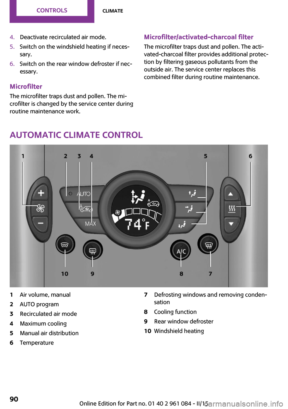
Automatic climate control
1Air volume, manual2AUTO program3Recirculated air mode4Maximum cooling5Manual air distribution6Temperature7Defrosting windows and removing conden‐
sation8Cooling function9Rear window defroster10Windshield heatingSeite 90CONTROLSClimate90
Online Edition for Part no. 01 40 2 961 084 - II/15
Page 94 of 223
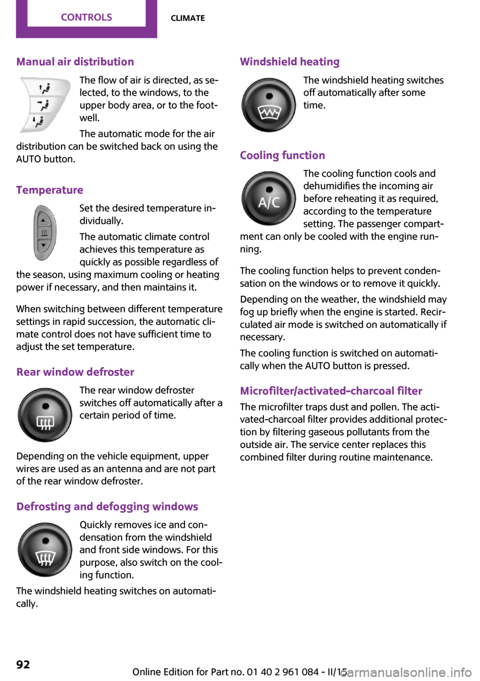
Manual air distributionThe flow of air is directed, as se‐
lected, to the windows, to the
upper body area, or to the foot‐
well.
The automatic mode for the air
distribution can be switched back on using the
AUTO button.
Temperature Set the desired temperature in‐
dividually.
The automatic climate control
achieves this temperature as
quickly as possible regardless of
the season, using maximum cooling or heating power if necessary, and then maintains it.
When switching between different temperature
settings in rapid succession, the automatic cli‐
mate control does not have sufficient time to
adjust the set temperature.
Rear window defroster The rear window defroster
switches off automatically after a
certain period of time.
Depending on the vehicle equipment, upper
wires are used as an antenna and are not part
of the rear window defroster.
Defrosting and defogging windows Quickly removes ice and con‐
densation from the windshield
and front side windows. For this
purpose, also switch on the cool‐
ing function.
The windshield heating switches on automati‐
cally.Windshield heating
The windshield heating switches
off automatically after some
time.
Cooling function The cooling function cools and
dehumidifies the incoming air
before reheating it as required,
according to the temperature
setting. The passenger compart‐
ment can only be cooled with the engine run‐
ning.
The cooling function helps to prevent conden‐
sation on the windows or to remove it quickly.
Depending on the weather, the windshield may
fog up briefly when the engine is started. Recir‐
culated air mode is switched on automatically if
necessary.
The cooling function is switched on automati‐
cally when the AUTO button is pressed.
Microfilter/activated-charcoal filterThe microfilter traps dust and pollen. The acti‐
vated-charcoal filter provides additional protec‐
tion by filtering gaseous pollutants from the
outside air. The service center replaces this
combined filter during routine maintenance.Seite 92CONTROLSClimate92
Online Edition for Part no. 01 40 2 961 084 - II/15
Page 96 of 223
Interior equipmentVehicle equipmentThis chapter describes all series equipment as
well as country-specific and special equipment
offered for this model series. Therefore, it also
describes equipment that may not be found in
your vehicle, for instance due to the selected
special equipment or the country version. This
also applies to safety-related functions and sys‐
tems.
When using the features and systems described
here, adhere to local regulations.
Universal garage dooropener
The concept
The universal garage door opener can be used
to operate up to 3 functions in remote-control‐
led systems, such as garage door drives or
lighting systems. The universal garage door
opener replaces up to 3 different hand-held
transmitters. To operate it, the buttons on the
interior rearview mirror must be programmed
for the desired functions. The hand-held trans‐
mitter for the system is needed for the pro‐
gramming procedure.
During programming
During programming and before activat‐
ing a device using the Universal Garage Door
Opener, ensure that there are no people, ani‐
mals, or objects in the range of movement of
the remote-controlled device; otherwise, there
is a risk of injury or damage.
Also follow the safety instructions of the hand-
held transmitter. ◀
Before selling the vehicle, delete the stored
functions for security reasons.Compatibility
If this symbol is printed on the packag‐
ing or in the operating instructions of
the system being operated, the system
is generally compatible with the universal ga‐
rage door opener.
If you have any questions, please contact:▷Your service center.▷www.homelink.com on the Internet.
HomeLink is a registered trademark of the
Gentex Corporation.
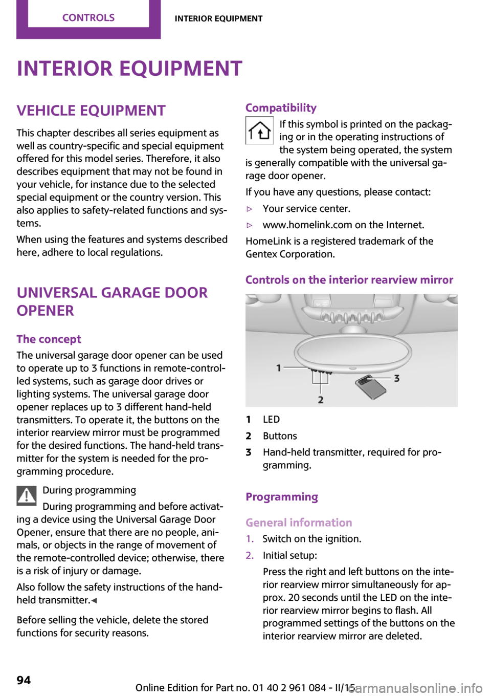
Controls on the interior rearview mirror
1LED2Buttons3Hand-held transmitter, required for pro‐
gramming.
Programming
General information
1.Switch on the ignition.2.Initial setup:
Press the right and left buttons on the inte‐
rior rearview mirror simultaneously for ap‐
prox. 20 seconds until the LED on the inte‐
rior rearview mirror begins to flash. All
programmed settings of the buttons on the
interior rearview mirror are deleted.Seite 94CONTROLSInterior equipment94
Online Edition for Part no. 01 40 2 961 084 - II/15