service MINI Paceman 2015 Owner's Guide
[x] Cancel search | Manufacturer: MINI, Model Year: 2015, Model line: Paceman, Model: MINI Paceman 2015Pages: 223, PDF Size: 5.51 MB
Page 130 of 223
A phone number and the electronic serial
number, ESN, are displayed. The electronic
serial number is required for activation.3.To have the channels activated, call the
phone number.
Deactivating
1. Press the button.2."SAT"3."SAT"
Hold the button down.
A phone number and the electronic serial
number, ESN, are displayed. The electronic
serial number is required for deactivation.4.To have the channels deactivated, call the
phone number.
Selecting and storing a channel
1. Press the button.2."SAT"3."CAT"4.Select the desired category.5.Select the desired channel.
To display all channels:
"ALL"
To store a channel:
1. Select the symbol.2."SAT"
Press the button repeatedly until the de‐
sired memory level, SAT 1 or SAT 2, is
reached.3."1" ... "6"
Press and hold the function button under
the desired memory location until the
channel is audible again after a brief inter‐
ruption.
Changing to the current channel
"CURR"
Additional information
The name of the channel and additional infor‐
mation on the current track are displayed, such
as the name of the artist.1.Select the desired channel.2."INFO"
Changing the channel using the buttons
Press the button for the corre‐
sponding direction. The next enabled channel
is opened.
Search
1. Press and hold the button for
the corresponding direction. The activated
channels appear on the display one after
the other.2.Release the button to select the displayed
channel.
Notes
When there is a signal blockage or the trans‐
mission is suspended momentarily for more
than 4 seconds, a message will appear on the
display.
Service may be interrupted or unavailable for
specific reasons such as environmental or topo‐
graphic conditions and others that Satellite
Radio cannot directly control. Signal may not be
available under tunnels, in parking garages,
next to tall buildings, nearby trees with dense
foliage, nearby mountains or other possible
strong sources of radio interference. Service
should resume normally after the source of sig‐
nal unavailability has been cleared.
CD player
Loading the CD player Insert the CD into the CD drive with the printed
side up.
Seite 128ENTERTAINMENTRadio MINI Boost CD128
Online Edition for Part no. 01 40 2 961 084 - II/15
Page 133 of 223
Connecting
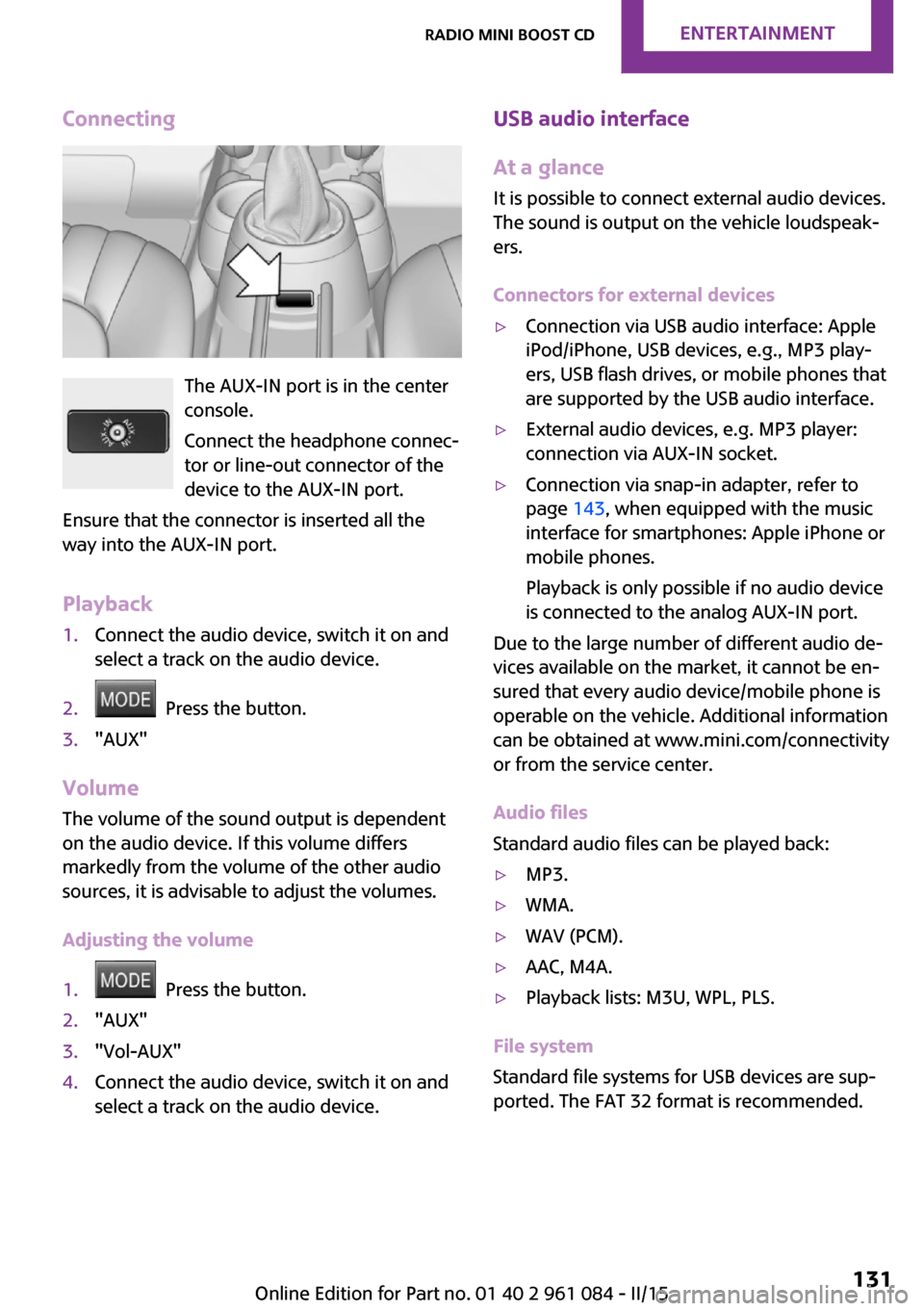
The AUX-IN port is in the center
console.
Connect the headphone connec‐
tor or line-out connector of the
device to the AUX-IN port.
Ensure that the connector is inserted all the
way into the AUX-IN port.
Playback
1.Connect the audio device, switch it on and
select a track on the audio device.2. Press the button.3."AUX"
Volume
The volume of the sound output is dependent
on the audio device. If this volume differs
markedly from the volume of the other audio
sources, it is advisable to adjust the volumes.
Adjusting the volume
1. Press the button.2."AUX"3."Vol-AUX"4.Connect the audio device, switch it on and
select a track on the audio device.USB audio interface
At a glance
It is possible to connect external audio devices.
The sound is output on the vehicle loudspeak‐
ers.
Connectors for external devices▷Connection via USB audio interface: Apple
iPod/iPhone, USB devices, e.g., MP3 play‐
ers, USB flash drives, or mobile phones that
are supported by the USB audio interface.▷External audio devices, e.g. MP3 player:
connection via AUX-IN socket.▷Connection via snap-in adapter, refer to
page 143, when equipped with the music
interface for smartphones: Apple iPhone or
mobile phones.
Playback is only possible if no audio device
is connected to the analog AUX-IN port.
Due to the large number of different audio de‐
vices available on the market, it cannot be en‐
sured that every audio device/mobile phone is
operable on the vehicle. Additional information
can be obtained at www.mini.com/connectivity
or from the service center.
Audio files
Standard audio files can be played back:
▷MP3.▷WMA.▷WAV (PCM).▷AAC, M4A.▷Playback lists: M3U, WPL, PLS.
File system
Standard file systems for USB devices are sup‐
ported. The FAT 32 format is recommended.
Seite 131Radio MINI Boost CDENTERTAINMENT131
Online Edition for Part no. 01 40 2 961 084 - II/15
Page 134 of 223
Connecting
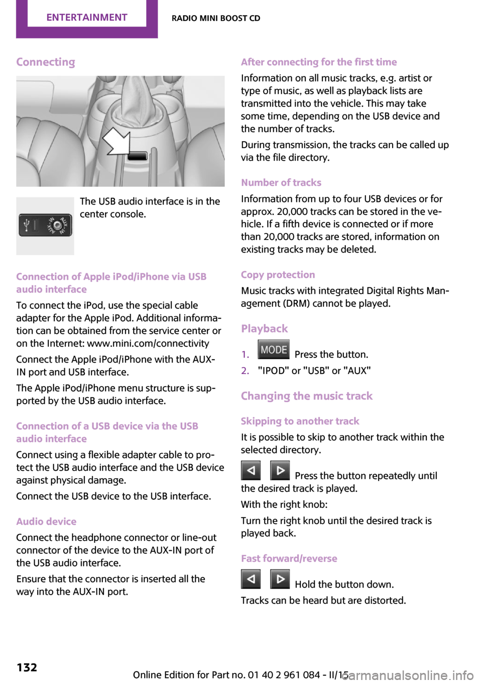
The USB audio interface is in the
center console.
Connection of Apple iPod/iPhone via USB
audio interface
To connect the iPod, use the special cable
adapter for the Apple iPod. Additional informa‐
tion can be obtained from the service center or
on the Internet: www.mini.com/connectivity
Connect the Apple iPod/iPhone with the AUX-
IN port and USB interface.
The Apple iPod/iPhone menu structure is sup‐
ported by the USB audio interface.
Connection of a USB device via the USB
audio interface
Connect using a flexible adapter cable to pro‐
tect the USB audio interface and the USB device
against physical damage.
Connect the USB device to the USB interface.
Audio device
Connect the headphone connector or line-out
connector of the device to the AUX-IN port of
the USB audio interface.
Ensure that the connector is inserted all the
way into the AUX-IN port.
After connecting for the first time
Information on all music tracks, e.g. artist or
type of music, as well as playback lists are
transmitted into the vehicle. This may take
some time, depending on the USB device and
the number of tracks.
During transmission, the tracks can be called up
via the file directory.
Number of tracks
Information from up to four USB devices or for
approx. 20,000 tracks can be stored in the ve‐
hicle. If a fifth device is connected or if more
than 20,000 tracks are stored, information on
existing tracks may be deleted.
Copy protection
Music tracks with integrated Digital Rights Man‐
agement (DRM) cannot be played.
Playback1. Press the button.2."IPOD" or "USB" or "AUX"
Changing the music track
Skipping to another track
It is possible to skip to another track within the
selected directory.
Press the button repeatedly until
the desired track is played.
With the right knob:
Turn the right knob until the desired track is
played back.
Fast forward/reverse
Hold the button down.
Tracks can be heard but are distorted.
Seite 132ENTERTAINMENTRadio MINI Boost CD132
Online Edition for Part no. 01 40 2 961 084 - II/15
Page 138 of 223
TelephoneVehicle equipment
This chapter describes all series equipment as
well as country-specific and special equipment
offered for this model series. Therefore, it also
describes equipment that may not be found in
your vehicle, for instance due to the selected
special equipment or the country version. This
also applies to safety-related functions and sys‐
tems.
When using the features and systems described
here, adhere to local regulations.
At a glance
The concept
Mobile phones can be connected with the vehi‐
cle via Bluetooth.
After a suitable mobile phone is paired with the
vehicle once, you can operate the mobile
phone via the radio, the buttons on the steer‐
ing wheel, and via voice activation.
Bluetooth® is a registered trademark of Blue‐
tooth® SIG, Inc.
Certain functions may need to be enabled by
the mobile phone provider or service provider.
Using the mobile phone while driving
Make entries only when traffic and road
conditions allow. Do not hold the mobile phone
in your hand while you are driving; use the
hands-free system instead. If you do not ob‐
serve this precaution, you can endanger the ve‐
hicle occupants and other road users. ◀
Snap-in adapter
The snap-in adapter is used to:▷Hold the mobile phone.▷Recharge the battery.▷Connect the mobile phone to an outside
antenna of the vehicle.
This provides for better network reception
and consistent sound quality.
Do not operate a mobile phone that is con‐
nected to the vehicle on the mobile phone key‐
pad, as this may lead to a malfunction.
Approved mobile phones
Details on which mobile phones with a Blue‐
tooth interface are supported by the mobile
phone preparation package can be obtained at
www.mini.com/connectivity.
Notes At high temperatures, the charging function of
the mobile phone may be limited and functions
may not be executed.
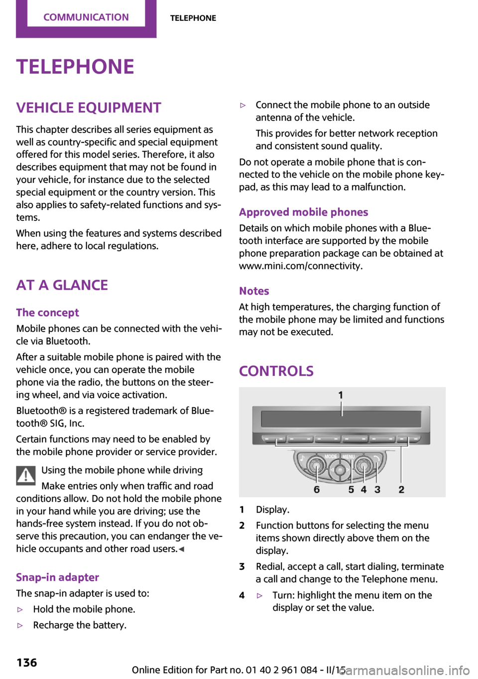
Controls
1Display.2Function buttons for selecting the menu
items shown directly above them on the
display.3Redial, accept a call, start dialing, terminate
a call and change to the Telephone menu.4▷Turn: highlight the menu item on the
display or set the value.Seite 136COMMUNICATIONTelephone136
Online Edition for Part no. 01 40 2 961 084 - II/15
Page 142 of 223
If all points in this list have been checked and
the required function is still not available, con‐
tact Customer Relations or the service center.
Controls▷Accept/reject a call.▷Dial a phone number.▷Dial a phone number from the phone book.▷Dial a stored phone number, such as from
the list of accepted calls.▷End the call.
When the ignition and the radio ready state are
switched off, such as after the remote control is
removed, an existing call can be continued for
up to 25 minutes on the hands-free system.
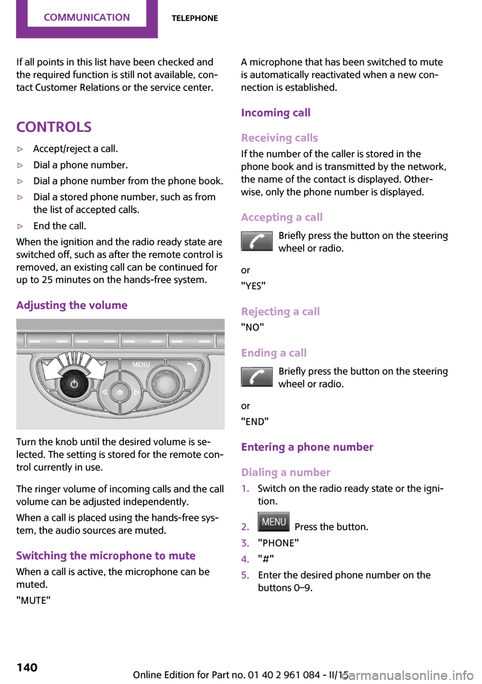
Adjusting the volume
Turn the knob until the desired volume is se‐
lected. The setting is stored for the remote con‐
trol currently in use.
The ringer volume of incoming calls and the call
volume can be adjusted independently.
When a call is placed using the hands-free sys‐
tem, the audio sources are muted.
Switching the microphone to mute
When a call is active, the microphone can be
muted.
"MUTE"
A microphone that has been switched to mute
is automatically reactivated when a new con‐
nection is established.
Incoming call
Receiving calls If the number of the caller is stored in the
phone book and is transmitted by the network,
the name of the contact is displayed. Other‐
wise, only the phone number is displayed.
Accepting a call Briefly press the button on the steering
wheel or radio.
or
"YES"
Rejecting a call
"NO"
Ending a call Briefly press the button on the steering
wheel or radio.
or
"END"
Entering a phone number
Dialing a number1.Switch on the radio ready state or the igni‐
tion.2. Press the button.3."PHONE"4."#"5.Enter the desired phone number on the
buttons 0–9.Seite 140COMMUNICATIONTelephone140
Online Edition for Part no. 01 40 2 961 084 - II/15
Page 144 of 223
4.Enter additional digits on the buttons 0–9.5.Press the right knob to dial the phone num‐
ber.
Dialing a phone number from the phone
book using the buttons on the steering
wheel
1. Press and hold the button to dis‐
play the Telephone menu.2.Press the arrow buttons on the steering
wheel to leaf through the phone book.3. Press the button to dial the phone
number.
Dialing a phone number stored in a list
To select an entry and establish a connection:
1.Switch on the radio ready state or the igni‐
tion.2. Press the button.3."PHONE"4.Select a list, for instance "TOP8"5.Turn the right knob to select an entry and
press the knob to dial the phone number.
Deleting an individual entry
1.Select an entry from the list.2."DEL"
DTMF suffix dialing
DTMF suffix dialing can be used for gaining ac‐
cess to network services or for controlling devi‐
ces, e.g., to make a remote inquiry of an an‐
swering machine. The DTMF code is needed for
this purpose.
This function is only available if a connection
exists and if the hands-free system is being
used.
1."KEYPAD"2.Enter the DTMF code on the buttons 0–9.3.If necessary, press and hold the function
button on the right or left to enter special
characters.
Displaying the call duration
During a call:
"DURAT"
Hands-free system
General information
Calls that are being made on the hands-free
system can be continued on the mobile phone
and vice versa.
From the mobile phone to the hands-
free system
Calls that were begun outside of the Bluetoothrange of the vehicle can be continued on the
hands-free system with the ignition switched
on.
Depending on the mobile phone, the system
automatically switches to the hands-free sys‐
tem.
If the system does not switch over automati‐
cally, follow the instructions on the mobile
phone display; refer also to the mobile phone
operating instructions.
From the hands-free system to the
mobile phone
Calls that are made on the hands-free system
can in some cases be continued on the mobile
phone; this depends on the mobile phone.
Follow the instructions on the mobile phone
display; refer also to the mobile phone operat‐
ing instructions.
MINI phone numbers When the ignition is switched on, various serv‐ice phone numbers can be displayed.
Seite 142COMMUNICATIONTelephone142
Online Edition for Part no. 01 40 2 961 084 - II/15
Page 145 of 223
▷"Road Assist": Roadside Assistance, if help
is required in the event of a breakdown.▷"Serv. Appt.": MINI service center, if a serv‐
ice appointment needs to be arranged.▷"Cust Relat": Customer Relations, for infor‐
mation on all aspects of your vehicle.
Displaying the phone numbers
1.Switch on the radio ready state or the igni‐
tion.2. Press the button.3."MINI"4.Turn the right knob until the desired phone
number is displayed.
Snap-in adapter
General information More information on compatible snap-in
adapters that support the functions of the mo‐
bile phone is available at the service center.
Notes At high temperatures, the charging function of
the mobile phone may be limited and functions
may not be executed.
When using the mobile phone via the vehicle,
note the operating instructions of the mobile
phone.
Installation position In the center armrest.
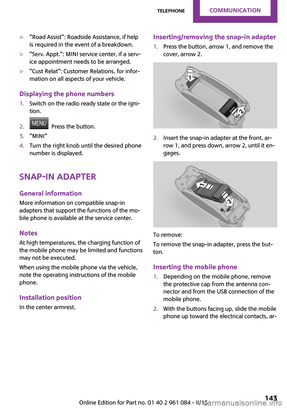
Inserting/removing the snap-in adapter1.Press the button, arrow 1, and remove the
cover, arrow 2.2.Insert the snap-in adapter at the front, ar‐
row 1, and press down, arrow 2, until it en‐
gages.
To remove:
To remove the snap-in adapter, press the but‐
ton.
Inserting the mobile phone
1.Depending on the mobile phone, remove
the protective cap from the antenna con‐
nector and from the USB connection of the
mobile phone.2.With the buttons facing up, slide the mobile
phone up toward the electrical contacts, ar‐Seite 143TelephoneCOMMUNICATION143
Online Edition for Part no. 01 40 2 961 084 - II/15
Page 154 of 223
Wheels and tiresVehicle equipment
This chapter describes all series equipment as
well as country-specific and special equipment
offered for this model series. Therefore, it also
describes equipment that may not be found in
your vehicle, for instance due to the selected
special equipment or the country version. This
also applies to safety-related functions and sys‐
tems.
When using the features and systems described
here, adhere to local regulations.
Tire inflation pressure
Safety information It is not merely the tires' service life, but also
driving comfort and, to a great extent, driving
safety that depend on the condition of the tires
and the maintenance of the specified tire pres‐
sure.
Checking the pressure Tires naturally lose pressure uniformly across all
four tires.
Check the tire inflation pressure regularly
Regularly check the tire inflation pressure
and correct it as needed: at least twice a month
and before a long trip. If you fail to observe this
precaution, you may be driving on tires with in‐
correct tire pressures, a condition that may not
only compromise your vehicle's driving stabil‐
ity, but also lead to tire damage and the risk of
an accident.
Do not drive with depressurized or flat tires, ex‐
cept for run-flat tires. A flat tire will seriously
impair your vehicle's handling and braking re‐
sponse. Attempts to drive on a flat tire can lead
to a loss of control over the vehicle. ◀Tires warm up during driving and the tire infla‐
tion pressure increases as the temperature
rises. The tire inflation pressure specifications
apply to cold tires or tires at ambient tempera‐
ture.
Only check the tire inflation pressure when the
tires are cold. This means after a maximum of
1.25 miles/2 km driving or when the vehicle
has been parked for at least 2 hours. When the
tires are warm, the tire inflation pressure is
higher.
After correcting the tire inflation pressure, reset
the Tire Pressure Monitor, refer to page 77
or reinitialize the Flat Tire Monitor, refer to
page 74.
Pressure specifications
The tables below provide all the correct infla‐
tion pressures for the specified tire sizes at am‐
bient temperature.
The inflation pressures apply to the tire sizes
approved and tire brands recommended by the
manufacturer of the MINI; a list of these is
available from the service center.
For correct identification of the right tire infla‐
tion pressures, observe the following:▷Tire sizes of your vehicle▷Maximum allowable driving speed
Tire inflation pressures for driving up to
100 mph or 160 km/h
For normal driving up to 100 mph/160 km/h,
adjust pressures to the respective tire inflation
pressures listed on the following pages in the
column for traveling speeds up to 100 mph/
160 km/h to achieve optimum driving comfort.
These tire inflation pressures can also be found
on the driver's side door pillar when the driver's
door is open.
Seite 152MOBILITYWheels and tires152
Online Edition for Part no. 01 40 2 961 084 - II/15
Page 159 of 223
Conform to Federal Safety Requirements
All passenger car tires must conform to
Federal Safety Requirements in addition to
these grades. ◀
Treadwear
The treadwear grade is a comparative rating based on the wear rate of the tire when tested
under controlled conditions on a specified gov‐
ernment test course. For example, a tire graded
150 would wear one and one-half (1 1/2) times
as well on the government course as a tire graded 100. The relative performance of tires
depends upon the actual conditions of their
use, however, and may depart significantly
from the norm due to variations in driving hab‐
its, service practices and differences in road
characteristics and climate.
TractionThe traction grades, from highest to lowest, are
AA, A, B, and C.
Those grades represent the tire's ability to stop
on wet pavement as measured under control‐
led conditions on specified government test
surfaces of asphalt and concrete. A tire marked
C may have poor traction performance.
The traction grade assigned to this tire is based
on straight-ahead braking traction tests, and
does not include acceleration, cornering, hy‐
droplaning, or peak traction characteristics.
Temperature
The temperature grades are A, the highest, B,
and C, representing the tire's resistance to the
generation of heat and its ability to dissipate
heat when tested under controlled conditions
on a specified indoor laboratory test wheel.
Sustained high temperature can cause the ma‐
terial of the tire to degenerate and reduce tire
life, and excessive temperature can lead to
sudden tire failure. The grade C corresponds to
a level of performance which all passenger car
tires must meet under the Federal Motor Vehi‐cle Safety Standard No. 109. Grades B and A
represent higher levels of performance on the
laboratory test wheel than the minimum re‐
quired by law.
Temperature grade for this tire
The temperature grade for this tire is es‐
tablished for a tire that is properly inflated and
not overloaded. Excessive speed, underinfla‐
tion, or excessive loading, either separately or
in combination, can cause heat buildup and
possible tire failure. ◀
RSC – Run-flat tires
The symbol identifying run-flat tires is a circle
with the letters RSC on the sidewall, refer to
page 160.
M+S
Winter and all-season tires.
These have better winter properties than
summer tires.
XL
Designation for specially reinforced tires.
Tire treadSummer tiresThe tread depth should not be less than
0.12 in/3 mm, although European legislation,
for example, requires a minimum tread depth
of only 0.063 in/1.6 mm. At tread depths less
than 0.12 in/3 mm, there is a great danger of
hydroplaning even in low water depths and at
raised speeds.
Winter tires
The suitability of winter tires for winter driving
is reduced noticeably when their tread depth
becomes less than 0.16 in/4 mm.Seite 157Wheels and tiresMOBILITY157
Online Edition for Part no. 01 40 2 961 084 - II/15
Page 160 of 223
Minimum tread depth
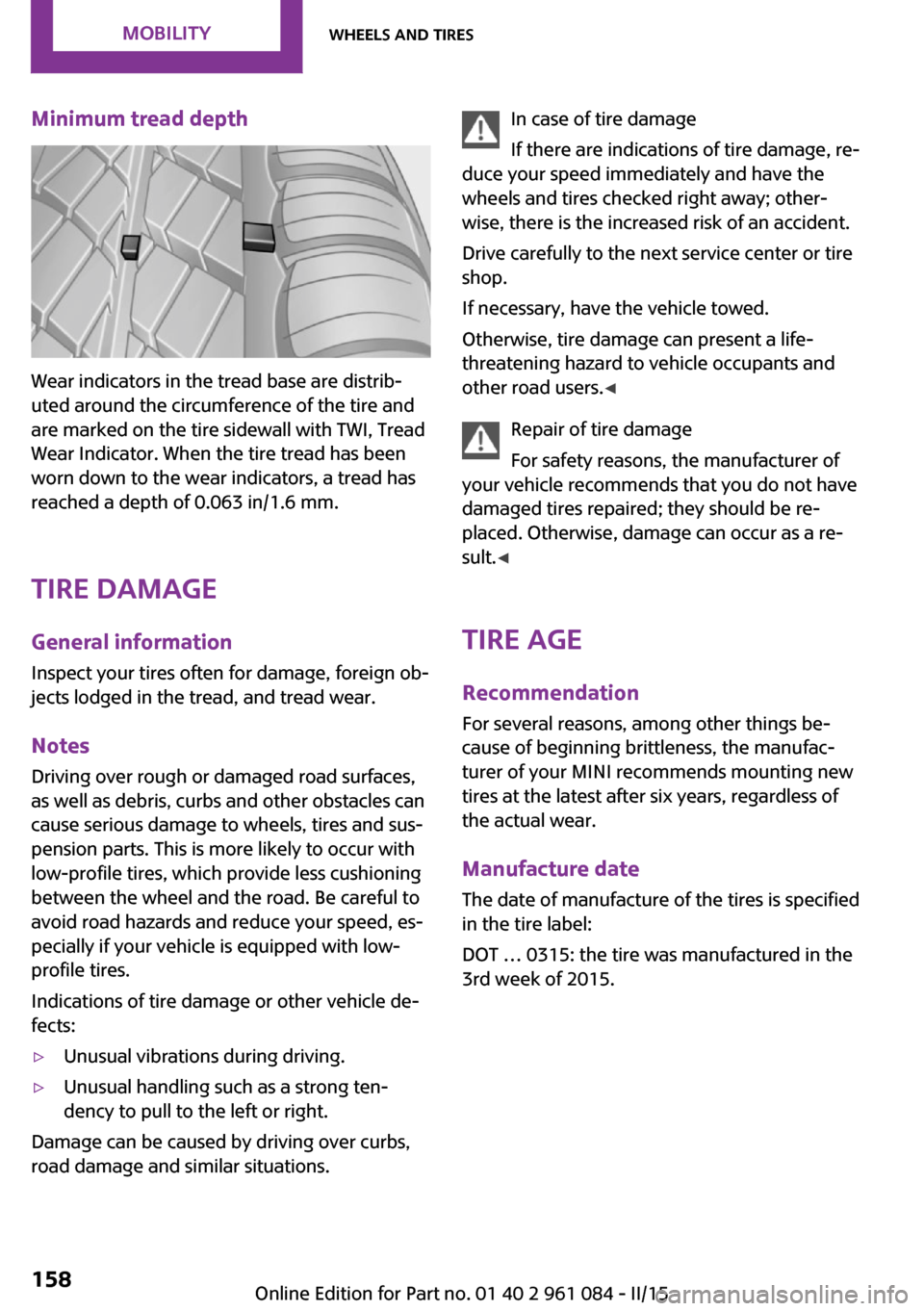
Wear indicators in the tread base are distrib‐
uted around the circumference of the tire and
are marked on the tire sidewall with TWI, Tread
Wear Indicator. When the tire tread has been
worn down to the wear indicators, a tread has
reached a depth of 0.063 in/1.6 mm.
Tire damage
General information Inspect your tires often for damage, foreign ob‐
jects lodged in the tread, and tread wear.
Notes
Driving over rough or damaged road surfaces,
as well as debris, curbs and other obstacles can
cause serious damage to wheels, tires and sus‐
pension parts. This is more likely to occur with
low-profile tires, which provide less cushioning
between the wheel and the road. Be careful to
avoid road hazards and reduce your speed, es‐
pecially if your vehicle is equipped with low-
profile tires.
Indications of tire damage or other vehicle de‐
fects:
▷Unusual vibrations during driving.▷Unusual handling such as a strong ten‐
dency to pull to the left or right.
Damage can be caused by driving over curbs,
road damage and similar situations.
In case of tire damage
If there are indications of tire damage, re‐
duce your speed immediately and have the
wheels and tires checked right away; other‐
wise, there is the increased risk of an accident.
Drive carefully to the next service center or tire
shop.
If necessary, have the vehicle towed.
Otherwise, tire damage can present a life-
threatening hazard to vehicle occupants and
other road users. ◀
Repair of tire damage
For safety reasons, the manufacturer of
your vehicle recommends that you do not have
damaged tires repaired; they should be re‐
placed. Otherwise, damage can occur as a re‐
sult. ◀
Tire age RecommendationFor several reasons, among other things be‐
cause of beginning brittleness, the manufac‐
turer of your MINI recommends mounting new
tires at the latest after six years, regardless of
the actual wear.
Manufacture date The date of manufacture of the tires is specified
in the tire label:
DOT … 0315: the tire was manufactured in the
3rd week of 2015.Seite 158MOBILITYWheels and tires158
Online Edition for Part no. 01 40 2 961 084 - II/15