ignition MINI Paceman 2015 Owner's Guide
[x] Cancel search | Manufacturer: MINI, Model Year: 2015, Model line: Paceman, Model: MINI Paceman 2015Pages: 223, PDF Size: 5.51 MB
Page 59 of 223
The vehicle only shifts up or down at appropri‐
ate engine and road speeds, e.g., it does not
shift down if the engine speed is too high. The
selected gear is briefly displayed in the instru‐
ment panel, followed by the current gear.
Shifting gears using the shift paddleson the steering wheel
The shift paddles on the steering wheel allow
you to shift gears quickly while keeping both hands on the steering wheel.▷When the shift paddles on the steering
wheel are used to shift gears while in auto‐
matic mode, the transmission switches to
manual mode.▷If the shift paddles are not used to acceler‐
ate or shift gears for a certain amount of
time, the transmission switches back to au‐
tomatic mode.
If the selector lever is in the M/S gear plane,
manual mode remains active.
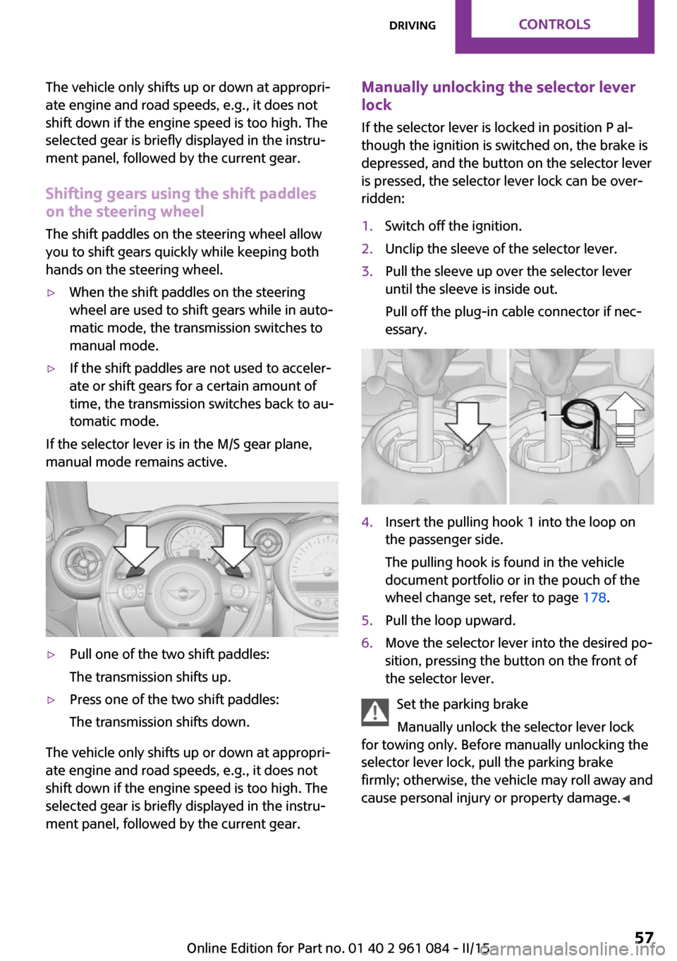
▷Pull one of the two shift paddles:
The transmission shifts up.▷Press one of the two shift paddles:
The transmission shifts down.
The vehicle only shifts up or down at appropri‐
ate engine and road speeds, e.g., it does not
shift down if the engine speed is too high. The
selected gear is briefly displayed in the instru‐
ment panel, followed by the current gear.
Manually unlocking the selector lever
lock
If the selector lever is locked in position P al‐
though the ignition is switched on, the brake is
depressed, and the button on the selector lever
is pressed, the selector lever lock can be over‐
ridden:1.Switch off the ignition.2.Unclip the sleeve of the selector lever.3.Pull the sleeve up over the selector lever
until the sleeve is inside out.
Pull off the plug-in cable connector if nec‐
essary.4.Insert the pulling hook 1 into the loop on
the passenger side.
The pulling hook is found in the vehicle
document portfolio or in the pouch of the
wheel change set, refer to page 178.5.Pull the loop upward.6.Move the selector lever into the desired po‐
sition, pressing the button on the front of
the selector lever.
Set the parking brake
Manually unlock the selector lever lock
for towing only. Before manually unlocking the
selector lever lock, pull the parking brake
firmly; otherwise, the vehicle may roll away and
cause personal injury or property damage. ◀
Seite 57DrivingCONTROLS57
Online Edition for Part no. 01 40 2 961 084 - II/15
Page 62 of 223
Information in detail
Range
Displays the estimated cruising range available
with the remaining fuel.
It is calculated based on your driving style over
the last 18 miles/30 km.
Average fuel consumption This is calculated for the period during which
the engine is running.
To reset the average consumption: press the
button on the turn indicator lever for ap‐
prox. 2 seconds.
Current fuel consumption Displays the current fuel consumption. You can
check whether you are currently driving in an
efficient and environmentally-friendly manner.
Average speed Periods in which the vehicle was parked and
the engine was switched off manually are not
included in the average speed calculations.
To reset the average speed: press the button
on the turn indicator lever for approx. 2 sec‐
onds.
Radio MINI Boost CD: displays on the
radio
Some computer functions can also be shown
on the radio display, refer to page 125.
Settings and information Operating conceptSome settings and information can only be cre‐
ated or opened while the ignition is switched
on, the vehicle is standing, and the doors are
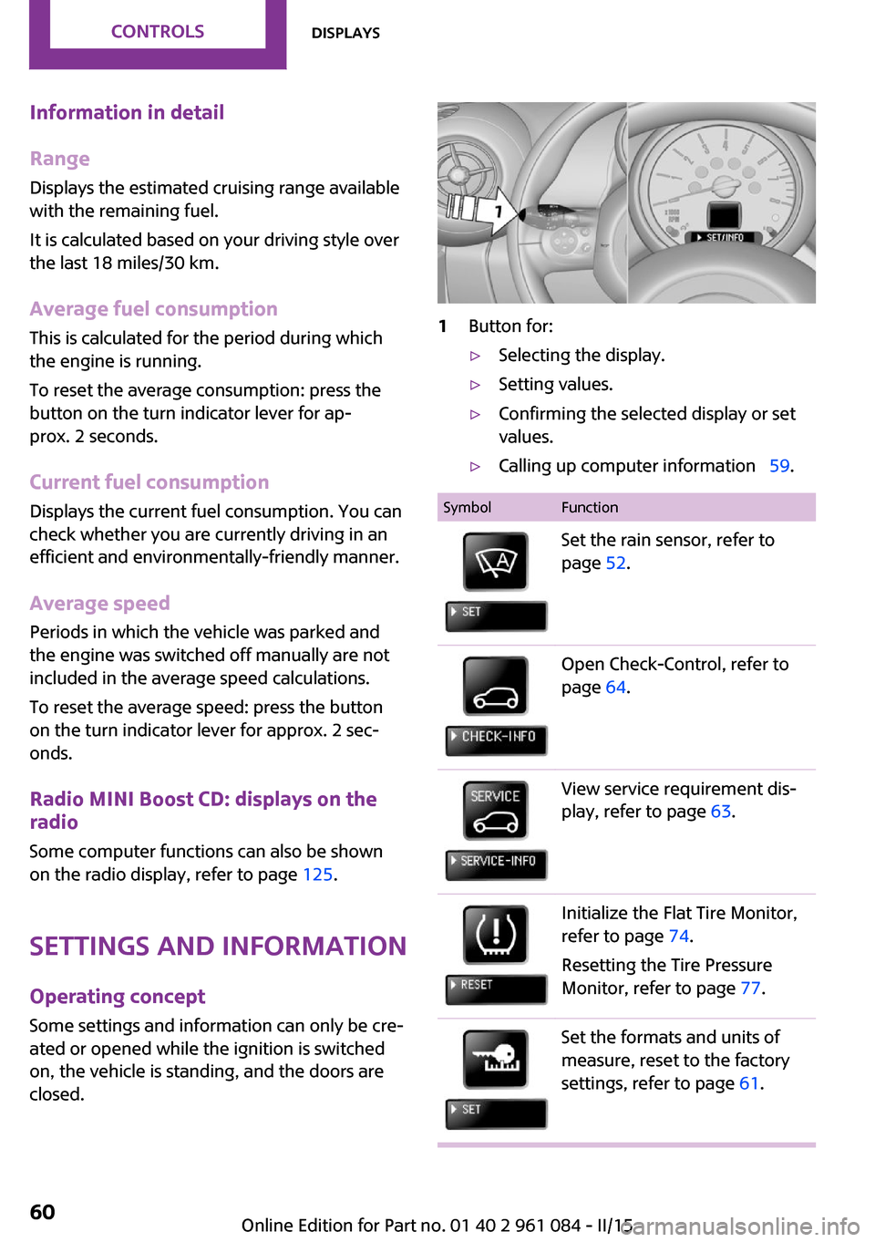
closed.1Button for:▷Selecting the display.▷Setting values.▷Confirming the selected display or set
values.▷Calling up computer information 59.SymbolFunctionSet the rain sensor, refer to
page 52.Open Check-Control, refer to
page 64.View service requirement dis‐
play, refer to page 63.Initialize the Flat Tire Monitor,
refer to page 74.
Resetting the Tire Pressure
Monitor, refer to page 77.Set the formats and units of
measure, reset to the factory
settings, refer to page 61.Seite 60CONTROLSDisplays60
Online Edition for Part no. 01 40 2 961 084 - II/15
Page 63 of 223
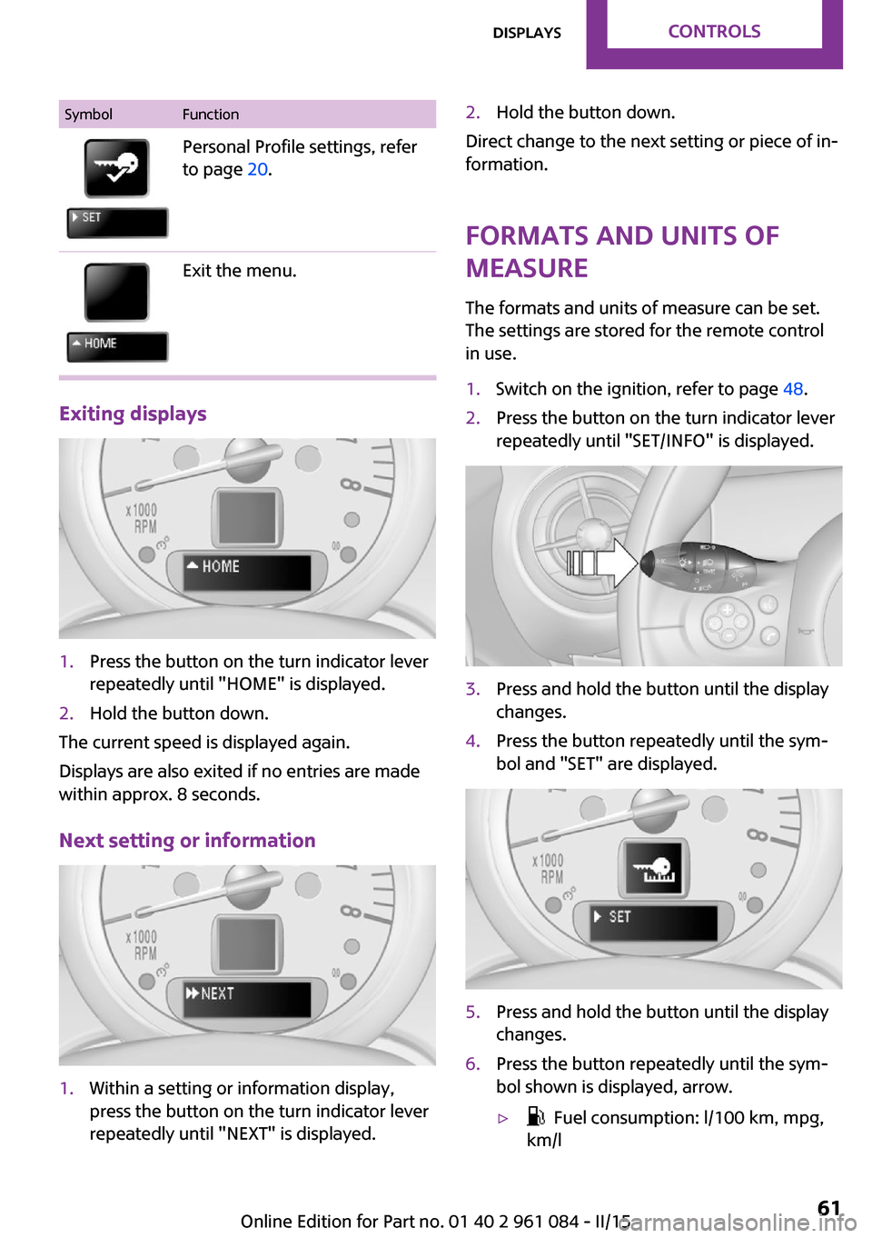
SymbolFunctionPersonal Profile settings, refer
to page 20.Exit the menu.
Exiting displays
1.Press the button on the turn indicator lever
repeatedly until "HOME" is displayed.2.Hold the button down.
The current speed is displayed again.
Displays are also exited if no entries are made
within approx. 8 seconds.
Next setting or information
1.Within a setting or information display,
press the button on the turn indicator lever
repeatedly until "NEXT" is displayed.2.Hold the button down.
Direct change to the next setting or piece of in‐
formation.
Formats and units of
measure
The formats and units of measure can be set.
The settings are stored for the remote control
in use.
1.Switch on the ignition, refer to page 48.2.Press the button on the turn indicator lever
repeatedly until "SET/INFO" is displayed.3.Press and hold the button until the display
changes.4.Press the button repeatedly until the sym‐
bol and "SET" are displayed.5.Press and hold the button until the display
changes.6.Press the button repeatedly until the sym‐
bol shown is displayed, arrow.▷ Fuel consumption: l/100 km, mpg,
km/lSeite 61DisplaysCONTROLS61
Online Edition for Part no. 01 40 2 961 084 - II/15
Page 65 of 223
Service requirements
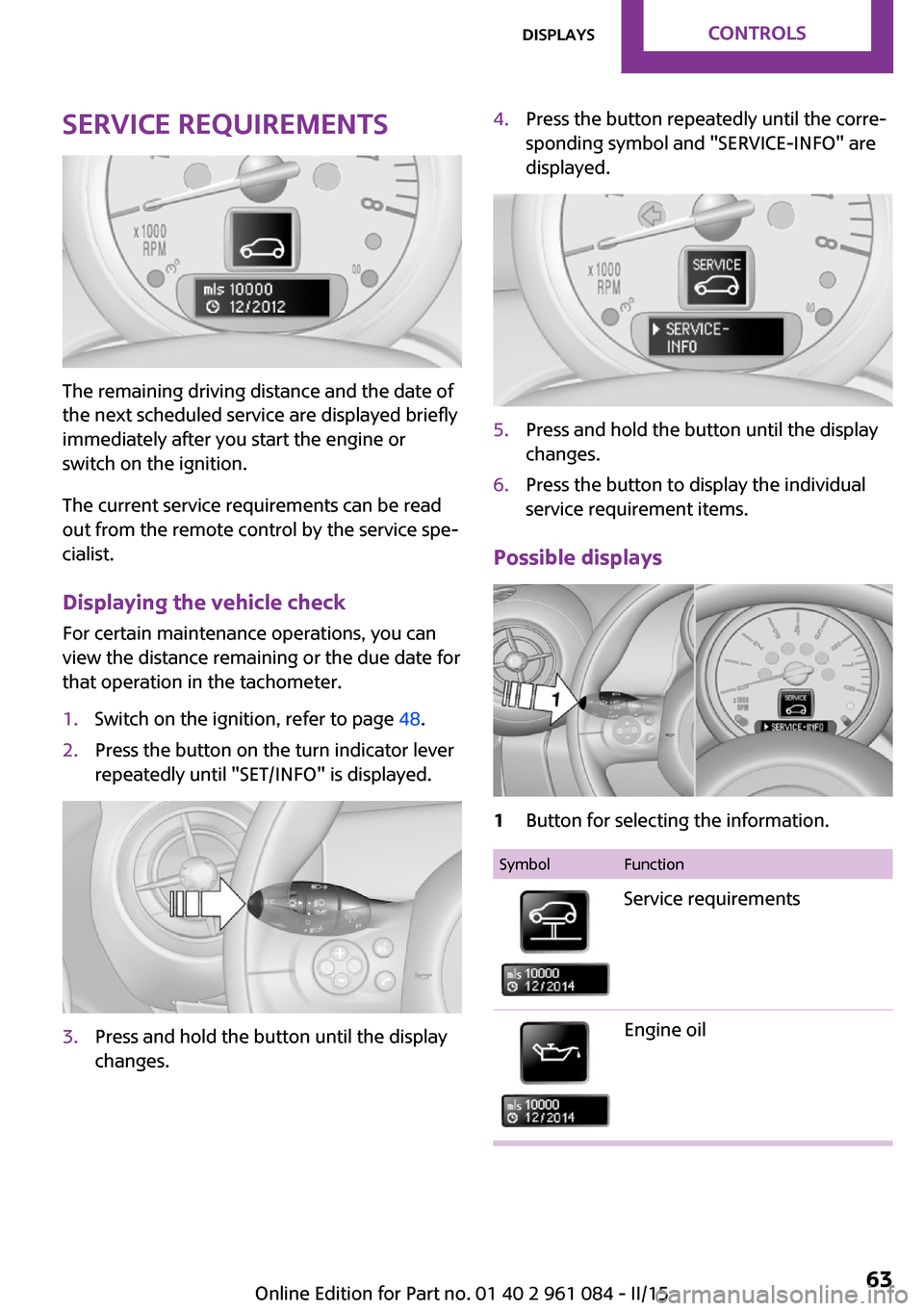
The remaining driving distance and the date of
the next scheduled service are displayed briefly
immediately after you start the engine or
switch on the ignition.
The current service requirements can be read
out from the remote control by the service spe‐
cialist.
Displaying the vehicle check
For certain maintenance operations, you can
view the distance remaining or the due date for
that operation in the tachometer.
1.Switch on the ignition, refer to page 48.2.Press the button on the turn indicator lever
repeatedly until "SET/INFO" is displayed.3.Press and hold the button until the display
changes.4.Press the button repeatedly until the corre‐
sponding symbol and "SERVICE-INFO" are
displayed.5.Press and hold the button until the display
changes.6.Press the button to display the individual
service requirement items.
Possible displays
1Button for selecting the information.SymbolFunctionService requirementsEngine oilSeite 63DisplaysCONTROLS63
Online Edition for Part no. 01 40 2 961 084 - II/15
Page 66 of 223
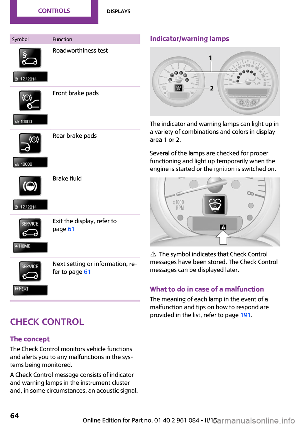
SymbolFunctionRoadworthiness testFront brake padsRear brake padsBrake fluidExit the display, refer to
page 61Next setting or information, re‐
fer to page 61
Check Control
The concept
The Check Control monitors vehicle functions
and alerts you to any malfunctions in the sys‐
tems being monitored.
A Check Control message consists of indicator
and warning lamps in the instrument cluster
and, in some circumstances, an acoustic signal.
Indicator/warning lamps
The indicator and warning lamps can light up in
a variety of combinations and colors in display
area 1 or 2.
Several of the lamps are checked for proper
functioning and light up temporarily when the
engine is started or the ignition is switched on.
The symbol indicates that Check Control
messages have been stored. The Check Control
messages can be displayed later.
What to do in case of a malfunction
The meaning of each lamp in the event of a
malfunction and tips on how to respond are
provided in the list, refer to page 191.
Seite 64CONTROLSDisplays64
Online Edition for Part no. 01 40 2 961 084 - II/15
Page 68 of 223
LampsVehicle equipmentThis chapter describes all series equipment as
well as country-specific and special equipment
offered for this model series. Therefore, it also
describes equipment that may not be found in
your vehicle, for instance due to the selected
special equipment or the country version. This
also applies to safety-related functions and sys‐
tems.
When using the features and systems described
here, adhere to local regulations.
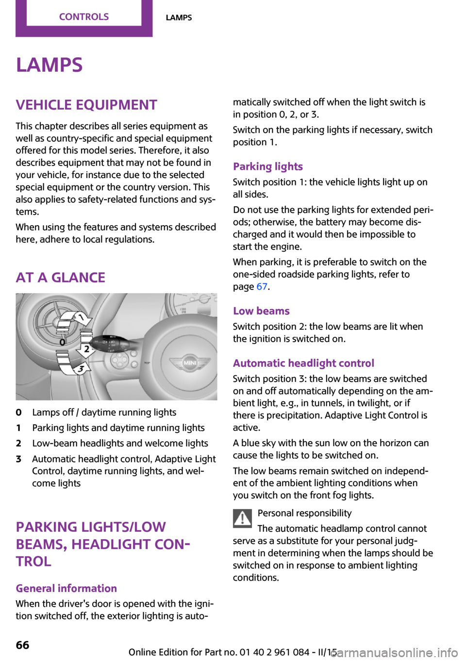
At a glance0Lamps off / daytime running lights1Parking lights and daytime running lights2Low-beam headlights and welcome lights3Automatic headlight control, Adaptive Light
Control, daytime running lights, and wel‐
come lights
Parking lights/low
beams, headlight con‐
trol
General information
When the driver's door is opened with the igni‐
tion switched off, the exterior lighting is auto‐
matically switched off when the light switch is
in position 0, 2, or 3.
Switch on the parking lights if necessary, switch
position 1.
Parking lights
Switch position 1: the vehicle lights light up on
all sides.
Do not use the parking lights for extended peri‐
ods; otherwise, the battery may become dis‐
charged and it would then be impossible to
start the engine.
When parking, it is preferable to switch on the
one-sided roadside parking lights, refer to
page 67.
Low beams Switch position 2: the low beams are lit when
the ignition is switched on.
Automatic headlight control
Switch position 3: the low beams are switched
on and off automatically depending on the am‐
bient light, e.g., in tunnels, in twilight, or if
there is precipitation. Adaptive Light Control is
active.
A blue sky with the sun low on the horizon can
cause the lights to be switched on.
The low beams remain switched on independ‐
ent of the ambient lighting conditions when
you switch on the front fog lights.
Personal responsibility
The automatic headlamp control cannot
serve as a substitute for your personal judg‐
ment in determining when the lamps should be
switched on in response to ambient lighting
conditions.Seite 66CONTROLSLamps66
Online Edition for Part no. 01 40 2 961 084 - II/15
Page 69 of 223
For example, the sensors are unable to detect
fog or hazy weather. To avoid safety risks, you
should always switch on the lamps manually
under these conditions. ◀
The exterior lighting goes out automatically af‐
ter the vehicle is switched off.
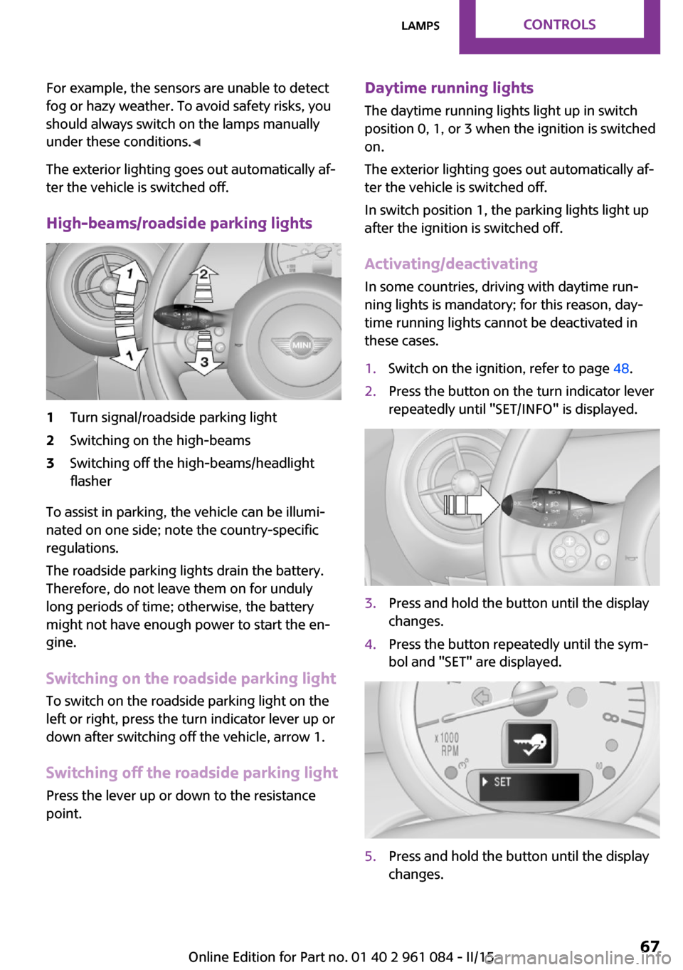
High-beams/roadside parking lights1Turn signal/roadside parking light2Switching on the high-beams3Switching off the high-beams/headlight
flasher
To assist in parking, the vehicle can be illumi‐
nated on one side; note the country-specific
regulations.
The roadside parking lights drain the battery.
Therefore, do not leave them on for unduly
long periods of time; otherwise, the battery
might not have enough power to start the en‐
gine.
Switching on the roadside parking light
To switch on the roadside parking light on the
left or right, press the turn indicator lever up or
down after switching off the vehicle, arrow 1.
Switching off the roadside parking light
Press the lever up or down to the resistance
point.
Daytime running lights
The daytime running lights light up in switch
position 0, 1, or 3 when the ignition is switched
on.
The exterior lighting goes out automatically af‐
ter the vehicle is switched off.
In switch position 1, the parking lights light up
after the ignition is switched off.
Activating/deactivating
In some countries, driving with daytime run‐
ning lights is mandatory; for this reason, day‐
time running lights cannot be deactivated in
these cases.1.Switch on the ignition, refer to page 48.2.Press the button on the turn indicator lever
repeatedly until "SET/INFO" is displayed.3.Press and hold the button until the display
changes.4.Press the button repeatedly until the sym‐
bol and "SET" are displayed.5.Press and hold the button until the display
changes.Seite 67LampsCONTROLS67
Online Edition for Part no. 01 40 2 961 084 - II/15
Page 70 of 223
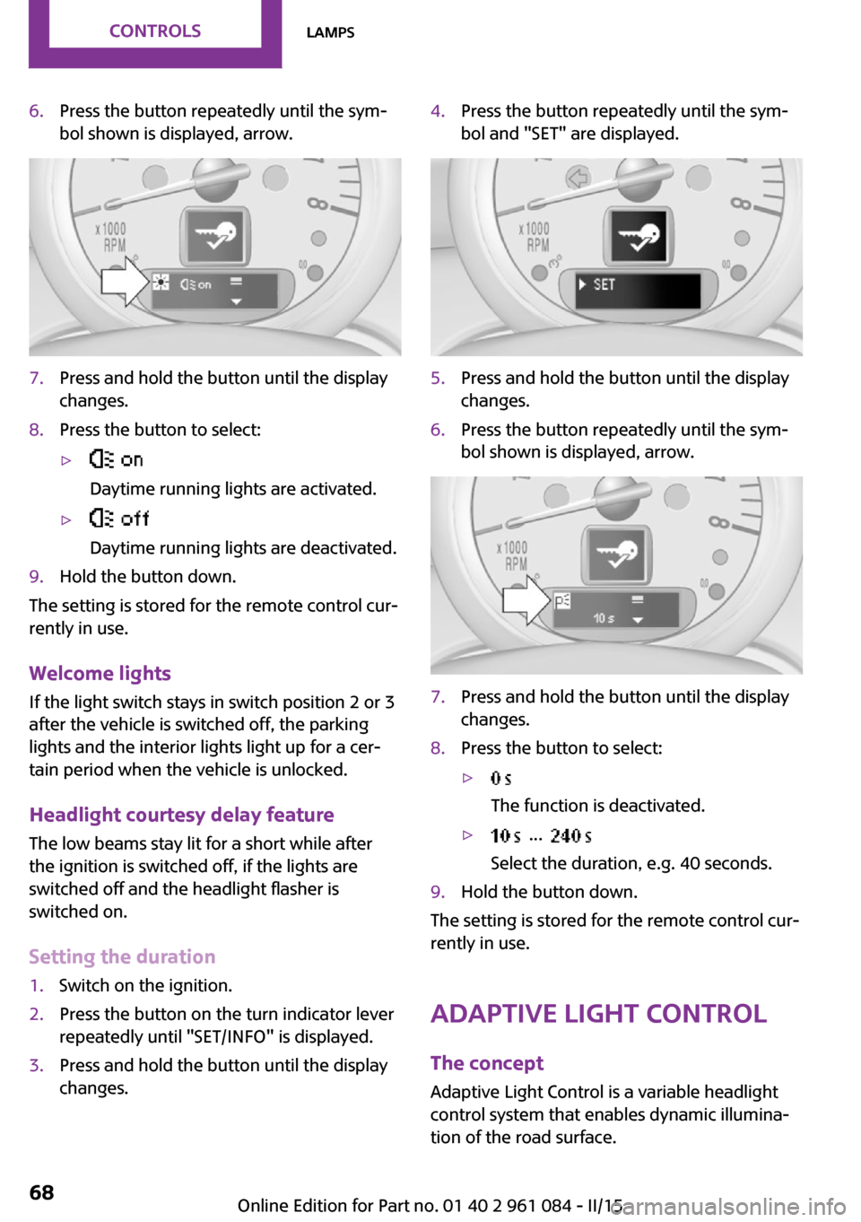
6.Press the button repeatedly until the sym‐
bol shown is displayed, arrow.7.Press and hold the button until the display
changes.8.Press the button to select:▷
Daytime running lights are activated.▷
Daytime running lights are deactivated.9.Hold the button down.
The setting is stored for the remote control cur‐
rently in use.
Welcome lights If the light switch stays in switch position 2 or 3
after the vehicle is switched off, the parking
lights and the interior lights light up for a cer‐
tain period when the vehicle is unlocked.
Headlight courtesy delay feature The low beams stay lit for a short while after
the ignition is switched off, if the lights are
switched off and the headlight flasher is
switched on.
Setting the duration
1.Switch on the ignition.2.Press the button on the turn indicator lever
repeatedly until "SET/INFO" is displayed.3.Press and hold the button until the display
changes.4.Press the button repeatedly until the sym‐
bol and "SET" are displayed.5.Press and hold the button until the display
changes.6.Press the button repeatedly until the sym‐
bol shown is displayed, arrow.7.Press and hold the button until the display
changes.8.Press the button to select:▷
The function is deactivated.▷ ...
Select the duration, e.g. 40 seconds.9.Hold the button down.
The setting is stored for the remote control cur‐
rently in use.
Adaptive Light Control
The concept
Adaptive Light Control is a variable headlight
control system that enables dynamic illumina‐
tion of the road surface.
Seite 68CONTROLSLamps68
Online Edition for Part no. 01 40 2 961 084 - II/15
Page 71 of 223

Depending on the steering angle and other pa‐
rameters, the light from the headlight follows
the course of the road.
Activating With the ignition switch on, turn the light switch
to position 3, refer to page 66.
To avoid blinding oncoming traffic, the Adap‐
tive Light Control does not swivel to the driver's
side when the vehicle is at a standstill.
When driving in reverse, Adaptive Light Control
is not active.
Malfunction The warning light lights up. Adaptive
Light Control is malfunctioning or has
failed. Have the system checked as
soon as possible.
More information, refer to page 191.
Fog lights
At a glance
To switch on the front fog lights: press the
switch.
To switch off, press the respective switch up‐
ward or downward again.
Fog lights The parking lights or low beams must be
switched on. The green indicator lamp lights up
when the front fog lights are switched on.
Depending on the vehicle equipment, the front
fog lights are switched off when the headlight
flasher or the high-beams are activated.
If the automatic headlight control is activated,
refer to page 66, the low beams are switched
on automatically when the front fog lights are
switched on.
Instrument lighting
The parking lights or low beams must be
switched on to adjust the brightness. The
brightness is increased to a certain limit and is then reduced again.▷Press the button briefly: the brightness
changes in stages.▷Press and hold the button: the brightness
changes continuously.
Interior lights
The interior lights, the footwell lights and thecargo area light are controlled automatically.
To avoid draining the battery, all lights inside
the vehicle are switched off some time after the
ignition is switched off.
Seite 69LampsCONTROLS69
Online Edition for Part no. 01 40 2 961 084 - II/15
Page 74 of 223
Protective action
Airbags are not triggered in every impact situa‐
tion, e.g., in less severe accidents or rear-end
collisions.
Information on how to ensure the opti‐
mal protective effect of the airbags▷Keep at a distance from the airbags.▷Always grasp the steering wheel on the
steering wheel rim, holding your hands at
the 3 o'clock and 9 o'clock positions, to
keep the danger of injury to your hands or
arms as low as possible if the airbag is trig‐
gered.▷There should be no people, animals, or ob‐
jects between an airbag and a person.▷Do not use the cover of the front airbag on
the front passenger side as a storage area.▷Keep the dashboard and window on the
front passenger side clear, i.e., do not cover
with adhesive labels or coverings, and do
not attach holders or cables such as for
navigation instruments and mobile phones.▷Make sure that the front passenger is sitting
correctly, i.e., keeps his or her feet and legs
in the footwell; otherwise, leg injuries can
occur if the front airbag is triggered.▷Do not place slip covers, seat cushions or
other objects on the front passenger seat
that are not approved specifically for seats
with integrated side airbags.▷Do not hang pieces of clothing, such as
jackets, over the backrests.▷Make sure that occupants keep their heads
away from the side airbag and do not rest
against the head airbag; otherwise, injuries
can occur if the airbags are triggered.▷Do not remove the airbag restraint system.▷Do not remove the steering wheel.▷Do not apply adhesive materials to the air‐
bag cover panels, cover them or modify
them in any way.▷Never modify either the individual compo‐
nents or the wiring in the airbag system.
This also applies to steering wheel covers,
the dashboard, the seats, the roof pillars
and the sides of the headliner. ◀
Even when all instructions are followed closely,
injury from contact with the airbags cannot be
ruled out in certain situations.
The ignition and inflation noise may lead to
short-term and, in most cases, temporary hear‐
ing impairment in sensitive individuals.
In the case of a malfunction, deactivation
and after triggering of the airbags
Do not touch the individual components imme‐
diately after the system has been triggered;
otherwise, there is the danger of burns.
Only have the airbags checked, repaired or dis‐
mantled and the airbag generator scrapped by
your service center or a workshop that has the
necessary authorization for handling explo‐
sives.
Non-professional attempts to service the sys‐
tem could lead to failure in an emergency or
undesired triggering of the airbag, either of
which could result in injury. ◀
Warning notices and information about the air‐
bags can also be found on the sun visors.
Automatic deactivation of the front
passenger airbags
The system determines whether the front pas‐
senger seat is occupied by measuring the elec‐
trical resistance of the human body.
The front, side, and knee airbags on the front
passenger side are activated or deactivated ac‐
cordingly by the system.
The indicator lamp above the interior rearview
mirror, refer to page 73, shows the current
status of the front passenger airbags, deacti‐
vated or activated.
Seite 72CONTROLSSafety72
Online Edition for Part no. 01 40 2 961 084 - II/15