turn signal MINI Paceman 2016 (Mini Connected) User Guide
[x] Cancel search | Manufacturer: MINI, Model Year: 2016, Model line: Paceman, Model: MINI Paceman 2016Pages: 223, PDF Size: 5.52 MB
Page 129 of 223

Switching the program type display
on/off1."SET"2."PTY"
HD Radio™ reception
Many stations broadcast both analog and digi‐
tal signals. These stations can be received digi‐
tally and therefore with better sound quality. A
digital radio network must be available to be
able to receive digital stations.
License conditions
HD Radio Technology manufactured under li‐
cense from iBiquity Digital Corporation. U.S.
and Foreign Patents. HD Radio™ and the HD,
HD Radio, and Arc logos are proprietary trade‐
marks of iBiquity Digital Corp.
Activating/deactivating digital radio
reception
1. Press the button.2."TUNER"3."SET"4."HD"
Displays
▷"HD": a station is received digitally.▷"(HD)": a station broadcasts digital signals
but digital radio reception is switched off.
In areas in which the selected station is not
continuously received in digital mode, playback
switches between analog and digital reception.
In this case, switch off digital radio reception.
Selecting the programs of a digital
station
Some stations broadcast multiple programs. To
select one of these programs:
1. Press the button repeatedly
until the desired digital station is displayed.
If a station broadcasts multiple programs,the following display appears, for example:
"HD1"2."LIST"3."HD1" ... "HD8" Select the desired pro‐
gram. Up to eight programs can be se‐
lected per station.
Displaying additional information
For digital stations, additional information can
be displayed on the current track, such as the
name of the artist.
"INFO"
Operational displays
▷"acquiring": the system is looking for digital
stations.▷"No Signal": no digital stations are being re‐
ceived.
Satellite radio
Over 100 different channels with high fidelity
can be received. The channels are offered in
fixed packages and must be activated.
You may experience signal drops and muting
events related to this new technology.
Activating or deactivated channels
1. Press the button.2."SAT"3."CAT"4.Select the desired category.
The channels are displayed.
This symbol identifies the current chan‐
nel.
Activating
1.Turn the right knob to select a channel that
is not yet activated.2.Press the right knob to confirm a channel.Seite 129Radio MINI Boost CDENTERTAINMENT129
Online Edition for Part no. 01 40 2 964 433 - VI/15
Page 139 of 223

4▷Turn: highlight the menu item on the
display or set the value.▷Press: select the highlighted menu item
or store the setting.5Open the main menu.6On/off, volume control.
Menu navigation
Selecting menu items
There are two ways to select a menu item on
the display.
Using the right knob
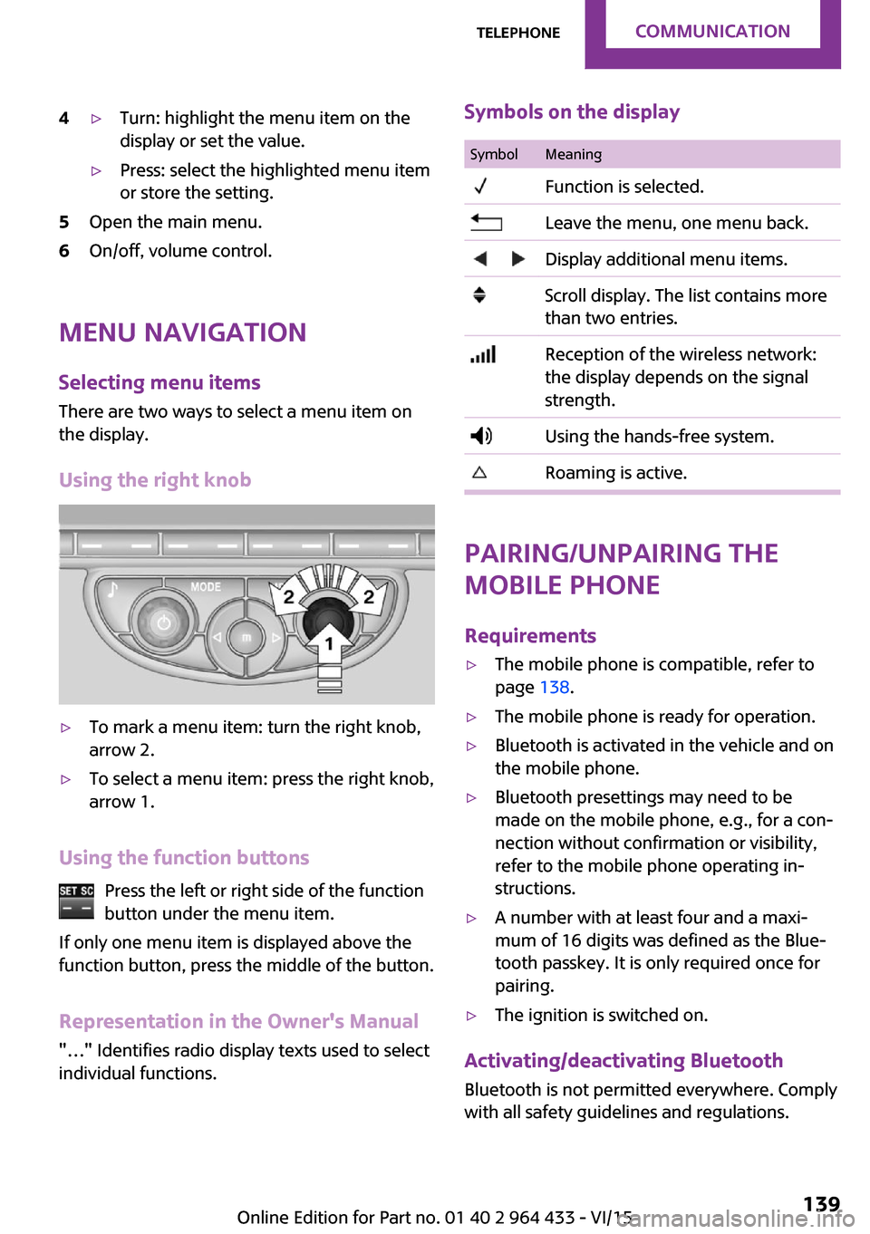
▷To mark a menu item: turn the right knob,
arrow 2.▷To select a menu item: press the right knob,
arrow 1.
Using the function buttons
Press the left or right side of the functionbutton under the menu item.
If only one menu item is displayed above the
function button, press the middle of the button.
Representation in the Owner's Manual
"…" Identifies radio display texts used to select
individual functions.
Symbols on the displaySymbolMeaning Function is selected. Leave the menu, one menu back. Display additional menu items. Scroll display. The list contains more
than two entries. Reception of the wireless network:
the display depends on the signal
strength. Using the hands-free system. Roaming is active.
Pairing/unpairing the
mobile phone
Requirements
▷The mobile phone is compatible, refer to
page 138.▷The mobile phone is ready for operation.▷Bluetooth is activated in the vehicle and on
the mobile phone.▷Bluetooth presettings may need to be
made on the mobile phone, e.g., for a con‐
nection without confirmation or visibility,
refer to the mobile phone operating in‐
structions.▷A number with at least four and a maxi‐
mum of 16 digits was defined as the Blue‐
tooth passkey. It is only required once for
pairing.▷The ignition is switched on.
Activating/deactivating Bluetooth
Bluetooth is not permitted everywhere. Comply
with all safety guidelines and regulations.
Seite 139TelephoneCOMMUNICATION139
Online Edition for Part no. 01 40 2 964 433 - VI/15
Page 141 of 223

Connecting a particular mobile phone1.Switch on the radio ready state or the igni‐
tion.2. Press the button.3."PHONE"4."BT"5.Turn the right knob until the mobile phone
to be connected is displayed.6."PRIO"
Press the button repeatedly until the de‐
sired position is reached.
Unpairing the mobile phone
1.Switch on the radio ready state or the igni‐
tion.2. Press the button.3."PHONE"4."BT"5.Turn the right knob until the mobile phone
to be unpaired is displayed.6."DELETE"7."YES"
What to do if...
Information on compatible mobile phones, re‐
fer to page 138.
The mobile phone could not be paired or con‐
nected.
▷Is Bluetooth activated in the vehicle and on
the mobile phone? Activate Bluetooth on
the vehicle and on the mobile phone.▷Do the Bluetooth passkeys on the mobile
phone and the vehicle match? Enter the
same passkey on the mobile phone and on
the radio.▷Did it take longer than 30 seconds to enter
the passkey? Repeat the pairing procedure.▷Are too many Bluetooth devices connected
to the mobile phone or vehicle? Delete con‐
nections with other devices if necessary.▷Is the mobile phone in power-save mode or
does it have only a limited remaining bat‐
tery life? Charge the mobile phone in the
snap-in adapter or via the charging cable.▷Depending on the mobile phone, it is possi‐
ble that only one mobile phone can be con‐
nected to the vehicle. Unpair the connected
mobile phone from the vehicle and pair
and connect only one mobile phone.
The mobile phone no longer reacts?
▷Switch the mobile phone off and on again.▷Is the ambient temperature too high or
low? Do not expose the mobile phone to
extreme environmental conditions.
No phone book entries or only some phone
book entries are displayed, or they are incom‐
plete.
▷Transmission of the phone book entries is
not yet complete.▷It is possible that only the phone book en‐
tries of the mobile phone or the SIM card
are transmitted.▷It may not be possible to display phone
book entries with special characters.▷The number of phone book entries to be
stored is too high.▷Is the data volume of the contact too large,
e. g., due to stored information such as
notes? Reduce the data volume of the con‐
tact.
The phone connection quality is poor.
▷The strength of the Bluetooth signal on the
mobile phone can be adjusted, depending
on the mobile phone.▷Insert the mobile phone into the snap-in
adapter or place it in the area of the center
console.▷Adjust the volume of the microphone and
loudspeakers.Seite 141TelephoneCOMMUNICATION141
Online Edition for Part no. 01 40 2 964 433 - VI/15
Page 176 of 223

driving cautiously with the front fog lights, pro‐
vided this is permitted by local laws.
DANGER
There can be high voltage in the lighting
system. There is danger to life. The manufac‐
turer of your vehicle recommends that the
work on the lighting system including bulb re‐
placement be performed by a dealer’s service
center or another qualified service center or re‐
pair shop. ◀
Front lights, bulb replacement
Overview
Headlights1Low beams/high-beams2Turn signal
Lower front lights
1Parking lights2Daytime running lights or fog lightsLower LED front lights1Parking lights / daytime running lights2Fog lights
Halogen low beams and high-beams
H13 bulb, 60/55 watt
Access to the bulbs through the engine
compartment
Follow the general instructions on lamps and
bulbs, refer to page 175.
Low beam/high-beam bulbs can be changed
from the engine compartment.
To remove the cover:
1.Press the tab.2.Fold away the cover and take it out of the
holder.
Proceed in reverse order to attach the cover.
Seite 176MOBILITYReplacing components176
Online Edition for Part no. 01 40 2 964 433 - VI/15
Page 177 of 223

Replacing the bulb1.Turn the bulb counterclockwise, arrow 1,
and remove it, arrow 2.2.Press the release, arrow 1, and pull off the
connector, arrow 2.3.Insert the new bulb and attach the cover in
reverse order.
LED parking lights/LED fog lights/LED
daytime running lights
Follow the general instructions on lamps and
bulbs, refer to page 175.
Lights are implemented using LED technology.
In case of a malfunction, contact a dealer’s
service center or another qualified service cen‐
ter or repair shop.
Turn signals/parking lights/roadside
parking lights/fog lights/and daytime running lights
Access to the bulbs via the wheel housing
Follow the general instructions on lamps and
bulbs, refer to page 175.
1Turn signal2Parking lights/roadside parking lights/fog
lights/and daytime running lights
Replacing the turn signal bulb
21-watt bulb, P 21 W, or PY 21 W
1.Turn the wheel.2.Remove cover 1.
To do this, turn the cover counterclockwise.3.Remove the inside cover. To do this, turn
the cover counterclockwise.4.Turn the bulb counterclockwise and re‐
move it.5.Insert the new bulb and attach the covers
in reverse order.Seite 177Replacing componentsMOBILITY177
Online Edition for Part no. 01 40 2 964 433 - VI/15
Page 178 of 223

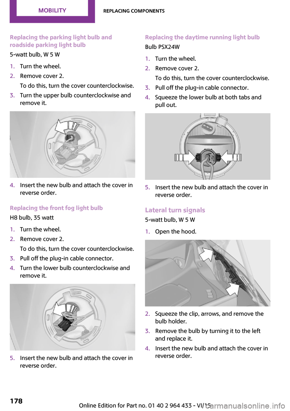
Replacing the parking light bulb and
roadside parking light bulb
5-watt bulb, W 5 W1.Turn the wheel.2.Remove cover 2.
To do this, turn the cover counterclockwise.3.Turn the upper bulb counterclockwise and
remove it.4.Insert the new bulb and attach the cover in
reverse order.
Replacing the front fog light bulb
H8 bulb, 35 watt
1.Turn the wheel.2.Remove cover 2.
To do this, turn the cover counterclockwise.3.Pull off the plug-in cable connector.4.Turn the lower bulb counterclockwise and
remove it.5.Insert the new bulb and attach the cover in
reverse order.Replacing the daytime running light bulb
Bulb PSX24W1.Turn the wheel.2.Remove cover 2.
To do this, turn the cover counterclockwise.3.Pull off the plug-in cable connector.4.Squeeze the lower bulb at both tabs and
pull out.5.Insert the new bulb and attach the cover in
reverse order.
Lateral turn signals
5-watt bulb, W 5 W
1.Open the hood.2.Squeeze the clip, arrows, and remove the
bulb holder.3.Remove the bulb by turning it to the left
and replace it.4.Insert the new bulb and attach the cover in
reverse order.Seite 178MOBILITYReplacing components178
Online Edition for Part no. 01 40 2 964 433 - VI/15
Page 179 of 223

Side marker lights
To replace these bulbs, contact a dealer’s serv‐
ice center or another qualified service center or
repair shop.
Tail lights, bulb replacement
Follow the general instructions on lamps and
bulbs, refer to page 175.
Turn signal: 21-watt bulb, PY 21 W
MINI Countryman1Brake/tail light2Turn signal3Brake/tail light4Backup light
MINI Paceman
1Brake light2Tail light3Turn signal4Backup lightReplacing
All bulbs are integrated in a central bulb holder.
MINI Countryman1.Switch off the lights and take the remote
control out of the ignition lock.2.Open the tailgate.3.Press the cover out of the cargo area side
panel at the rear and remove it.4.Detach the emergency release of the fuel
filler flap, refer to page 150, and push it
aside with the foam insert.
Ensure that the emergency release is not
damaged.5.Disengage the bulb holder by pushing
down the clip, arrow 1.6.Take out the bulb holder and detach the
cable, arrow 2.7.Apply gentle pressure to the bulb while
turning it to the left and remove it.8.Insert the new bulb and mount the bulb
holder in reverse order. Ensure that the
bulb holder engages in all fasteners.Seite 179Replacing componentsMOBILITY179
Online Edition for Part no. 01 40 2 964 433 - VI/15
Page 187 of 223

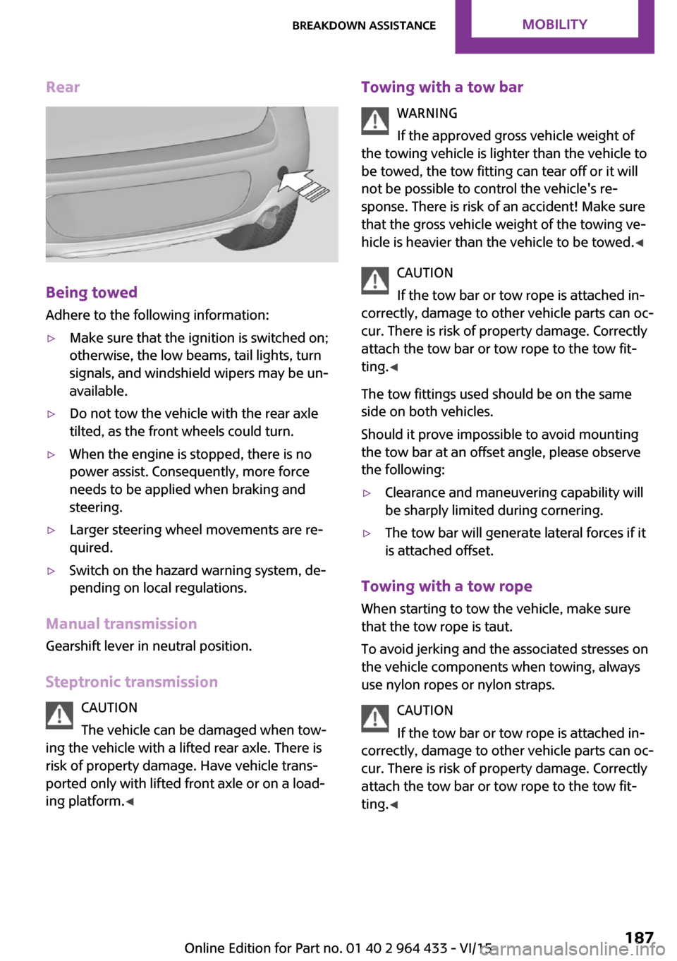
Rear
Being towed
Adhere to the following information:
▷Make sure that the ignition is switched on;
otherwise, the low beams, tail lights, turn
signals, and windshield wipers may be un‐
available.▷Do not tow the vehicle with the rear axle
tilted, as the front wheels could turn.▷When the engine is stopped, there is no
power assist. Consequently, more force
needs to be applied when braking and
steering.▷Larger steering wheel movements are re‐
quired.▷Switch on the hazard warning system, de‐
pending on local regulations.
Manual transmission
Gearshift lever in neutral position.
Steptronic transmission CAUTION
The vehicle can be damaged when tow‐
ing the vehicle with a lifted rear axle. There is
risk of property damage. Have vehicle trans‐
ported only with lifted front axle or on a load‐
ing platform. ◀
Towing with a tow bar
WARNING
If the approved gross vehicle weight of
the towing vehicle is lighter than the vehicle to
be towed, the tow fitting can tear off or it will
not be possible to control the vehicle's re‐
sponse. There is risk of an accident! Make sure
that the gross vehicle weight of the towing ve‐
hicle is heavier than the vehicle to be towed. ◀
CAUTION
If the tow bar or tow rope is attached in‐
correctly, damage to other vehicle parts can oc‐
cur. There is risk of property damage. Correctly
attach the tow bar or tow rope to the tow fit‐
ting. ◀
The tow fittings used should be on the same
side on both vehicles.
Should it prove impossible to avoid mounting
the tow bar at an offset angle, please observe
the following:▷Clearance and maneuvering capability will
be sharply limited during cornering.▷The tow bar will generate lateral forces if it
is attached offset.
Towing with a tow rope
When starting to tow the vehicle, make sure
that the tow rope is taut.
To avoid jerking and the associated stresses on
the vehicle components when towing, always
use nylon ropes or nylon straps.
CAUTION
If the tow bar or tow rope is attached in‐
correctly, damage to other vehicle parts can oc‐ cur. There is risk of property damage. Correctly
attach the tow bar or tow rope to the tow fit‐ ting. ◀
Seite 187Breakdown assistanceMOBILITY187
Online Edition for Part no. 01 40 2 964 433 - VI/15
Page 194 of 223

Indicator/warning lampsVehicle features and op‐
tions
This chapter describes all standard, country-
specific and optional features offered with the
series. It also describes features that are notnecessarily available in your car, e. g., due to
the selected options or country versions. This
also applies to safety-related functions and sys‐
tems.
When using the features and systems described
here, adhere to local regulations.
Overview
The indicator and warning lights can light up in
a variety of combinations and colors in display
area 1 or 2. The table contains information on
causes and how to respond. Note whether a
lamp lights up alone or in combination with an‐
other. Some lights can light up in different col‐
ors. Corresponding distinctions are made in the
text. 12CauseHow to respondTurn signalThe high-beams/headlight flasher are
switched on.The front fog lamps are switched on.The rear fog lights are switched on.Fasten safety belts.Fasten safety belt, refer to page 41.External temperature warningDrive conservatively, refer to
page 61.Seite 194MOBILITYIndicator/warning lamps194
Online Edition for Part no. 01 40 2 964 433 - VI/15
Page 213 of 223

Brakes, MINI maintenancesystem 172
Brakes, service require‐ ments 66
Brake system, MINI mainte‐ nance system 172
Braking, notes 113
Braking, parking brake 52
Breakdown assistance, Road‐ side Assistance 184
Breaking in 112
Buckle tongues height adjust‐ ment 39
Button for starting the engine, refer to Start/Stop button 50
C
California Proposition 65 Warning 7
Car battery, refer to Vehicle battery 182
Car care products 191
Care, displays 193
Care, vehicle 191
Cargo area, Comfort Ac‐ cess 29
Cargo area door, refer to Tail‐ gate 27
Cargo area, enlarging, cargo cover 102
Cargo area, flat loading floor 104
Cargo area light, refer to Inte‐ rior lights 72
Cargo area, multi-function hook 105
Cargo area, opening from the outside 27
Cargo area, partition net 104
Car horn, refer to Horn 12
Carpet, care 193
Car phone, refer to Tele‐ phone 138
Car wash 190 CBC, Cornering Brake Con‐
trol 84
CBS Condition Based Serv‐ ice 172
CD/DVD drives, care 193
Center armrest 107
Center console, refer to Around the center con‐
sole 15
Center rail 107
Center rail, refer to Storage compartments 107
Central locking, Comfort Ac‐ cess 28
Central locking from the in‐ side 25
Central locking system, con‐ cept 21
Central locking system, from the outside 21
Changes, technical, refer to Own Safety 6
Changing wheels/tires 160
Check Control 67
Children, transporting 45
Child restraint fixing system LATCH 47
Child restraint fixing sys‐ tems 45
Child restraint fixing systems, mounting 46
Child seat, mounting 46
Child seats, refer to Transport‐ ing children safely 45
Chrome parts, care 192
Circulation of air, refer to Re‐ circulated air mode, air con‐
ditioner 92
Circulation of air, refer to Re‐ circulated air mode, auto‐
matic climate control 94
Cleaning, displays 193
Cleaning, refer to Care 190
Climate 91
Climate mode, ventilation 95
Clock 61 Clock, 12h/24h mode 64
Closing from the inside 25
Closing from the outside 22
Clutch, breaking in 112
Cockpit 12
Cold start, refer to Starting the engine 51
Combination instrument, refer to Displays 14
Combination switch, refer to Turn signal/high-beams/
headlight flasher 53
Combination switch, refer to Washer/wiper system 54
Comfort Access 28
Comfort Access, in the car wash 29
Comfort Access, replacing the battery 30
Comfort area, refer to Around the center console 15
Compartment for remote con‐ trol, refer to Ignition lock 50
Compass, digital 98
Computer 62
Computer, displaying informa‐ tion 62
Condition Based Service CBS 172
Confirmation signals for vehi‐ cle locking/unlocking 23
Consumption, refer to Aver‐ age fuel consumption 63
Control Display, care 193
Controls and displays 12
Control systems, driving stabil‐ ity 84
Convenient operation, win‐ dow 23
Coolant temperature 62
Cooling function, switching on and off 95
Cooling, maximum 94
Cornering Brake Control, CBC 84
Corrosion on brake discs 114 Seite 213Everything from A to ZREFERENCE213
Online Edition for Part no. 01 40 2 964 433 - VI/15