air condition MINI Paceman 2016 Owner's Manual (Mini Connected)
[x] Cancel search | Manufacturer: MINI, Model Year: 2016, Model line: Paceman, Model: MINI Paceman 2016Pages: 223, PDF Size: 5.52 MB
Page 7 of 223
be necessary to adapt your vehicle to poten‐
tially differing operating conditions and permit
requirements. If your vehicle does not comply
with the homologation requirements in a cer‐
tain country you may not be able to lodge war‐
ranty claims for your vehicle there. Further in‐
formation on warranty is available from a
dealer’s service center.
Maintenance and repairs
Advanced technology, e.g., the use of modern
materials and high-performance electronics,
requires suitable maintenance and repair work.
The manufacturer of your vehicle recommends
that you entrust corresponding procedures to a
MINI dealer’s service center. If you choose to
use another service facility, the manufacturer of
your vehicle recommends use of a facility that
performs work, e.g. maintenance and repair,
according to MINI specifications with properly
trained personnel, referred to in this Owner's
Manual as "another qualified service center or
repair shop".
If work is performed improperly, e.g. mainte‐
nance and repair, there is a risk of subsequent
damage and related safety risks.
Parts and accessories The manufacturer of your vehicle recommends
the use of parts and accessory products ap‐ proved by the manufacturer of the MINI.
Approved parts and accessories, and advice on
their use and installation are available from a
MINI dealer's service center.
MINI parts and accessories were tested by the
manufacturer of the MINI for their safety and
suitability in MINI vehicles.
The manufacturer of your vehicle warrants gen‐
uine MINI parts and accessories.
The manufacturer of your vehicle does not
evaluate whether each individual product from
another manufacturer can be used with MINI
vehicles without presenting a safety hazard,
even if a country-specific official approval wasissued. The manufacturer of your vehicle does
not evaluate whether these products are suita‐
ble for MINI vehicles under all usage conditions.
California Proposition 65 Warning
California laws require us to state the following
warning:
Engine exhaust and a wide variety of automo‐
bile components and parts, including compo‐
nents found in the interior furnishings in a vehi‐
cle, contain or emit chemicals known to the
State of California to cause cancer and birth de‐
fects and reproductive harm. In addition, cer‐
tain fluids contained in vehicles and certain
products of component wear contain or emit
chemicals known to the State of California to
cause cancer and birth defects or other repro‐
ductive harm. Battery posts, terminals and re‐
lated accessories contain lead and lead com‐
pounds. Wash your hands after handling. Used
engine oil contains chemicals that have caused
cancer in laboratory animals. Always protect
your skin by washing thoroughly with soap and
water.
Service and warranty
We recommend that you read this publication
thoroughly. Your vehicle is covered by the fol‐
lowing warranties:▷New Vehicle Limited Warranty.▷Rust Perforation Limited Warranty.▷Federal Emissions System Defect Warranty.▷Federal Emissions Performance Warranty.▷California Emission Control System Limited
Warranty.
Detailed information about these warranties is
listed in the Service and Warranty Information
Booklet for US models or in the Warranty and
Service Guide Booklet for Canadian models.
Your vehicle has been specifically adapted and
designed to meet the particular operating con‐
ditions and homologation requirements in your
country and continental region in order to de‐
Seite 7Information7
Online Edition for Part no. 01 40 2 964 433 - VI/15
Page 8 of 223
liver the full driving pleasure while the vehicle is
operated under those conditions. If you wish to
operate your vehicle in another country or re‐
gion, you may be required to adapt your vehi‐
cle to meet different prevailing operating con‐
ditions and homologation requirements. You
should also be aware of any applicable war‐
ranty limitations or exclusions for such country
or region. In such case, please contact Cus‐
tomer Relations for further information.
Maintenance
Maintain the vehicle regularly to sustain the
road safety, operational reliability and the New
Vehicle Limited Warranty.
Specifications for required maintenance meas‐
ures:▷MINI Maintenance system▷Service and Warranty Information Booklet
for US models▷Warranty and Service Guide Booklet for
Canadian models
If the vehicle is not maintained according to
these specifications, this could result in serious
damage to the vehicle. Such damage is not
covered by the MINI New Vehicle Limited War‐
ranty.
Data memory
Many electronic components on your vehicle
are equipped with data memories that tempo‐
rarily or permanently store technical informa‐
tion about the condition of the vehicle, events
and faults. This technical information generally
records the state of a component, a module, a
system or the environment:
▷Operating mode of system components, fill
levels for instance.▷Status messages for the vehicle and from its
individual components, e.g., wheel rotation
speed/vehicle speed, deceleration, trans‐
verse acceleration.▷Malfunctions and malfunctions in important
system components, e.g., lights and brakes.▷Responses by the vehicle to special situa‐
tions such as airbag deployment or engag‐
ing the stability control system.▷Ambient conditions, such as temperature.
This data is purely technical in nature and is
used to detect and correct faults and to opti‐
mize vehicle functions. Motion profiles over
routes traveled cannot be created from this
data. When service offerings are used, e.g., re‐
pair services, service processes, warranty
claims, quality assurance, this technical infor‐
mation can be read out from the event and
fault memories by employees of the dealer’s
service center or another qualified service cen‐
ter or repair shop, including the manufacturer,
using special diagnostic tools. You can obtain
further information there if you need it. After
an error is corrected, the information in the
fault memory is deleted or overwritten on a
continuous basis.
With the vehicle in use there are situations
where you can associate these technical data
with individuals if combined with other infor‐
mation, e.g., an accident report, damage to the
vehicle, eye witness accounts — possibly with
the assistance of an expert.
Additional functions that are contractually
agreed with the customer - such as vehicle
emergency locating - you can transmit certain
vehicle data from the vehicle.
Event Data Recorder EDR
This vehicle is equipped with an event data re‐
corder EDR. The main purpose of an EDR is to
record, in certain crash or near crash-like situa‐
tions, such as an air bag deployment or hitting
a road obstacle, data that will assist in under‐
standing how a vehicle's systems performed.
The EDR is designed to record data related to
vehicle dynamics and safety systems for a short
period of time, typically 30 seconds or less.
Seite 8Information8
Online Edition for Part no. 01 40 2 964 433 - VI/15
Page 15 of 223
Indicator/warning lights
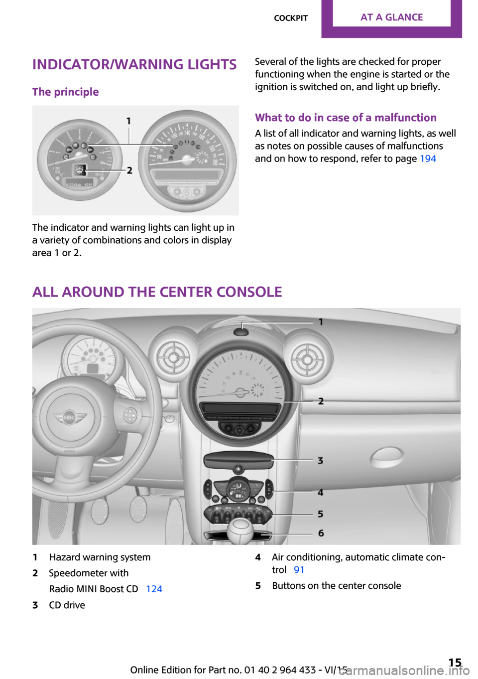
The principle
The indicator and warning lights can light up in
a variety of combinations and colors in display
area 1 or 2.
Several of the lights are checked for proper
functioning when the engine is started or the
ignition is switched on, and light up briefly.
What to do in case of a malfunction
A list of all indicator and warning lights, as well
as notes on possible causes of malfunctions
and on how to respond, refer to page 194
All around the center console
1Hazard warning system2Speedometer with
Radio MINI Boost CD 1243CD drive4Air conditioning, automatic climate con‐
trol 915Buttons on the center consoleSeite 15CockpitAT A GLANCE15
Online Edition for Part no. 01 40 2 964 433 - VI/15
Page 24 of 223
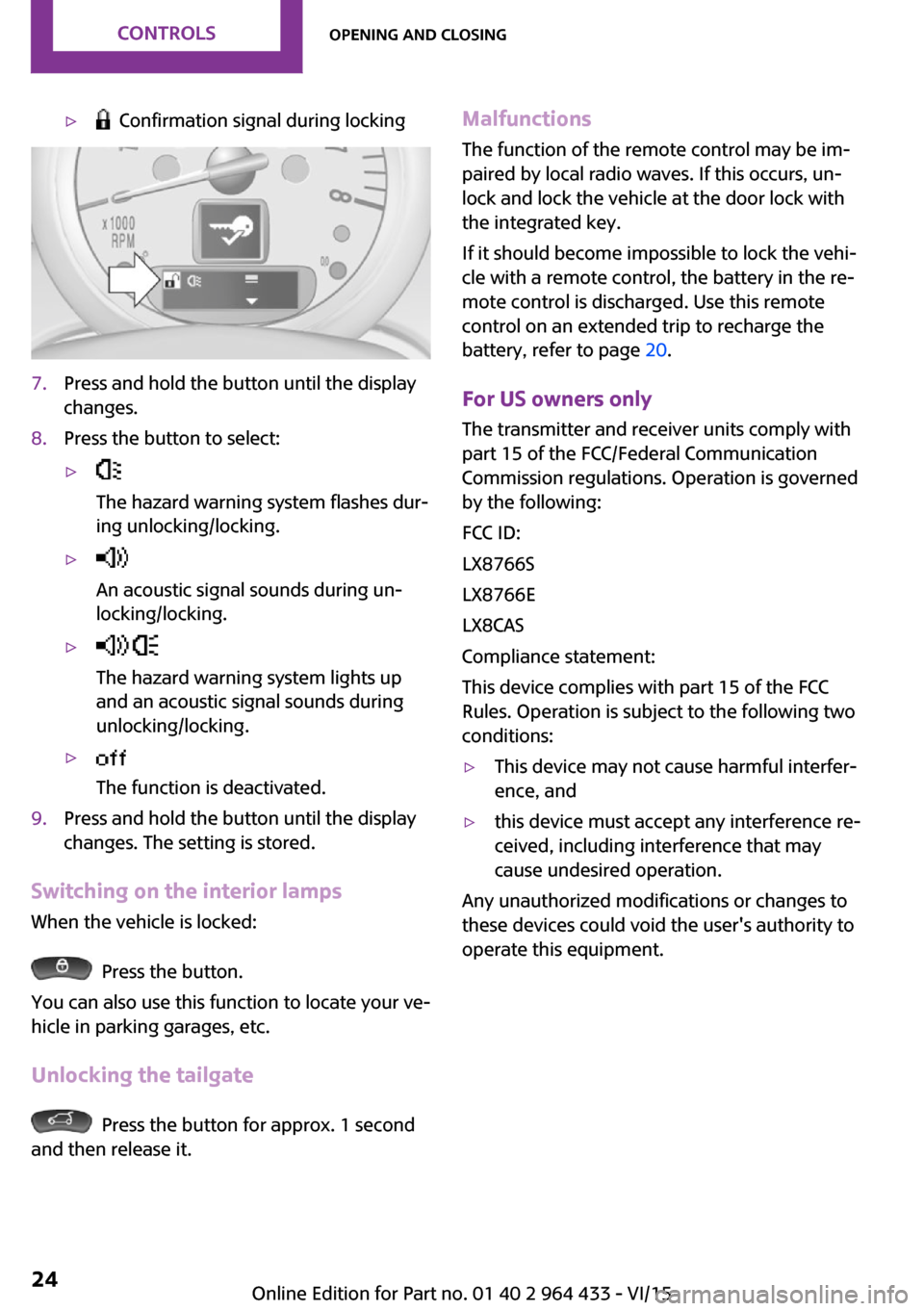
▷ Confirmation signal during locking7.Press and hold the button until the display
changes.8.Press the button to select:▷
The hazard warning system flashes dur‐
ing unlocking/locking.▷
An acoustic signal sounds during un‐
locking/locking.▷
The hazard warning system lights up
and an acoustic signal sounds during
unlocking/locking.▷
The function is deactivated.9.Press and hold the button until the display
changes. The setting is stored.
Switching on the interior lamps
When the vehicle is locked:
Press the button.
You can also use this function to locate your ve‐
hicle in parking garages, etc.
Unlocking the tailgate
Press the button for approx. 1 second
and then release it.
Malfunctions
The function of the remote control may be im‐
paired by local radio waves. If this occurs, un‐ lock and lock the vehicle at the door lock with
the integrated key.
If it should become impossible to lock the vehi‐
cle with a remote control, the battery in the re‐
mote control is discharged. Use this remote control on an extended trip to recharge the
battery, refer to page 20.
For US owners only The transmitter and receiver units comply with
part 15 of the FCC/Federal Communication
Commission regulations. Operation is governed
by the following:
FCC ID:
LX8766S
LX8766E
LX8CAS
Compliance statement:
This device complies with part 15 of the FCC
Rules. Operation is subject to the following two
conditions:▷This device may not cause harmful interfer‐
ence, and▷this device must accept any interference re‐
ceived, including interference that may
cause undesired operation.
Any unauthorized modifications or changes to
these devices could void the user's authority to
operate this equipment.
Seite 24CONTROLSOpening and closing24
Online Edition for Part no. 01 40 2 964 433 - VI/15
Page 79 of 223
center or another qualified service center or
repair shop.2.Rectify the flat tire using the Mobility Sys‐
tem, refer to page 162.
Run-flat tires
You can continue driving with a damaged tire
at speeds up to 50 mph/80 km/h.
Continued driving with a flat tire
If continuing to drive with a damaged tire:
1.Avoid sudden braking and steering maneu‐
vers.2.Do not exceed a speed of 50 mph/80 km/h.3.At the next opportunity, check the inflation
pressure in all four tires.
If the tire inflation pressure in all four tires is
correct, the Flat Tire Monitor may not have
been initialized. In this case, initialize the
system.
Possible driving distance with complete loss of
tire inflation pressure:
The possible driving distance after a loss of tire
inflation pressure depends on the cargo load
and the driving style and conditions.
For a vehicle containing an average load, the
possible driving distance is ap‐
prox. 50 miles/80 km.
When the vehicle is driven with a damaged tire,
its handling characteristics change, e.g., re‐
duced lane stability during braking, a longer
braking distance, and altered self-steering
properties. Adjust your driving style accord‐
ingly. Avoid abrupt steering maneuvers or driv‐
ing over obstacles, e. g., curbs, potholes, etc.
Because the possible driving distance depends
on how the vehicle is used during the trip, the
actual distance may be smaller or greater de‐
pending on the driving speed, road conditions,
external temperature, cargo load, etc.
WARNING
Your vehicle handles differently when a
run-flat tire is damaged and has low or missing
tire inflation pressure, e.g., your lane stability is
reduced when braking, braking distances are
longer and the self-steering properties will
change. There is risk of an accident.
Drive moderately and do not exceed a speed of
50 mph/80 km/h. ◀
Final tire failure
Vibrations or loud noises while driving can indi‐
cate the final failure of a tire. Reduce speed and
stop, otherwise, pieces of the tire could come
loose and cause an accident. Do not continue
driving. Contact a dealer’s service center or an‐
other qualified service center or repair shop.
Tire Pressure Monitor
TPM
The concept
The system monitors the tire pressure in the
four mounted tires. The system notifies you if
there is a significant loss of pressure in one or
more tires. Sensors in the tire valves measure
the tire pressure.
Information
To operate the system, also note the additional
information and instructions contained under
Tire inflation pressure, refer to page 154.
Functional requirements
The system must have been reset while the in‐
flation pressure was correct; otherwise, it may
not reliably signal a loss in pressure.
Perform a system reset after adjusting the tire
inflation pressure to a new value and after
changing a tire or wheel
Always use wheels with TPM electronics to en‐
sure that the system will operate properly.Seite 79SafetyCONTROLS79
Online Edition for Part no. 01 40 2 964 433 - VI/15
Page 81 of 223
of an accident. Do not continue driving if the
vehicle is not equipped with run-flat tires. Fol‐
low the information on run-flat tires and con‐
tinued driving with these tires. ◀
When a low inflation pressure is indicated, DSC
Dynamic Stability Control is switched on if nec‐
essary.
Actions in the event of a flat tire Normal tires1.Identify the damaged tire.
Do this by checking the air pressure in all
four tires. The tire pressure gauge of the
Mobility System, refer to page 162, can be
used for this purpose.
If the tire inflation pressure in all four tires is
correct, the Tire Pressure Monitor may not
have been reset. Reset the system.
If identification of flat tire damage is not
possible, please contact a dealer’s service
center or another qualified service center or
repair shop.2.Rectify the flat tire using the Mobility Sys‐
tem, refer to page 162.
Use of tire sealant, e.g., the Mobility Sys‐
tem, may damage the TPM wheel electron‐
ics. In this case, have the electronics
checked at the next opportunity and have
them replaced if necessary.
Run-flat tires
You can continue driving with a damaged tire
at speeds up to 50 mph/80 km/h.
WARNING
A damaged regular tire with low or miss‐
ing tire inflation pressure impacts handling,
such as steering and braking response. Run-flat
tires can maintain limited stability. There is risk
of an accident. Do not continue driving if the
vehicle is not equipped with run-flat tires. Fol‐
low the information on run-flat tires and con‐
tinued driving with these tires. ◀
Continued driving with a flat tire
If continuing to drive with a damaged tire:1.Avoid sudden braking and steering maneu‐
vers.2.Do not exceed a speed of 50 mph/80 km/h.3.Check the air pressure in all four tires at the
next opportunity.
If the tire inflation pressure in all four tires is
correct, the Tire Pressure Monitor may not
have been reset. Reset the system.
Possible driving distance with complete loss of
tire inflation pressure:
The possible driving distance after a loss of tire
inflation pressure depends on the cargo load
and the driving style and conditions.
For a vehicle containing an average load, the
possible driving distance is ap‐
prox. 50 miles/80 km.
When the vehicle is driven with a damaged tire,
its handling characteristics change, e.g., re‐
duced lane stability during braking, a longer
braking distance, and altered self-steering
properties. Adjust your driving style accord‐
ingly. Avoid abrupt steering maneuvers or driv‐
ing over obstacles, e. g., curbs, potholes, etc.
Because the possible driving distance depends
on how the vehicle is used during the trip, the
actual distance may be smaller or greater de‐
pending on the driving speed, road conditions,
external temperature, cargo load, etc.
WARNING
Your vehicle handles differently when a
run-flat tire is damaged and has low or missing
tire inflation pressure, e.g., your lane stability is
reduced when braking, braking distances are
longer and the self-steering properties will
change. There is risk of an accident.
Drive moderately and do not exceed a speed of
50 mph/80 km/h. ◀
Seite 81SafetyCONTROLS81
Online Edition for Part no. 01 40 2 964 433 - VI/15
Page 91 of 223
ClimateVehicle features and op‐
tions
This chapter describes all standard, country-
specific and optional features offered with the series. It also describes features that are notnecessarily available in your car, e. g., due to
the selected options or country versions. This
also applies to safety-related functions and sys‐
tems.
When using the features and systems described
here, adhere to local regulations.
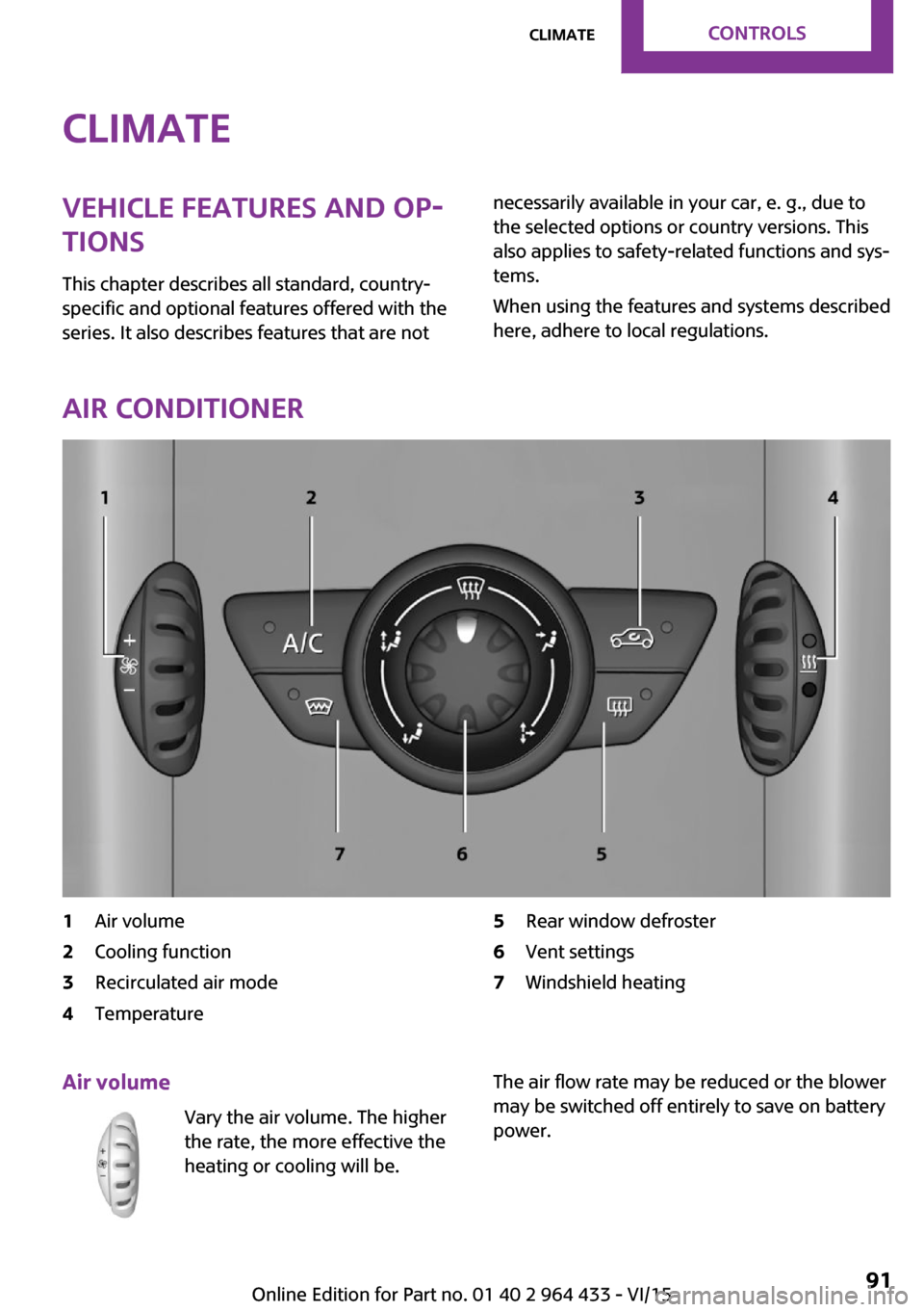
Air conditioner
1Air volume2Cooling function3Recirculated air mode4Temperature5Rear window defroster6Vent settings7Windshield heatingAir volume
Vary the air volume. The higher
the rate, the more effective the
heating or cooling will be.The air flow rate may be reduced or the blower
may be switched off entirely to save on battery
power.Seite 91ClimateCONTROLS91
Online Edition for Part no. 01 40 2 964 433 - VI/15
Page 92 of 223
Switching the system on/offTurn the rotary switch for the air volume to 0.
The blower and air conditioner are completely switched off and the air supply is cut off.
Set any air volume to switch on the air condi‐
tioning.
Cooling function The car's interior can only be
cooled with the engine running.
The cooling function cools and
dehumidifies the incoming air
before reheating it as required,
according to the temperature setting.
The cooling function helps to prevent conden‐
sation on the windows or to remove it quickly.
Depending on the weather, the windshield may
fog up briefly when the engine is started.
To cool the air faster and more intensively
when external temperatures are high, switch
on the recirculated air mode.
Recirculated air mode If the air outside the car has an
unpleasant odor or contains pol‐
lutants, shut off the supply to the
interior of the car temporarily.
The system then recirculates the
air currently within the vehicle.
Should the windows fog up in the recirculated-
air mode, press the AUTO button or switch off
the recirculated-air mode and increase the air
volume if necessary. Make sure that air can
flow to the windshield.
Recirculated air mode is automatically deacti‐
vated at low external temperatures.
With constant recirculated-air mode, the air
quality in the car's interior deteriorates and the
fogging of the windows increases.Temperature
Turn upward, red, to raise thetemperature.
Turn downward, blue, to lower
the temperature.
Rear window defroster The rear window defroster
switches off automatically after a
certain period of time.
The rear window defroster
power may be lowered or even
switched off entirely to save on battery power.
Vent settings Direct the flow of air to the win‐
dows
, to the upper body
area
, or to the footwell .
Intermediate positions are possi‐
ble.
Windshield heating The windshield heating switches
off automatically after some
time.
The windshield heating may be
reduced or even switched off en‐
tirely to save on battery power.
Defrosting and defogging windows
1.Set the maximum air volume.2.Air distribution in position .
By switching on the cooling function, the
windows are defogged more rapidly.3.Set the highest temperature, red.4.Deactivate recirculated air mode.5.Switch on the windshield heating if neces‐
sary.6.Switch on the rear window defroster if nec‐
essary.Seite 92CONTROLSClimate92
Online Edition for Part no. 01 40 2 964 433 - VI/15
Page 107 of 223

Ventilation
Depending on the vehicle's equipment, the
glove compartment can be ventilated and, if the cooling function is switched on, cooled.
Opening
Turn the switch in the direction of the arrow.
ClosingMove the switch to the vertical position by
turning it in the opposite direction of the arrow.
Depending on the temperature setting of the
air conditioning or automatic climate control,
high temperatures may occur in the glove com‐
partment.
Center armrest
The center armrest between the front seats
contains a storage compartment or a cover for
the snap-in adapter, refer to page 145, de‐
pending on the equipment.
Do not position tall accessory parts directly on
the center rail of the center armrest; otherwise, they may be damaged when the center arm‐
rest is opened or closed.
Center armrest front
Opening
Press the button, arrow, and pull up the lid.
Center rail
Rail segment
The rail segment can be used to secure various
objects that are placed into the rail against slip‐
ping, such as a ball point pen or smartphone.
In addition, the connection cable of the smart‐
phone can be secured using the rail segment.
1.Twist the rail segment, arrow 1, to remove
it.2.Insert the connection cable centrally into
the recess, arrow 2.3.Fix the rail segment in the rail.
Clothes hooks
Clothes hooks are located on the grab handles
in the rear.
WARNING
Clothing articles on the clothes hooks can
obstruct the view while driving. There is risk of
an accident. When suspending clothing articles
Seite 107Storage compartmentsCONTROLS107
Online Edition for Part no. 01 40 2 964 433 - VI/15
Page 141 of 223
Connecting a particular mobile phone1.Switch on the radio ready state or the igni‐
tion.2. Press the button.3."PHONE"4."BT"5.Turn the right knob until the mobile phone
to be connected is displayed.6."PRIO"
Press the button repeatedly until the de‐
sired position is reached.
Unpairing the mobile phone
1.Switch on the radio ready state or the igni‐
tion.2. Press the button.3."PHONE"4."BT"5.Turn the right knob until the mobile phone
to be unpaired is displayed.6."DELETE"7."YES"
What to do if...
Information on compatible mobile phones, re‐
fer to page 138.
The mobile phone could not be paired or con‐
nected.
▷Is Bluetooth activated in the vehicle and on
the mobile phone? Activate Bluetooth on
the vehicle and on the mobile phone.▷Do the Bluetooth passkeys on the mobile
phone and the vehicle match? Enter the
same passkey on the mobile phone and on
the radio.▷Did it take longer than 30 seconds to enter
the passkey? Repeat the pairing procedure.▷Are too many Bluetooth devices connected
to the mobile phone or vehicle? Delete con‐
nections with other devices if necessary.▷Is the mobile phone in power-save mode or
does it have only a limited remaining bat‐
tery life? Charge the mobile phone in the
snap-in adapter or via the charging cable.▷Depending on the mobile phone, it is possi‐
ble that only one mobile phone can be con‐
nected to the vehicle. Unpair the connected
mobile phone from the vehicle and pair
and connect only one mobile phone.
The mobile phone no longer reacts?
▷Switch the mobile phone off and on again.▷Is the ambient temperature too high or
low? Do not expose the mobile phone to
extreme environmental conditions.
No phone book entries or only some phone
book entries are displayed, or they are incom‐
plete.
▷Transmission of the phone book entries is
not yet complete.▷It is possible that only the phone book en‐
tries of the mobile phone or the SIM card
are transmitted.▷It may not be possible to display phone
book entries with special characters.▷The number of phone book entries to be
stored is too high.▷Is the data volume of the contact too large,
e. g., due to stored information such as
notes? Reduce the data volume of the con‐
tact.
The phone connection quality is poor.
▷The strength of the Bluetooth signal on the
mobile phone can be adjusted, depending
on the mobile phone.▷Insert the mobile phone into the snap-in
adapter or place it in the area of the center
console.▷Adjust the volume of the microphone and
loudspeakers.Seite 141TelephoneCOMMUNICATION141
Online Edition for Part no. 01 40 2 964 433 - VI/15