display MINI Paceman 2016 Workshop Manual
[x] Cancel search | Manufacturer: MINI, Model Year: 2016, Model line: Paceman, Model: MINI Paceman 2016Pages: 223, PDF Size: 5.52 MB
Page 144 of 223

4.Enter additional digits on the buttons 0–9.5.Press the right knob to dial the phone num‐
ber.
Dialing a phone number from the phone
book using the buttons on the steering
wheel
1. Press and hold the button to dis‐
play the Telephone menu.2.Press the arrow buttons on the steering
wheel to leaf through the phone book.3. Press the button to dial the phone
number.
Dialing a phone number stored in a list
To select an entry and establish a connection:
1.Switch on the radio ready state or the igni‐
tion.2. Press the button.3."PHONE"4.Select a list, for instance "TOP8"5.Turn the right knob to select an entry and
press the knob to dial the phone number.
Deleting an individual entry
1.Select an entry from the list.2."DEL"
DTMF suffix dialing
DTMF suffix dialing can be used for gaining ac‐
cess to network services or for controlling devi‐
ces, e.g., to make a remote inquiry of an an‐
swering machine. The DTMF code is needed for
this purpose.
This function is only available if a connection
exists and if the hands-free system is being
used.
1."KEYPAD"2.Enter the DTMF code on the buttons 0–9.3.If necessary, press and hold the function
button on the right or left to enter special
characters.
Displaying the call duration
During a call:
"DURAT"
Hands-free system
General information
Calls that are being made on the hands-free
system can be continued on the mobile phone
and vice versa.
From the mobile phone to the hands-
free system
Calls that were begun outside of the Bluetoothrange of the vehicle can be continued on the
hands-free system with the ignition switched
on.
Depending on the mobile phone, the system
automatically switches to the hands-free sys‐
tem.
If the system does not switch over automati‐
cally, follow the instructions on the mobile
phone display; refer also to the mobile phone
operating instructions.
From the hands-free system to the
mobile phone
Calls that are made on the hands-free system
can in some cases be continued on the mobile
phone; this depends on the mobile phone.
Follow the instructions on the mobile phone
display; refer also to the mobile phone operat‐
ing instructions.
MINI phone numbers When the ignition is switched on, various serv‐ice phone numbers can be displayed.
Seite 144COMMUNICATIONTelephone144
Online Edition for Part no. 01 40 2 964 433 - VI/15
Page 145 of 223

▷"Road Assist": Roadside Assistance, if help
is required in the event of a breakdown.▷"Serv. Appt.": MINI service center, if a serv‐
ice appointment needs to be arranged.▷"Cust Relat": Customer Relations, for infor‐
mation on all aspects of your vehicle.
Displaying the phone numbers
1.Switch on the radio ready state or the igni‐
tion.2. Press the button.3."MINI"4.Turn the right knob until the desired phone
number is displayed.
Snap-in adapter
General information For more information about snap-in adapters
that support the functions of the mobile phone
in a compatible way, contact a dealer's service
center or another qualified service center or re‐
pair shop.
Information At high temperatures, the charging function of
the mobile phone may be limited and functions
may not be executed.
When using the mobile phone via the vehicle,
note the operating instructions of the mobile
phone.
Installation position
In the center armrest.
Inserting/removing the snap-in adapter1.Press the button, arrow 1, and remove the
cover, arrow 2.2.Insert the snap-in adapter at the front, ar‐
row 1, and press down, arrow 2, until it en‐
gages.
To remove:
To remove the snap-in adapter, press the but‐
ton.
Inserting the mobile phone
1.Depending on the mobile phone, remove
the protective cap from the antenna con‐
nector and from the USB connection of the
mobile phone.2.With the buttons facing up, slide the mobile
phone up toward the electrical contacts, ar‐Seite 145TelephoneCOMMUNICATION145
Online Edition for Part no. 01 40 2 964 433 - VI/15
Page 150 of 223
RefuelingVehicle features and op‐
tions
This chapter describes all standard, country-
specific and optional features offered with the
series. It also describes features that are not necessarily available in your car, e. g., due to
the selected options or country versions. This
also applies to safety-related functions and sys‐
tems.
When using the features and systems described
here, adhere to local regulations.
General information CAUTION
With a range of less than 30 miles/50 km
it is possible that the engine will no longer have
sufficient fuel. Engine functions are no longer
ensured. There is risk of property damage. Re‐
fuel promptly. ◀
Fuel cap
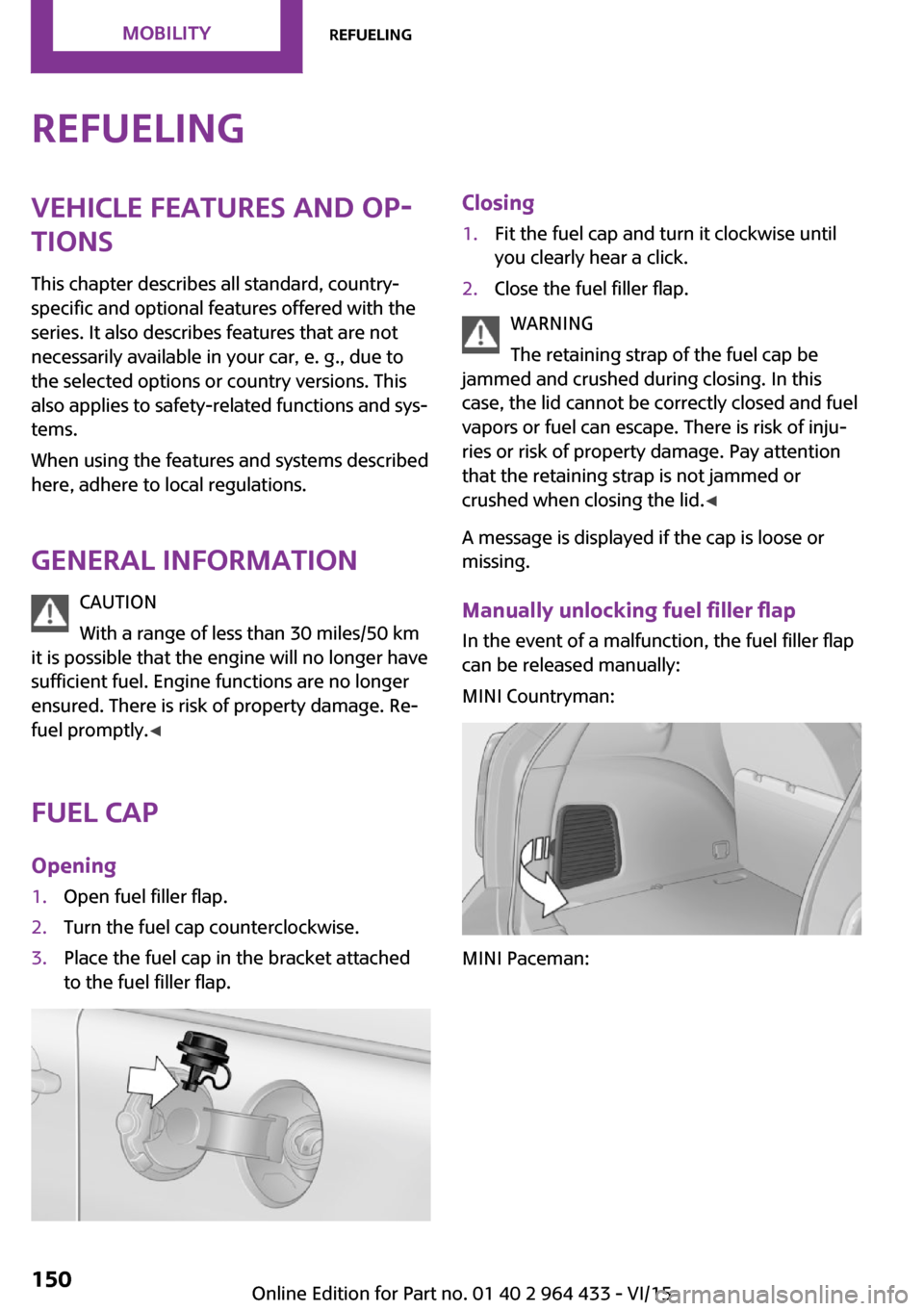
Opening1.Open fuel filler flap.2.Turn the fuel cap counterclockwise.3.Place the fuel cap in the bracket attached
to the fuel filler flap.Closing1.Fit the fuel cap and turn it clockwise until
you clearly hear a click.2.Close the fuel filler flap.
WARNING
The retaining strap of the fuel cap be
jammed and crushed during closing. In this
case, the lid cannot be correctly closed and fuel
vapors or fuel can escape. There is risk of inju‐
ries or risk of property damage. Pay attention
that the retaining strap is not jammed or
crushed when closing the lid. ◀
A message is displayed if the cap is loose or
missing.
Manually unlocking fuel filler flap In the event of a malfunction, the fuel filler flap
can be released manually:
MINI Countryman:
MINI Paceman:
Seite 150MOBILITYRefueling150
Online Edition for Part no. 01 40 2 964 433 - VI/15
Page 161 of 223
Wheel and tire combination
Information on the right wheel/tire combina‐
tion and wheel rim versions for your vehicle can
be obtained from the dealer’s service center or
another qualified service center or repair shop.
Incorrect wheel and tire combinations impair
the function of a variety of systems such as ABS
or DSC.
To maintain good handling and vehicle re‐
sponse, use only tires with a single tread con‐
figuration from a single manufacturer.
Following tire damage, have the original wheel
and tire combination remounted on the vehicle
as soon as possible.
WARNING
Wheels and tires which are not suitable
for your vehicle can damage parts of the vehi‐
cle, e.g. due to contact with the body due to
tolerances despite the same official size rating.
There is risk of an accident. ◀
Wheels with electronics for TPM Tire
Pressure Monitor
When mounting new tires or changing from
summer to winter tires or vice versa, only use
wheels with TPM electronics; otherwise, the
Tire Pressure Monitor will not be able to detect
a flat tire, refer to page 79. A dealer’s service
center will be glad to answer any questions you
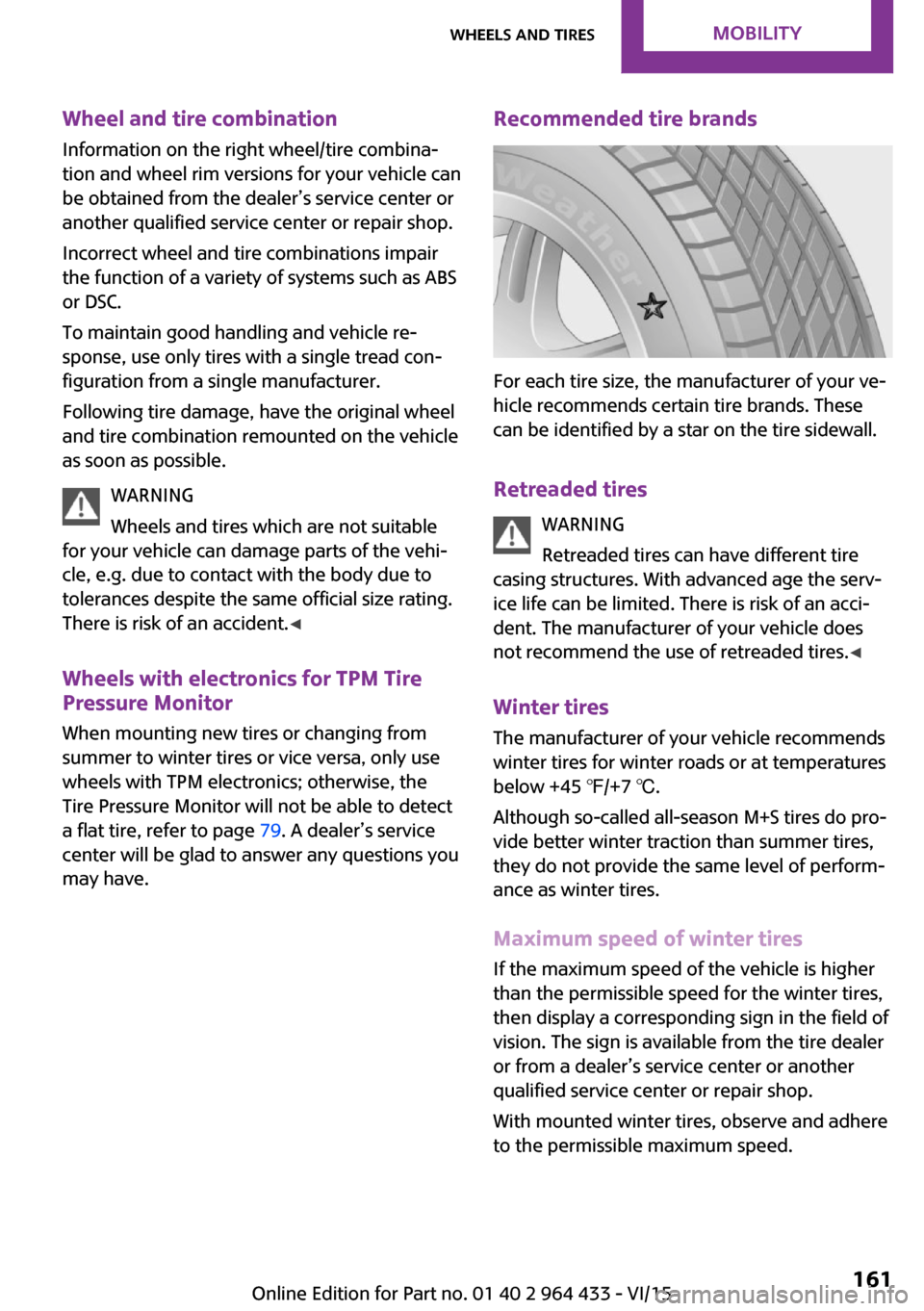
may have.Recommended tire brands
For each tire size, the manufacturer of your ve‐
hicle recommends certain tire brands. These
can be identified by a star on the tire sidewall.
Retreaded tires WARNING
Retreaded tires can have different tire
casing structures. With advanced age the serv‐
ice life can be limited. There is risk of an acci‐
dent. The manufacturer of your vehicle does
not recommend the use of retreaded tires. ◀
Winter tires The manufacturer of your vehicle recommendswinter tires for winter roads or at temperatures
below +45 ℉/+7 ℃.
Although so-called all-season M+S tires do pro‐
vide better winter traction than summer tires, they do not provide the same level of perform‐
ance as winter tires.
Maximum speed of winter tires
If the maximum speed of the vehicle is higher
than the permissible speed for the winter tires,
then display a corresponding sign in the field of
vision. The sign is available from the tire dealer
or from a dealer’s service center or another
qualified service center or repair shop.
With mounted winter tires, observe and adhere
to the permissible maximum speed.
Seite 161Wheels and tiresMOBILITY161
Online Edition for Part no. 01 40 2 964 433 - VI/15
Page 163 of 223

▷Use of the Mobility System may be ineffec‐
tive if tire damage is greater than approx.
1/8 in/4 mm in size.▷Contact a dealer’s service center or another
qualified service center or repair shop if the
tire cannot be made drivable.▷If possible, do not remove foreign bodies
that have penetrated the tire.▷Pull the speed limit sticker off the sealant
bottle and apply it to the steering wheel.
Sealant and compressor
1Sealant bottle and speed limit sticker2Filling hose
Note the use-by date on the sealant bottle.3Holder for the sealant bottle4Compressor5Connector and cable for the lighter socket/
socket in passenger compartment 101.6Connection hose for connecting the com‐
pressor and sealant bottle or the compres‐
sor and wheel7On/off switch8Pressure gauge for displaying the tire infla‐
tion pressure9Release button for reducing the tire infla‐
tion pressure
The connector, cable, and connecting hose are
stowed in the compressor housing.
Using the Mobility System
To repair a flat tire with the Mobility System,
proceed as follows:
▷Filling the tire with sealant▷Distributing the sealant▷Correcting the tire inflation pressure
Filling the tire with sealant
1.Shake the sealant bottle.2.Pull the connection hose 6 fully out of the
compressor housing and screw it onto the
sealant bottle connection. Ensure that the
connection hose is not kinked.3.Insert the sealant bottle into the compres‐
sor housing in a vertical position.4.Unscrew the dust cap off of the valve of the
not working wheel and screw the filling
hose 2 of the sealant bottle onto the valve.5.Ensure that the compressor is switched off.6.Insert connector 5 into the lighter socket/
socket in the passenger compartment, refer
to page 101.7.When the engine is running:Seite 163Wheels and tiresMOBILITY163
Online Edition for Part no. 01 40 2 964 433 - VI/15
Page 168 of 223

Engine oilEngine oil
Vehicle features and options This chapter describes all standard, country-
specific and optional features offered with the series. It also describes features that are notnecessarily available in your car, e. g., due to
the selected options or country versions. This
also applies to safety-related functions and sys‐
tems.
When using the features and systems described
here, adhere to local regulations.
General information
Engine oil consumption depends on the driving
style and the conditions of use. A highly sporty
driving style, for example, results in considera‐
bly higher engine oil consumption.
Therefore, regularly check the engine oil level
after refueling.
Checking the oil level with a dip stick1.Park the vehicle on level ground when the
engine is at operating temperature, i.e., af‐
ter driving continuously for at least
6 2 miles/10 km.2.Switch the engine off.3.After approx. 5 minutes, pull out the dip
stick and wipe it off with a lint-free cloth,
paper towel, etc.4.Carefully insert the dip stick all the way into
the measuring tube and pull it out again.The oil level must be between the two
marks on the dip stick.
The oil quantity between the two marks on the
dip stick equals approx. 1 US quart/1 liter.
Do not exceed the high mark of the dip stick.
Adding engine oil
Filler neck
Add a maximum quantity of 1 US quart/1 liter
of oil only after the corresponding message ap‐
pears on the Control Display or, in diesel en‐
gines, after the oil level is just above the low
mark of the dip stick, refer to page 168.
CAUTION
A too low engine oil level causes engine
damage. There is risk of property damage.
Add engine oil within the next
30 miles/50 km. ◀
Seite 168MOBILITYEngine oil168
Online Edition for Part no. 01 40 2 964 433 - VI/15
Page 172 of 223
MaintenanceVehicle features and op‐
tions
This chapter describes all standard, country-
specific and optional features offered with the
series. It also describes features that are not
necessarily available in your car, e. g., due to
the selected options or country versions. This
also applies to safety-related functions and sys‐
tems.
When using the features and systems described
here, adhere to local regulations.
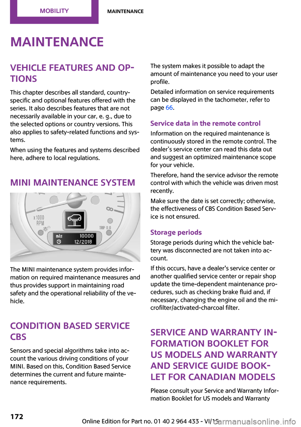
MINI maintenance system
The MINI maintenance system provides infor‐
mation on required maintenance measures and
thus provides support in maintaining road
safety and the operational reliability of the ve‐
hicle.
Condition Based Service
CBS
Sensors and special algorithms take into ac‐
count the various driving conditions of your
MINI. Based on this, Condition Based Service
determines the current and future mainte‐
nance requirements.
The system makes it possible to adapt the
amount of maintenance you need to your user
profile.
Detailed information on service requirements
can be displayed in the tachometer, refer to
page 66.
Service data in the remote control Information on the required maintenance is
continuously stored in the remote control. The
dealer’s service center can read this data out
and suggest an optimized maintenance scope
for your vehicle.
Therefore, hand the service advisor the remote
control with which the vehicle was driven most
recently.
Make sure the date is set correctly; otherwise,
the effectiveness of CBS Condition Based Serv‐
ice is not ensured.
Storage periods
Storage periods during which the vehicle bat‐
tery was disconnected are not taken into ac‐
count.
If this occurs, have a dealer's service center or
another qualified service center or repair shop
update the time-dependent maintenance pro‐
cedures, such as checking brake fluid and, if
necessary, changing the engine oil and the mi‐ crofilter/activated-charcoal filter.
Service and Warranty In‐formation Booklet for
US models and Warranty
and Service Guide Book‐
let for Canadian models
Please consult your Service and Warranty Infor‐
mation Booklet for US models and WarrantySeite 172MOBILITYMaintenance172
Online Edition for Part no. 01 40 2 964 433 - VI/15
Page 173 of 223
and Service Guide Booklet for Canadian models
for additional information on service require‐
ments.
The manufacturer of your vehicle recommends
that maintenance and repair be performed by a
dealer’s service center or another qualified
service center or repair shop. Records of regu‐
lar maintenance and repair work should be re‐
tained.
Socket for OBD Onboard
Diagnosis
CAUTION
The socket for Onboard Diagnosis is an
intricate component intended to be used in
conjunction with specialized equipment to
check the vehicle’s primary emissions system.
Improper use of the socket for Onboard Diag‐
nosis, or contact with the socket for Onboard
Diagnosis for other than its intended purpose,
can cause vehicle malfunctions and creates
risks of personal and property damage. Given
the foregoing, the manufacture of your vehicle
strongly recommends that access to the socket
for Onboard Diagnosis be limited to a dealer's
service center or another qualified service cen‐
ter or repair shop or other persons that have
the specialized training and equipment for pur‐
poses of properly utilizing the socket for On‐
board Diagnosis. ◀
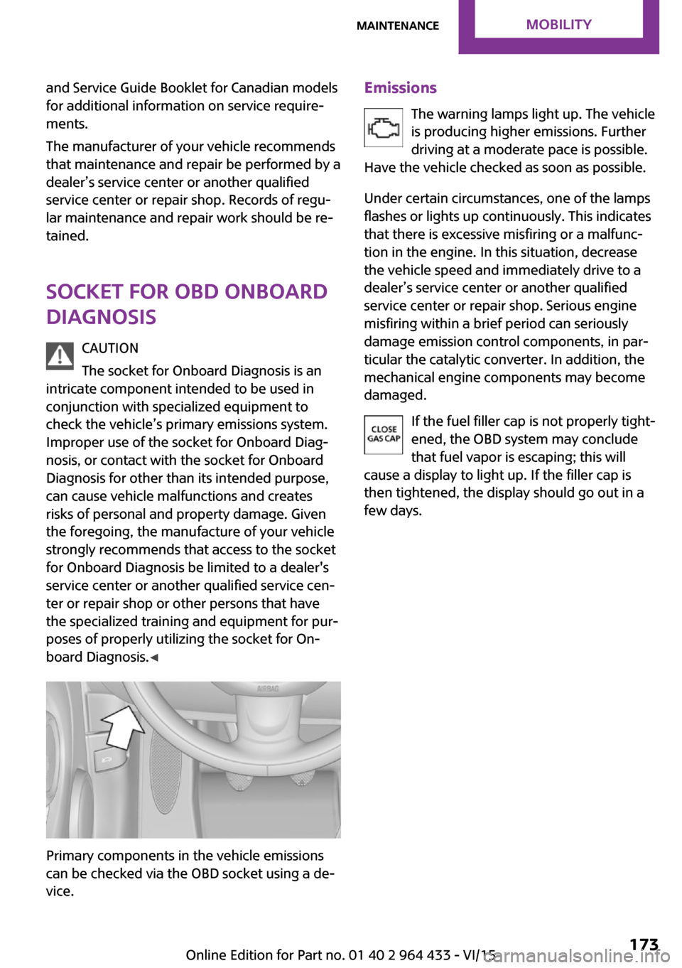
Primary components in the vehicle emissions
can be checked via the OBD socket using a de‐
vice.
Emissions
The warning lamps light up. The vehicle
is producing higher emissions. Further
driving at a moderate pace is possible.
Have the vehicle checked as soon as possible.
Under certain circumstances, one of the lamps
flashes or lights up continuously. This indicates
that there is excessive misfiring or a malfunc‐
tion in the engine. In this situation, decrease
the vehicle speed and immediately drive to a
dealer’s service center or another qualified
service center or repair shop. Serious engine
misfiring within a brief period can seriously
damage emission control components, in par‐
ticular the catalytic converter. In addition, the
mechanical engine components may become
damaged.
If the fuel filler cap is not properly tight‐
ened, the OBD system may conclude
that fuel vapor is escaping; this will
cause a display to light up. If the filler cap is
then tightened, the display should go out in a
few days.Seite 173MaintenanceMOBILITY173
Online Edition for Part no. 01 40 2 964 433 - VI/15
Page 182 of 223
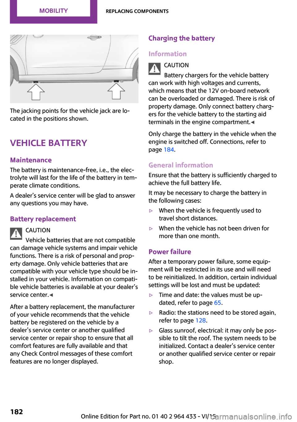
The jacking points for the vehicle jack are lo‐
cated in the positions shown.
Vehicle battery Maintenance
The battery is maintenance-free, i.e., the elec‐
trolyte will last for the life of the battery in tem‐
perate climate conditions.
A dealer’s service center will be glad to answer
any questions you may have.
Battery replacement CAUTION
Vehicle batteries that are not compatible
can damage vehicle systems and impair vehicle
functions. There is a risk of personal and prop‐
erty damage. Only vehicle batteries that are
compatible with your vehicle type should be in‐
stalled in your vehicle. Information on compati‐
ble vehicle batteries is available at your dealer’s
service center. ◀
After a battery replacement, the manufacturer
of your vehicle recommends that the vehicle
battery be registered on the vehicle by a
dealer’s service center or another qualified
service center or repair shop to ensure that all
comfort features are fully available and that
any Check Control messages of these comfort
features are no longer displayed.
Charging the battery
Information CAUTION
Battery chargers for the vehicle battery
can work with high voltages and currents, which means that the 12V on-board network
can be overloaded or damaged. There is risk of
property damage. Only connect battery charg‐
ers for the vehicle battery to the starting aid
terminals in the engine compartment. ◀
Only charge the battery in the vehicle when the
engine is switched off. Connections, refer to
page 184.
General information
Ensure that the battery is sufficiently charged to
achieve the full battery life.
It may be necessary to charge the battery in
the following cases:▷When the vehicle is frequently used to
travel short distances.▷When the vehicle has not been driven for
more than one month.
Power failure
After a temporary power failure, some equip‐
ment will be restricted in its use and will need
to be reinitialized. In addition, certain individual
settings will be lost and must be updated:
▷Time and date: the values must be up‐
dated, refer to page 65.▷Radio: the stations need to be stored again,
refer to page 128.▷Glass sunroof, electrical: it may only be pos‐
sible to tilt the roof. The system needs to be
initialized. Contact a dealer’s service center
or another qualified service center or repair
shop.Seite 182MOBILITYReplacing components182
Online Edition for Part no. 01 40 2 964 433 - VI/15
Page 184 of 223
Breakdown assistanceVehicle features and op‐
tions
This chapter describes all standard, country-
specific and optional features offered with the
series. It also describes features that are not
necessarily available in your car, e. g., due to
the selected options or country versions. This
also applies to safety-related functions and sys‐
tems.
When using the features and systems described
here, adhere to local regulations.
Hazard warning flash‐
ers
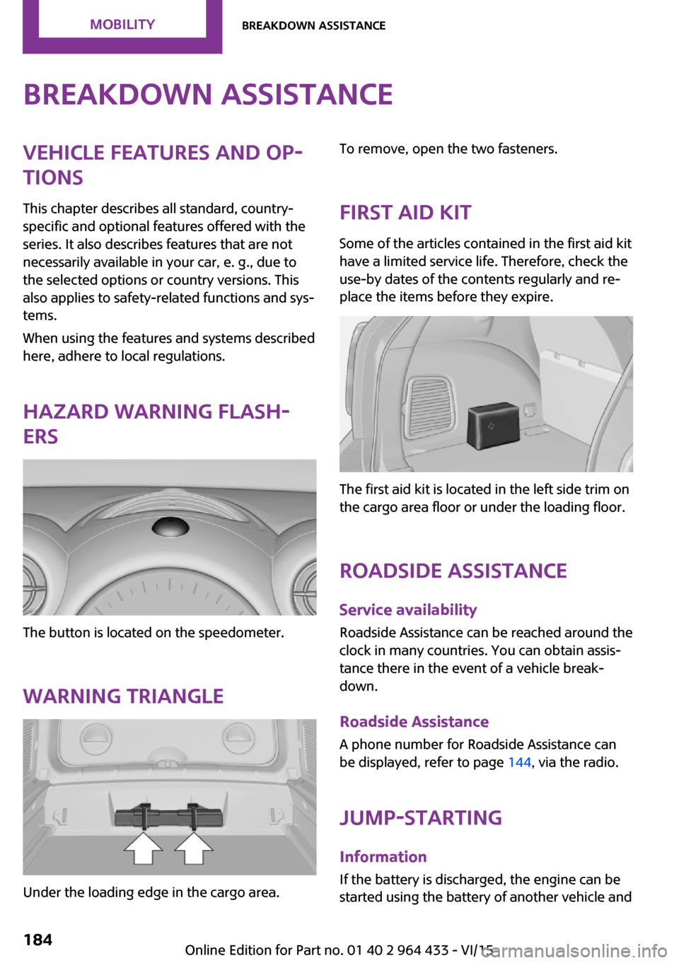
The button is located on the speedometer.
Warning triangle
Under the loading edge in the cargo area.
To remove, open the two fasteners.
First aid kit Some of the articles contained in the first aid kit
have a limited service life. Therefore, check the
use-by dates of the contents regularly and re‐
place the items before they expire.
The first aid kit is located in the left side trim on
the cargo area floor or under the loading floor.
Roadside Assistance Service availability
Roadside Assistance can be reached around the
clock in many countries. You can obtain assis‐
tance there in the event of a vehicle break‐
down.
Roadside Assistance A phone number for Roadside Assistance can
be displayed, refer to page 144, via the radio.
Jump-starting InformationIf the battery is discharged, the engine can be
started using the battery of another vehicle and
Seite 184MOBILITYBreakdown assistance184
Online Edition for Part no. 01 40 2 964 433 - VI/15