Convertible MINI Roadster 2013 Owner's Guide
[x] Cancel search | Manufacturer: MINI, Model Year: 2013, Model line: Roadster, Model: MINI Roadster 2013Pages: 292, PDF Size: 7.02 MB
Page 63 of 292
Attaching the upper retaining strap to
the mounting point
MINI Coupe1.Remove the front cargo cover, refer to
page 115.2.Slide the head restraint upward.3.Guide the tether strap between the head
restraint supports.4.Hook in the tether strap on the mounting
point with the hook.5.Slide the head restraint into the bottom po‐
sition.6.Pull the tether strap taut.
MINI Convertible
Ensure that the upper retaining strap 9 is
passed between backrest 8 and rollover protec‐
tion system with crossbar 3; otherwise, it will be
unable to properly restrain the child restraint
fixing system.
1.Slide the head restraint upward.2.Unlock the backrest and fold it forward
slightly, refer to page 117.3.Guide the tether strap between the head
restraint supports.4.Hook in the tether strap on the mounting
point with the hook.5.Fold back the backrest and lock it. Slide the
head restraint down as far as possible.6.Pull the tether strap taut.Seite 63Transporting children safelyControls63
Online Edition for Part no. 01 40 2 919 017 - II/13
Page 76 of 292
▷Average speed.▷MINI Roadster, MINI Convertible: Always
Open Timer.
To set the corresponding units of measure, re‐
fer to page 78.
Information in detail
Range
Displays the estimated cruising range available
with the remaining fuel.
It is calculated based on your driving style over
the last 18 miles/30 km.
Average fuel consumption
This is calculated for the period during which
the engine is running.
With the trip computer, refer to page 76, the
average consumption can be displayed for an
additional distance.
To reset the average consumption: press the
button on the turn indicator lever for ap‐
prox. 2 seconds.
Current fuel consumption Displays the current fuel consumption. You can
check whether you are currently driving in an
efficient and environmentally-friendly manner.
Average speed Periods in which the vehicle was parked and
the engine was switched off manually are not
included in the average speed calculations.
With the trip computer, refer to page 76, the
average speed can be displayed for an addi‐
tional distance.
To reset the average speed: press the button
on the turn indicator lever for approx. 2 sec‐
onds.
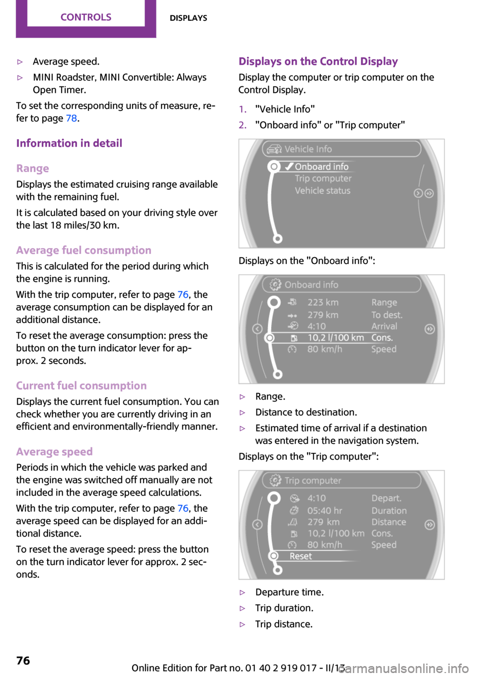
Displays on the Control Display
Display the computer or trip computer on the
Control Display.1."Vehicle Info"2."Onboard info" or "Trip computer"
Displays on the "Onboard info":
▷Range.▷Distance to destination.▷Estimated time of arrival if a destination
was entered in the navigation system.
Displays on the "Trip computer":
▷Departure time.▷Trip duration.▷Trip distance.Seite 76ControlsDisplays76
Online Edition for Part no. 01 40 2 919 017 - II/13
Page 77 of 292
Both displays show:▷Average fuel consumption.▷Average speed.
Resetting the fuel consumption and
speed
Resetting the values for average speed and
average fuel consumption:
1.Select the respective menu item and press
the MINI joystick.2.Press the MINI joystick again to confirm
your selection.
Resetting the trip computer
Resetting all values:
1."Vehicle Info"2."Trip computer"3."Reset"
Always Open Timer
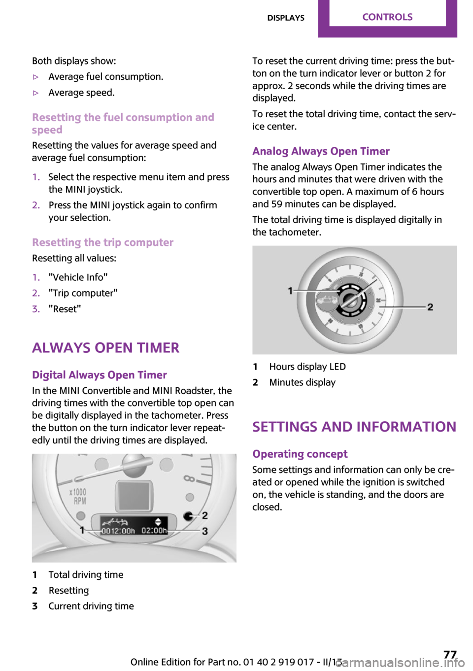
Digital Always Open Timer In the MINI Convertible and MINI Roadster, the
driving times with the convertible top open can
be digitally displayed in the tachometer. Press
the button on the turn indicator lever repeat‐
edly until the driving times are displayed.
1Total driving time2Resetting3Current driving timeTo reset the current driving time: press the but‐
ton on the turn indicator lever or button 2 for
approx. 2 seconds while the driving times are
displayed.
To reset the total driving time, contact the serv‐
ice center.
Analog Always Open Timer
The analog Always Open Timer indicates the
hours and minutes that were driven with the
convertible top open. A maximum of 6 hours
and 59 minutes can be displayed.
The total driving time is displayed digitally in
the tachometer.1Hours display LED2Minutes display
Settings and information
Operating concept
Some settings and information can only be cre‐
ated or opened while the ignition is switched
on, the vehicle is standing, and the doors are
closed.
Seite 77DisplaysControls77
Online Edition for Part no. 01 40 2 919 017 - II/13
Page 87 of 292
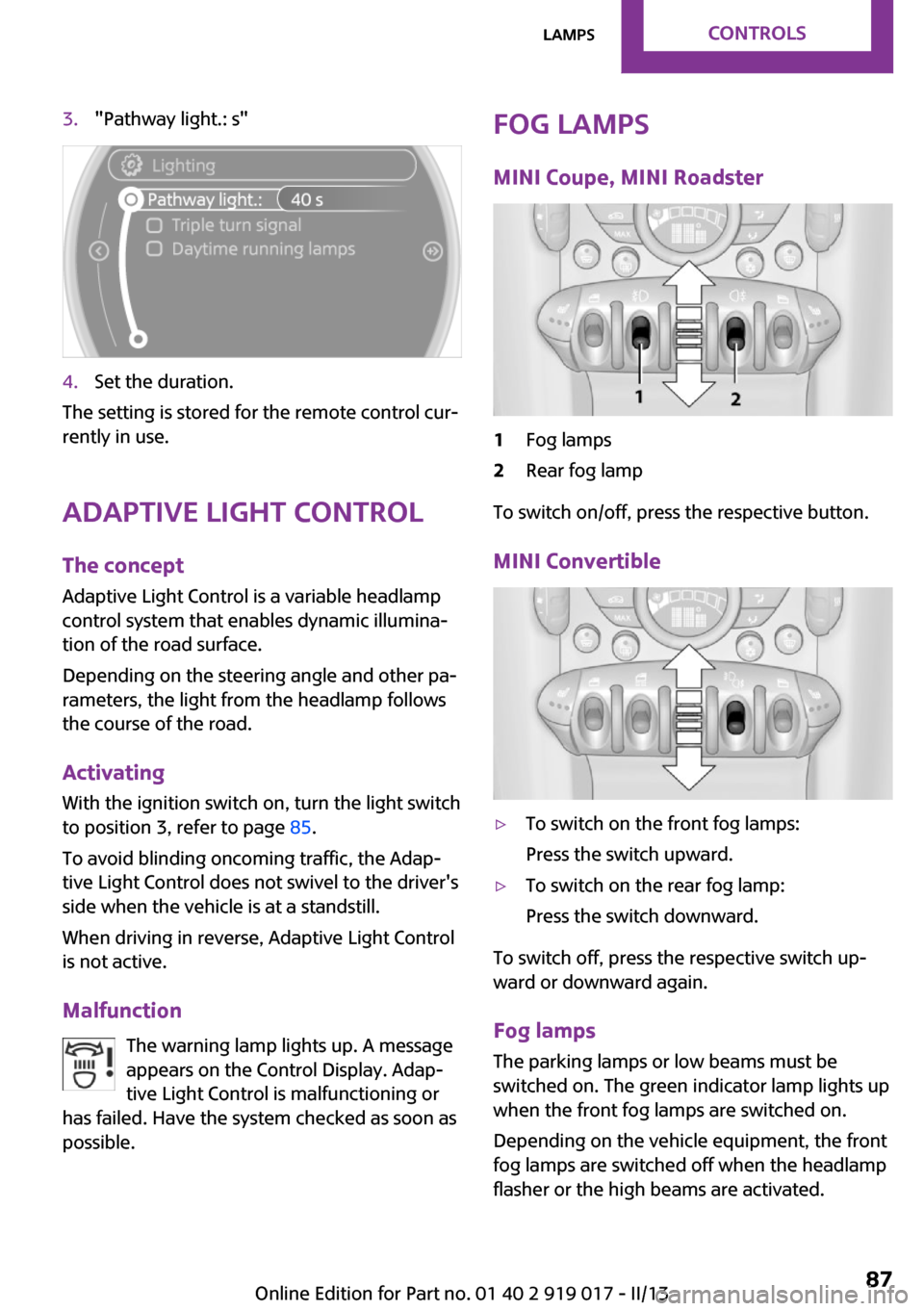
3."Pathway light.: s"4.Set the duration.
The setting is stored for the remote control cur‐
rently in use.
Adaptive Light Control
The concept
Adaptive Light Control is a variable headlamp
control system that enables dynamic illumina‐
tion of the road surface.
Depending on the steering angle and other pa‐
rameters, the light from the headlamp follows
the course of the road.
Activating
With the ignition switch on, turn the light switch
to position 3, refer to page 85.
To avoid blinding oncoming traffic, the Adap‐
tive Light Control does not swivel to the driver's
side when the vehicle is at a standstill.
When driving in reverse, Adaptive Light Control
is not active.
Malfunction The warning lamp lights up. A message
appears on the Control Display. Adap‐
tive Light Control is malfunctioning or
has failed. Have the system checked as soon as
possible.
Fog lamps
MINI Coupe, MINI Roadster1Fog lamps2Rear fog lamp
To switch on/off, press the respective button.
MINI Convertible
▷To switch on the front fog lamps:
Press the switch upward.▷To switch on the rear fog lamp:
Press the switch downward.
To switch off, press the respective switch up‐
ward or downward again.
Fog lamps
The parking lamps or low beams must be
switched on. The green indicator lamp lights up
when the front fog lamps are switched on.
Depending on the vehicle equipment, the front
fog lamps are switched off when the headlamp
flasher or the high beams are activated.
Seite 87LampsControls87
Online Edition for Part no. 01 40 2 919 017 - II/13
Page 88 of 292

If the automatic headlamp control is activated,
refer to page 85, the low beams are switched
on automatically when the front fog lamps are
switched on.
Rear fog lamp
The low beams or parking lamps with front fog
lamps must be switched on. The yellow indica‐
tor lamp lights up when the rear fog lamp is
switched on.
Instrument lighting
The parking lamps or low beams must be
switched on to adjust the brightness. The
brightness is increased to a certain limit and is
then reduced again.▷Press the button briefly: the brightness
changes in stages.▷Press and hold the button: the brightness
changes continuously.
Interior lamps
The interior lamps, the footwell lamps and the
cargo area lamp are controlled automatically.
To avoid draining the battery, all lamps inside
the vehicle are switched off some time after the
ignition is switched off.
Switching interior lamps on/off
manually
To switch the interior lamps on/off: press the
switch.
If the interior lamps are to remain switched off,
press the switch for approx. 3 seconds.
Reading lamps
Switching the reading lamps on/off
Press the switch.
MINI Roadster with semi-automatic convertible top
To switch on the interior lamps: press the
switch back.
Seite 88ControlsLamps88
Online Edition for Part no. 01 40 2 919 017 - II/13
Page 92 of 292
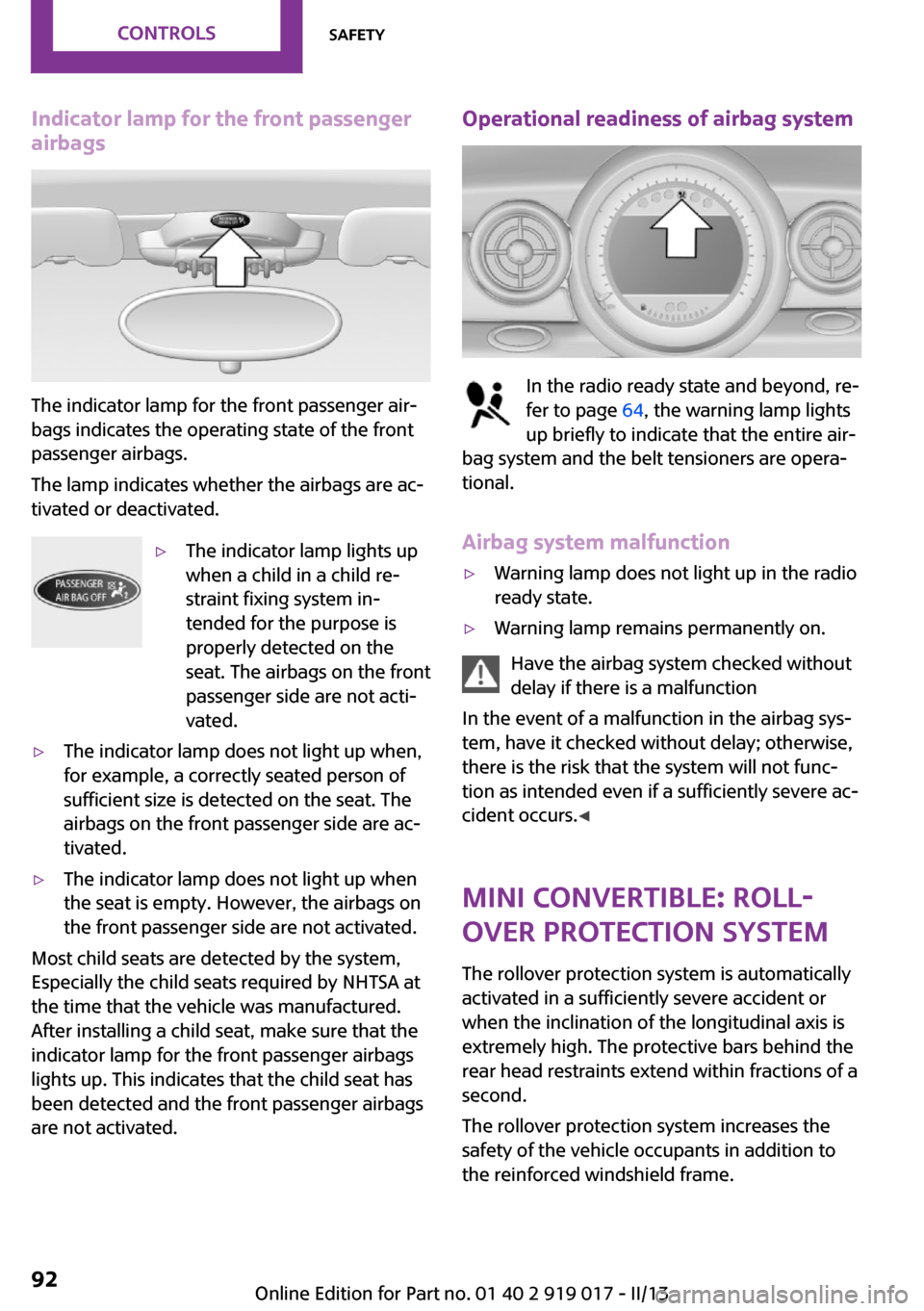
Indicator lamp for the front passenger
airbags
The indicator lamp for the front passenger air‐
bags indicates the operating state of the front
passenger airbags.
The lamp indicates whether the airbags are ac‐
tivated or deactivated.
▷The indicator lamp lights up
when a child in a child re‐
straint fixing system in‐
tended for the purpose is
properly detected on the
seat. The airbags on the front
passenger side are not acti‐
vated.▷The indicator lamp does not light up when,
for example, a correctly seated person of
sufficient size is detected on the seat. The
airbags on the front passenger side are ac‐
tivated.▷The indicator lamp does not light up when
the seat is empty. However, the airbags on
the front passenger side are not activated.
Most child seats are detected by the system,
Especially the child seats required by NHTSA at
the time that the vehicle was manufactured.
After installing a child seat, make sure that the
indicator lamp for the front passenger airbags
lights up. This indicates that the child seat has
been detected and the front passenger airbags
are not activated.
Operational readiness of airbag system
In the radio ready state and beyond, re‐
fer to page 64, the warning lamp lights
up briefly to indicate that the entire air‐
bag system and the belt tensioners are opera‐
tional.
Airbag system malfunction
▷Warning lamp does not light up in the radio
ready state.▷Warning lamp remains permanently on.
Have the airbag system checked without
delay if there is a malfunction
In the event of a malfunction in the airbag sys‐
tem, have it checked without delay; otherwise,
there is the risk that the system will not func‐
tion as intended even if a sufficiently severe ac‐
cident occurs. ◀
MINI Convertible: roll‐
over protection system
The rollover protection system is automatically
activated in a sufficiently severe accident or
when the inclination of the longitudinal axis is
extremely high. The protective bars behind the
rear head restraints extend within fractions of a
second.
The rollover protection system increases the
safety of the vehicle occupants in addition to
the reinforced windshield frame.
Seite 92ControlsSafety92
Online Edition for Part no. 01 40 2 919 017 - II/13
Page 93 of 292
Do not obstruct the area of movement
Always keep the area of movement of the
rollover protection system clear. In light acci‐
dents, you are protected by the fastened safety
belt and, depending on the severity of the acci‐
dent, the belt tightener and the multi-level air
bag restraint system. ◀
Lowering
Have the service center check the rollover pro‐
tection system after it is deployed unexpect‐
edly.
General instructions on the rollover pro‐
tection system
When the rollover protection system is ex‐
tended, do not move the convertible top under
any circumstances.
Do not modify the individual components of
the rollover protection system or the wiring in
any way.
Work on the rollover protection system should only be performed by a MINI service center.
Non-professional work on the system could
lead to failure or a malfunction.
To check the system and to ensure that the sys‐
tem will operate properly over the long-term, it
is imperative that you adhere to the specified
service intervals. ◀
FTM Flat Tire Monitor
The concept
The system does not measure the actual infla‐
tion pressure in the tires.
The system detects a pressure loss in a tire by
comparing the rotational speeds of the individ‐
ual wheels while moving.
In the event of a pressure loss, the diameter
and therefore the rotational speed of the corre‐
sponding wheel change. This is detected and
reported as a flat tire.Functional requirements
The system must have been initialized when
the tire inflation pressure was correct; other‐
wise, reliable signaling of a flat tire is not en‐
sured.
Initialize the system after each correction of the
tire inflation pressure and after every tire or
wheel change.
System limits Sudden tire damage
Sudden serious tire damage caused by
external influences cannot be indicated in ad‐
vance. ◀
A natural, even pressure loss in all four tires
cannot be detected. Therefore, check the tire
inflation pressure regularly.
The system could be delayed or malfunction in
the following situations:▷When the system has not been initialized.▷When driving on a snowy or slippery road
surface.▷Sporty driving style: slip in the drive wheels,
high lateral acceleration.▷When driving with snow chains.
When the vehicle is driven with a compact
wheel, refer to page 250, the Flat Tire Monitor
is not functional.
Status display
The current status of the Flat Tire Monitor can
be displayed on the Control Display, e.g., whether or not the FTM is active.
1."Vehicle Info"2."Vehicle status"Seite 93SafetyControls93
Online Edition for Part no. 01 40 2 919 017 - II/13
Page 111 of 292
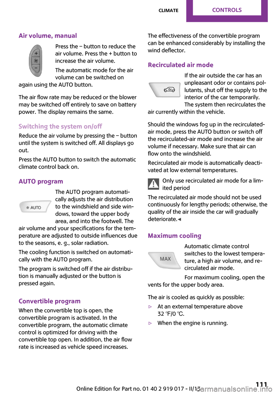
Air volume, manualPress the – button to reduce the
air volume. Press the + button to
increase the air volume.
The automatic mode for the air volume can be switched on
again using the AUTO button.
The air flow rate may be reduced or the blower
may be switched off entirely to save on battery
power. The display remains the same.
Switching the system on/off
Reduce the air volume by pressing the – button
until the system is switched off. All displays go
out.
Press the AUTO button to switch the automatic
climate control back on.
AUTO program The AUTO program automati‐
cally adjusts the air distribution
to the windshield and side win‐
dows, toward the upper body
area, and into the footwell. The
air volume and your specifications for the tem‐
perature are adjusted to outside influences due
to the seasons, e. g., solar radiation.
The cooling function is switched on automati‐
cally with the AUTO program.
The program is switched off if the air distribu‐
tion is manually adjusted or the button is
pressed again.
Convertible program When the convertible top is open, the
convertible program is activated. In the
convertible program, the automatic climate
control is optimized for driving with the
convertible top open. In addition, the air flow
rate is increased as vehicle speed increases.The effectiveness of the convertible program
can be enhanced considerably by installing the
wind deflector.
Recirculated air mode If the air outside the car has an
unpleasant odor or contains pol‐
lutants, shut off the supply to the
interior of the car temporarily.
The system then recirculates the
air currently within the vehicle.
Should the windows fog up in the recirculated-
air mode, press the AUTO button or switch off
the recirculated-air mode and increase the air
volume if necessary. Make sure that air can
flow onto the windshield.
Recirculated air mode is automatically deacti‐
vated at low external temperatures.
Only use recirculated air mode for a lim‐
ited period
The recirculated air mode should not be used continuously for lengthy periods; otherwise, the
quality of the air inside the car will gradually deteriorate. ◀
Maximum cooling Automatic climate control
switches to the lowest tempera‐
ture, a high air volume, and re‐
circulated air mode.
For maximum cooling, open the
vents for the upper body area.
The air is cooled as quickly as possible:▷At an external temperature above
32 ℉/0 ℃.▷When the engine is running.Seite 111ClimateControls111
Online Edition for Part no. 01 40 2 919 017 - II/13
Page 115 of 292
Avoid damaging the sockets by attempting to
insert plugs of unsuitable shape or size.
Do not connect the charger to the socket
Do not connect the battery charger to the
socket installed in the vehicle at the factory as
this could damage the battery. ◀
Replace the cover after use
Replace the lighter or socket cover after
use; otherwise, objects that fall into the lighter
socket or power socket could cause a short cir‐
cuit. ◀
Socket in the center console
Remove the cover or lighter, refer to page 114,
from the socket.
Socket in the cargo area
MINI Coupe, MINI Roadster
Take out the cover.
MINI Convertible
Take out the cover.
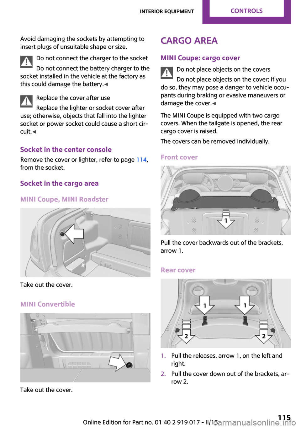
Cargo area MINI Coupe: cargo cover Do not place objects on the covers
Do not place objects on the cover; if you
do so, they may pose a danger to vehicle occu‐
pants during braking or evasive maneuvers or
damage the cover. ◀
The MINI Coupe is equipped with two cargo
covers. When the tailgate is opened, the rear
cargo cover is raised.
The covers can be removed individually.
Front cover
Pull the cover backwards out of the brackets,
arrow 1.
Rear cover
1.Pull the releases, arrow 1, on the left and
right.2.Pull the cover down out of the brackets, ar‐
row 2.Seite 115Interior equipmentControls115
Online Edition for Part no. 01 40 2 919 017 - II/13
Page 116 of 292
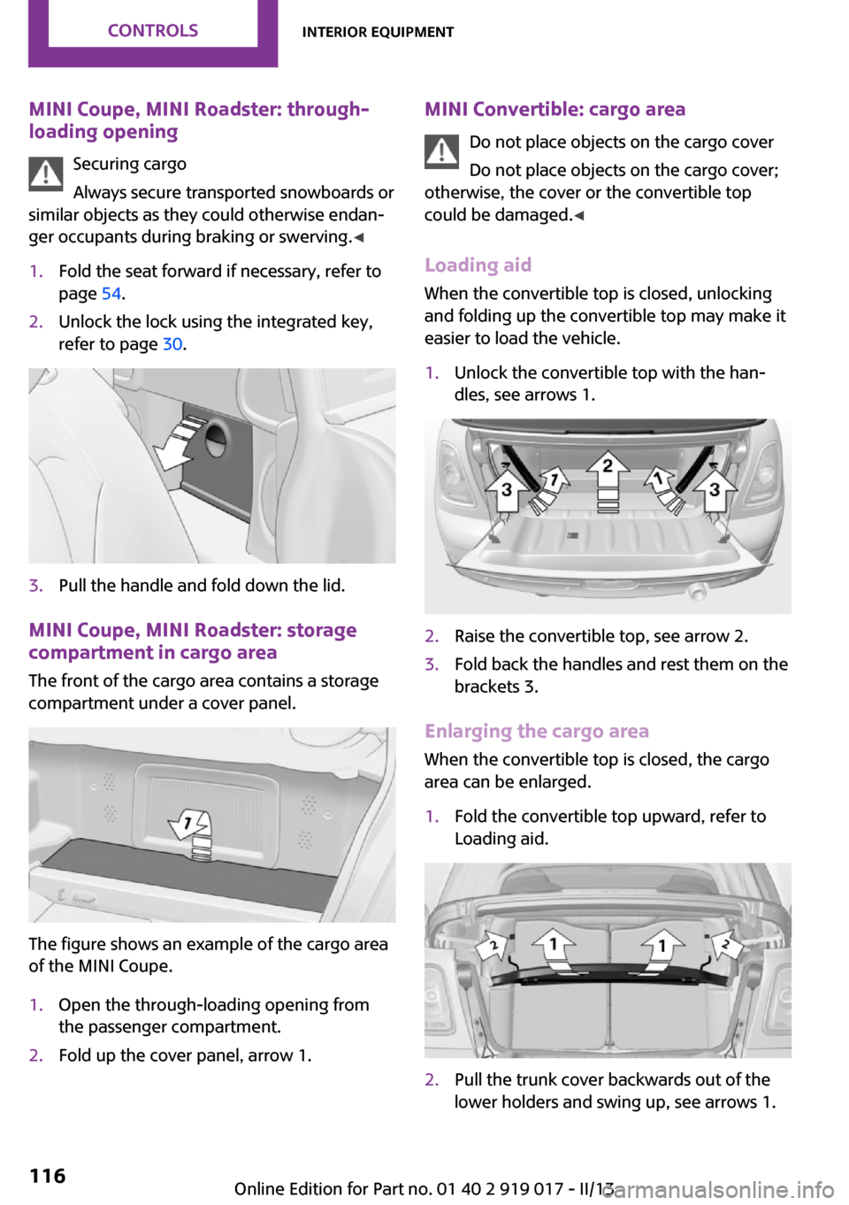
MINI Coupe, MINI Roadster: through-loading opening
Securing cargo
Always secure transported snowboards or
similar objects as they could otherwise endan‐
ger occupants during braking or swerving. ◀1.Fold the seat forward if necessary, refer to
page 54.2.Unlock the lock using the integrated key,
refer to page 30.3.Pull the handle and fold down the lid.
MINI Coupe, MINI Roadster: storage
compartment in cargo area
The front of the cargo area contains a storage
compartment under a cover panel.
The figure shows an example of the cargo area
of the MINI Coupe.
1.Open the through-loading opening from
the passenger compartment.2.Fold up the cover panel, arrow 1.MINI Convertible: cargo area
Do not place objects on the cargo cover
Do not place objects on the cargo cover;
otherwise, the cover or the convertible top
could be damaged. ◀
Loading aid When the convertible top is closed, unlocking
and folding up the convertible top may make it
easier to load the vehicle.1.Unlock the convertible top with the han‐
dles, see arrows 1.2.Raise the convertible top, see arrow 2.3.Fold back the handles and rest them on the
brackets 3.
Enlarging the cargo area
When the convertible top is closed, the cargo
area can be enlarged.
1.Fold the convertible top upward, refer to
Loading aid.2.Pull the trunk cover backwards out of the
lower holders and swing up, see arrows 1.Seite 116ControlsInterior equipment116
Online Edition for Part no. 01 40 2 919 017 - II/13