parking brake MITSUBISHI 3000GT 1991 User Guide
[x] Cancel search | Manufacturer: MITSUBISHI, Model Year: 1991, Model line: 3000GT, Model: MITSUBISHI 3000GT 1991Pages: 1146, PDF Size: 76.68 MB
Page 609 of 1146
REAR AXLE
,,rmr
SERVICE ADJUSTMENT PROCEDURES
REAR AXLE TOTAL BACKLASH CHECKM27FAAG
If the vehicle vibrates and produces a booming sound due to an
imbalance of the driving system, measure the rear axle total
backlash by the following procedures to see if the differential
carrier assembly required removal.
(1) Place the gearshift lever in the neutral position, apply the
parking brake and jack up the vehicle.
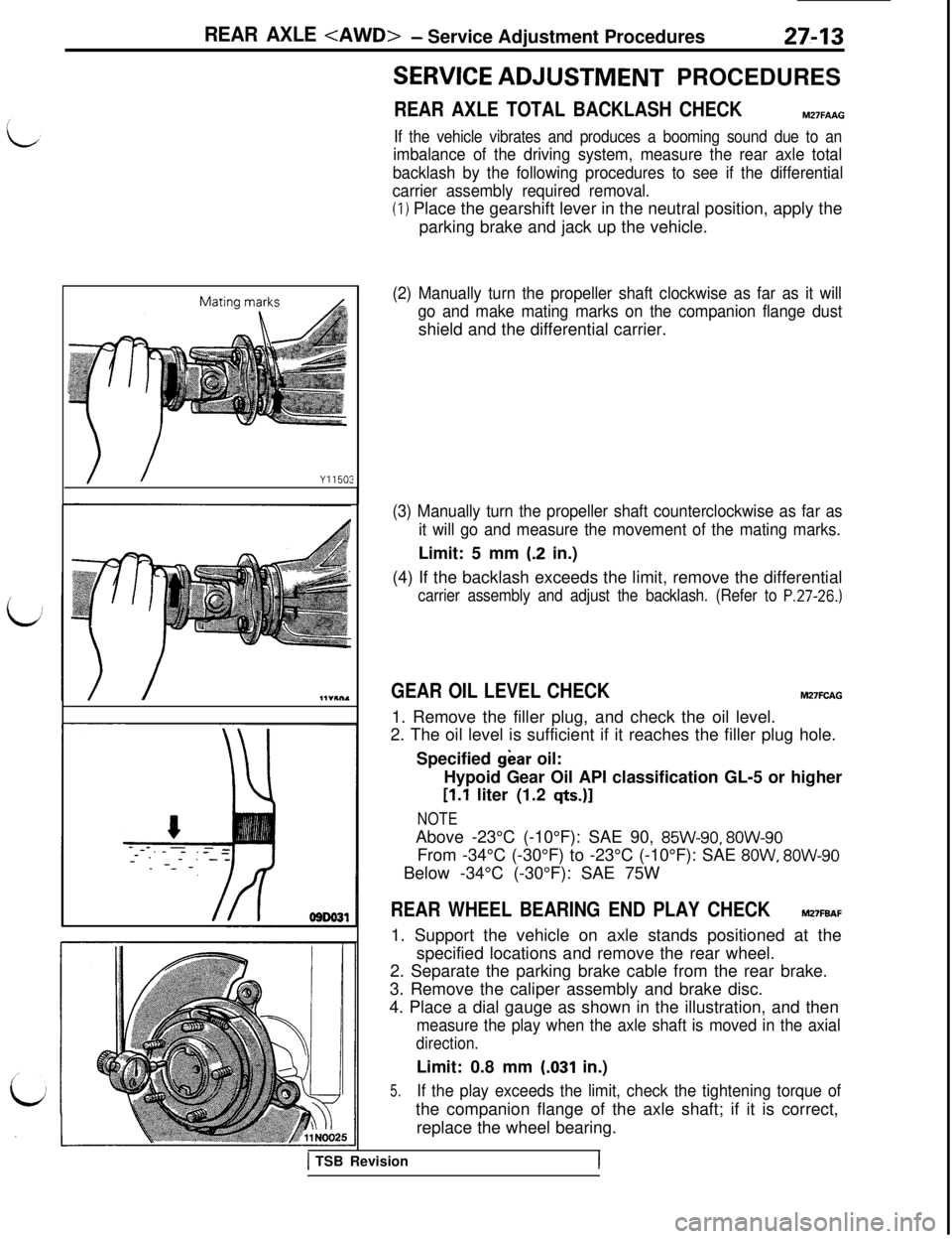
(2) Manually turn the propeller shaft clockwise as far as it will
go and make mating marks on the companion flange dustshield and the differential carrier.
(3) Manually turn the propeller shaft counterclockwise as far as
it will go and measure the movement of the mating marks.Limit: 5 mm
(.2 in.)
(4) If the backlash exceeds the limit, remove the differential
carrier assembly and adjust the backlash. (Refer to P.27-26.)
GEAR OIL LEVEL CHECKM27FCAG1. Remove the filler plug, and check the oil level.
2. The oil level is sufficient if it reaches the filler plug hole.
Specified
gear oil:
Hypoid Gear Oil API classification GL-5 or higher
[l.l liter (1.2 q&J]
NOTEAbove -23°C (-10°F): SAE 90,
85W-90, 8OW-90From -34°C (-30°F) to -23°C (-10°F): SAE
8OW, 8OW-90Below -34°C (-30°F): SAE 75W
REAR WHEEL BEARING END PLAY CHECKM27FBAF1. Support the vehicle on axle stands positioned at the
specified locations and remove the rear wheel.
2. Separate the parking brake cable from the rear brake.
3. Remove the caliper assembly and brake disc.
4. Place a dial gauge as shown in the illustration, and then
measure the play when the axle shaft is moved in the axial
direction.Limit: 0.8 mm
(.031 in.)
5.If the play exceeds the limit, check the tightening torque ofthe companion flange of the axle shaft; if it is correct,
replace the wheel bearing.
1 TSB RevisionI
Page 610 of 1146
27-14REAR AXLE
Incorrect
llA033CREAR WHEEL BEARING ROTATION TORQUE
I
CHECKM27FJAB1. Remove the drive shaft from the companion flange.
2. Remove the brake pad or caliper assembly.
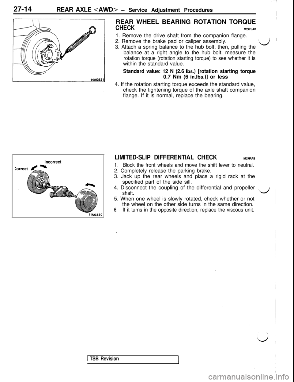
3. Attach a spring balance to the hub bolt, then, pulling the
‘d ’balance at a right angle to the hub bolt, measure the
rotation torque (rotation starting torque) to see whether it iswithin the standard value.
Standard value: 12 N (2.6 Ibs.) [rotation starting torque0.7 Nm (6
in.lbs.)] or less
4. If the rotation starting torque exceeds the standard value,
check the tightening torque of the axle shaft companion
flange. If it is normal, replace the bearing.
LIMITED-SLIP DIFFERENTIAL CHECKM27FlAB
1.Block the front wheels and move the shift lever to neutral.2. Completely release the parking brake.
3. Jack up the rear wheels and place a rigid rack at the
specified part of the side sill.
4. Disconnect the coupling of the differential and propeller
shaft.LJ5. When one wheel is slowly rotated, check whether or not
the wheel on the other side turns in the same direction.
6.If it turns in the opposite direction, replace the viscous unit.
1 TSB Revision
Page 692 of 1146
34-6REAR SUSPENSION
WHEEL BEARING END PLAY INSPECTIONM34FBAG
1.Inspect the play of the bearings while the vehicle is jackedup and resting on floor jack.
2. Remove the hub cap and then release the parking brake.
s&i3. Remove the caliper assembly and the brake disc.
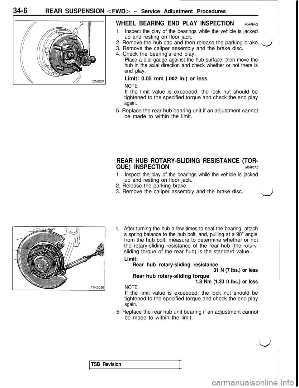
4. Check the bearing’s end play.
Place a dial gauge against the hub surface; then move the
hub in the axial direction and check whether or not there is
end play.Limit: 0.05 mm
(.002 in.) or less
NOTEIf the limit value is exceeded, the lock nut should be
tightened to the specified torque and check the end play
again.5. Replace the rear hub bearing unit if an adjustment cannot
be made to within the limit.
REAR HUB ROTARY-SLIDING RESISTANCE (TOR-
QUE) INSPECTION
M34FCAC
1.Inspect the play of the bearings while the vehicle is jackedup and resting on floor jack.
2. Release the parking brake.
3. Remove the caliper assembly and the brake disc.
..J
4.After turning the hub a few times to seat the bearing, attach
a spring balance to the hub bolt, and, pulling at a 90” anglefrom the hub bolt, measure to determine whether or not
the rotary-sliding resistance of the rear hub (the
rotary-sliding torque of the rear hub) is the standard value.
Limit:
Rear hub rotary-sliding resistance
31 N (7 Ibs.) or lessRear hub rotary-sliding torque
1.8 Nm (1.30 ftlbs.) or less
NOTEIf the limit value is exceeded, the lock nut should be
tightened to the specified torque and check the end play
again.5. Replace the rear hub unit bearing if an adjustment cannot
be made to within the limit.
TSB Revision
Page 693 of 1146
REAR SUSPENSION
REAR SUSPENSION ASSEMBLYM34GA-A
L/
REMOVAL AND INSTALLATION
140- 160 Nm*IOI- 116ftlbs.
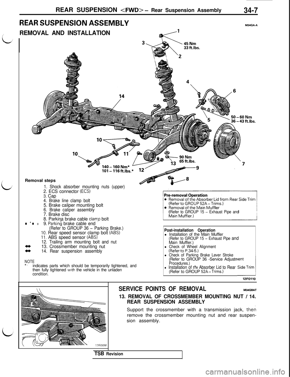
Removal steps
1. Shock absorber mounting nuts (upper)2. ECS connector (ECS)3. Cap4. Brake line clamp bolt5. Brake caliper mounting bolt6. Brake caliper assembly7. Brake disc
8. Parkina brake cable clamo bolt
(Refer to GROUP 15 - Exhaust Pipe and
l * l +9. ParkinG brake cable end ”(Refer to GROUP 36 - Parking Brake.)10. Rear speed sensor clamp bolt (ABS)11. ABS speed sensor (ABS)12. Trailing arm mounting bolt and nut*I)13. Crossmember mounting nut*I)14. Rear suspension assembly
NOTE*.indicates parts which should be temporarily tightened, and
then fully tightened with the vehicle in the unladencondition.
Post-installation Operationl Installation of the Main Muffler(Refer to GROUP 15 - Exhaust Pipe andMain Muffler.)l Check of Wheel Alignment(Refer.to P.34-5.)l Check of Parking Brake Lever Stroke(Refer to GROUP 36 -Service AdjustmentProcedures.)l Installation of the Absorber Lid to Rear Side Trim(Refer to GROUP 52A-Trims.)A12FOllO
SERVICE POINTS OF REMOVALM34GBAT
13. REMOVAL OF CROSSMEMBER MOUNTING NUT / 14.
REAR SUSPENSION ASSEMBLYSupport the crossmember with a transmission jack, then
remove the crossmember mounting nut and rear suspen-
sion assembly.
TSB Revision
Page 697 of 1146
REAR SUSPENSION
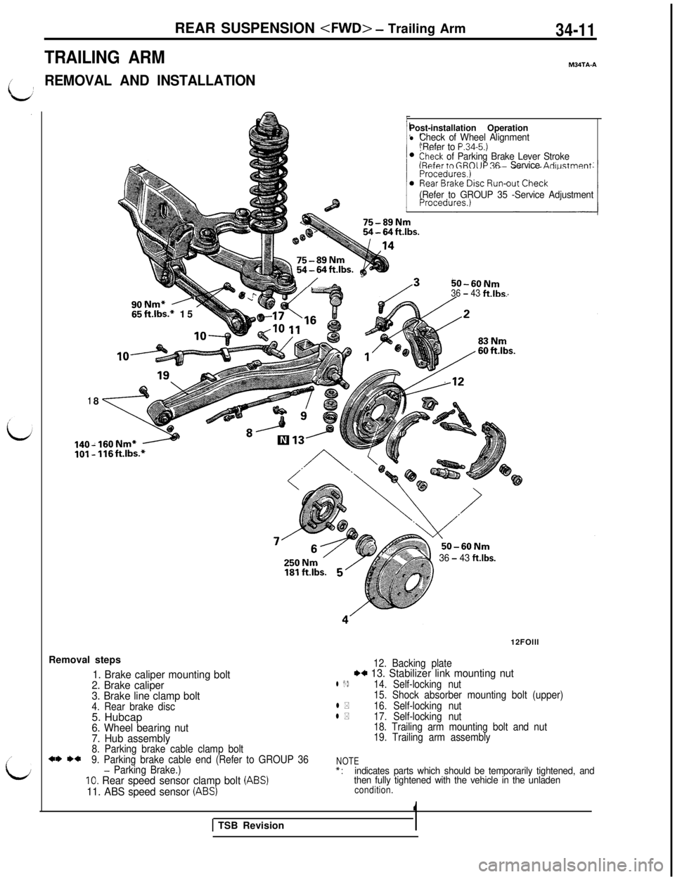
TRAILING ARMM34TA-A
t’REMOVAL AND INSTALLATION
,’
i;
18
90Nm* A65ft.lbs.* 15Post-installation Operation
lCheck of Wheel Alignment
‘Refer to P.34-5.)>heck of Parking Brake Lever Stroke(Refer tn GROIJP 36 - Service Adiustment
r/A -50-60Nm36 - 43ftlbs.
(Refer to GROUP 35 -Service Adjustment
-160Nm* -- 116ft.lbs.*Removal steps
1. Brake caliper mounting bolt
2. Brake caliper
3. Brake line clamp bolt
4. Rear brake disc5. Hubcap
6. Wheel bearing nut
7. Hub assembly
8. Parking brake cable clamp bolt*I) I)*9. Parking brake cable end (Refer to GROUP 36- Parking Brake.)IO. Rear speed sensor clamp bolt (ABS)
11. ABS speed sensor (ABS)
36 - 43 ftlbs.12FOlll
12. Backing plateI)+ 13. Stabilizer link mounting nutl I)14. Self-locking nut
15. Shock absorber mounting bolt (upper)
l *16. Self-locking nutl *17. Self-locking nut
18. Trailing arm mounting bolt and nut
19. Trailing arm assembly
NOTE*:indicates parts which should be temporarily tightened, and
then fully tightened with the vehicle in the unladen
condition.
1 TSB Revision1
Page 710 of 1146
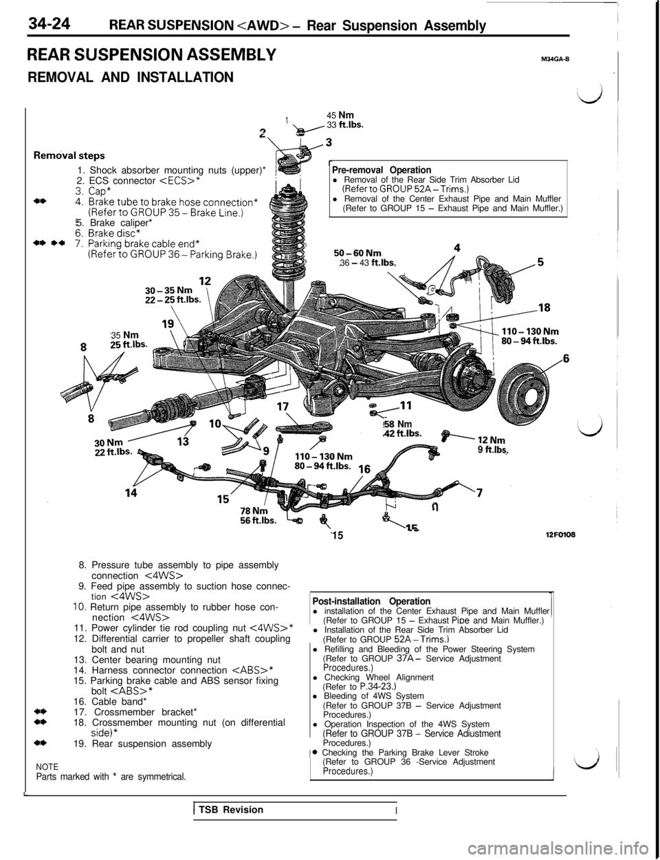
34-24REAR SUSPENSION
REAR SUSPENSION ASSEMBLY
REMOVAL AND INSTALLATION
M34GA-B
L
Rel
145 Nm9- 33 ftlbs.
1. Shock absorber mounting nuts (upper)*
2. ECS connector
(RefertoGROUP52A-Trims.)l Removal of the Center Exhaust Pipe and Main Muffler
(Refer to GROUP 15
- Exhaust Pipe and Main Muffler.)
5. Brake caliper*
1,50-60NmI36 - 43 ft.lbs.35 Nm
$8 Nm“?C,ILc. ashwez I,..“=.BP’----12Nm9 ftlbs.
15..e12FO1088. Pressure tube assembly to pipe assembly
connection
<4WS>9. Feed pipe assembly to suction hose connec-
tion
<4WS>10. Return pipe assembly to rubber hose con-
nection t4WS>11. Power cylinder tie rod coupling nut <4WS>*12. Differential carrier to propeller shaft coupling
bolt and nut
Post-installation Operationl installation of the Center Exhaust Pipe and Main Muffler
(Refer to GROUP 15
- Exhaust Pioe and Main Muffler.)
l Installation of the Rear Side Trim Absorber Lid
(Refer to GROUP
52A-Trims.)13. Center bearing mounting nut
14. Harness connector connection
CABS>*15. Parking brake cable and ABS sensor fixingl Refilling and Bleeding of the Power Steering System
(Refer to GROUP
37A- Service AdjustmentProcedures.)bolt
17. Crossmember bracket*
18. Crossmember mounting nut (on differential
side)”19. Rear suspension assemblyl Checking Wheel Alignment
(Refer to P.34-23.)
l Bleeding of 4WS System
(Refer to GROUP 37B
- Service Adjustment
Procedures.)
l Operation Inspection of the 4WS System
(Refer to GROUP 37B - Service AdiustmentProcedures.)
NOTEParts marked with * are symmetrical.
,* Checking the Parking Brake Lever Stroke
(Refer to GROUP 36 -Service Adjustment
Procedures.)i
1 TSB RevisionI
Page 716 of 1146
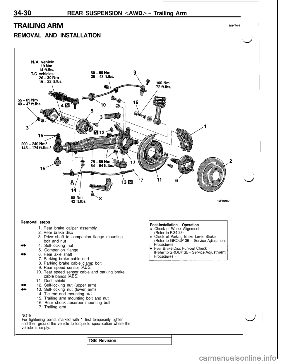
34-30REAR SUSPENSION
TRAILING ARMM34TA-B1
REMOVAL AND INSTALLATIONN/A
$icJ
14 ft.lbs.T/C vehicles26-30Nm
50-60Nm936 - 43 ftlbs.\19 - 22 ft.lbs.
55-65Nm40 - 47ft.lbs.
200
- 240 Nm*145- 174ft.lbs.* I
P100 Nm
72 ft.lbs.
58 Nm’ <842 ft.lbs.Removal steps
*I)
*I)
+*+*
1. Rear brake caliper assembly
2. Rear brake disc
3. Drive shaft to companion flange mounting
bolt and nut
4. Self-locking nut
5. Companion flange
6. Rear axle shaft
7. Parking brake cable end
8. Parking brake cable clamp bolt
9. Rear speed sensor
(ABS)IO. Rear speed sensor cable and parking brake
cable bands (ABS)II. Dust shield
12. Self-locking nut (upper arm)
13. Self-locking nut (lower arm)
14. Tie rod end mounting
nut15. Trailing arm mounting bolt and nut
16. Rear shock absorber mounting bolt
17. Trailing arm
NOTEFor tightening points marked with *, first temporarily tighten
and then ground the vehicle to torque to specification where the
vehicle is empty.‘7
il 6’
12FOO89
Post-installation Operationl Check of Wheel Alignment
(Refer to P.34-23)l Check of Parking Brake Lever Stroke(Refer to GROUP 36 - Service Adiustment
TSB Revision
Page 720 of 1146
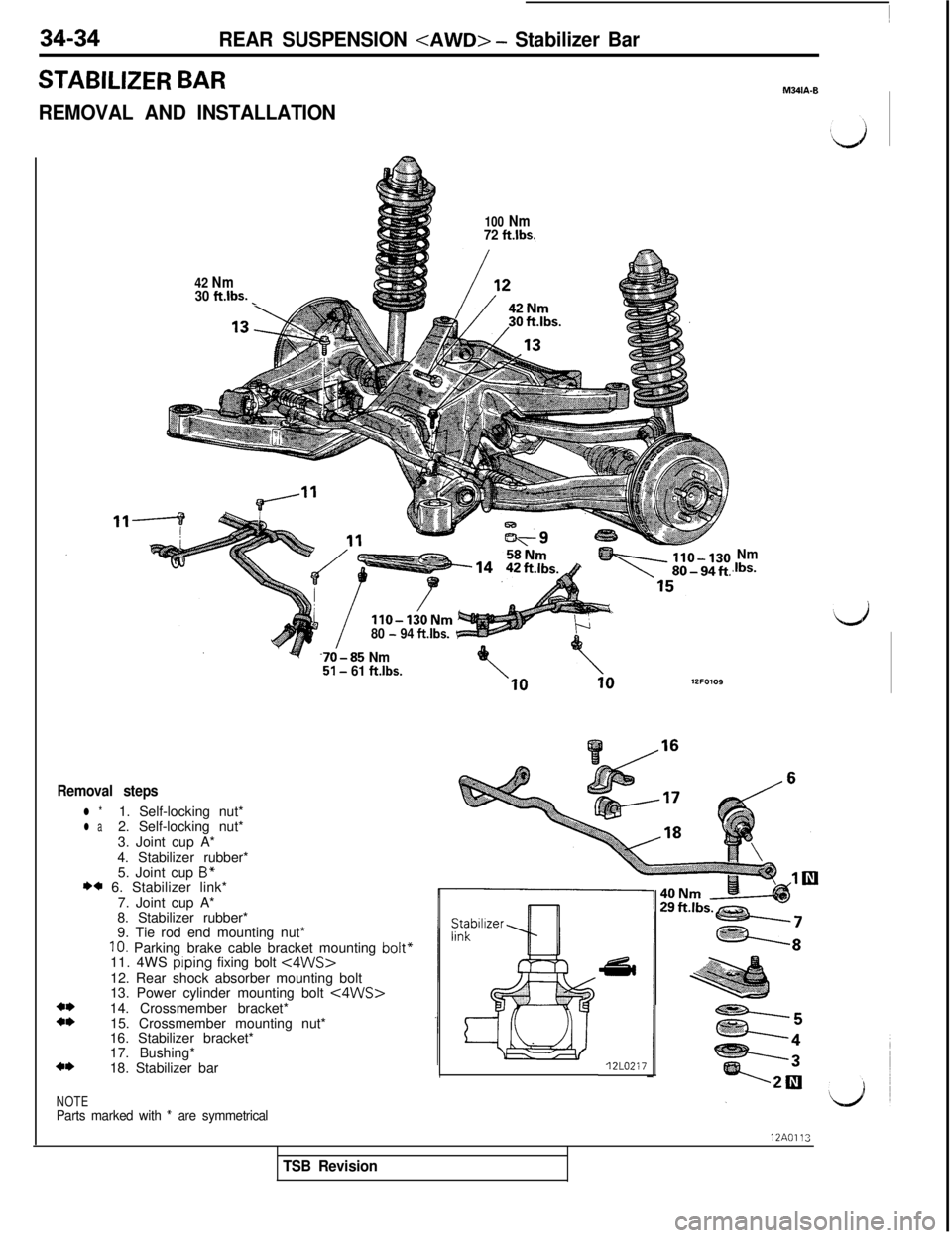
34-34REAR SUSPENSION
STABILIZER BAR
REMOVAL AND INSTALLATION
100 Nm72 ft.lbs.
42 Nm4
30 ft.lbs._
/IIO-130Nm80 - 94 ftlbs.
70-85 Nm51- 61 ftlbs.
Removal steps
l *1. Self-locking nut*l a2. Self-locking nut*
3. Joint cup A*
4. Stabilizer rubber*
5. Joint cup
B”I)* 6. Stabilizer link*
7. Joint cup A*
8. Stabilizer rubber*
9. Tie rod end mounting nut*
IO. Parking brake cable bracket mounting bolt”11. 4WS prping fixing bolt <4WS>12. Rear shock absorber mounting bolt
13. Power cylinder mounting bolt
<4WS>14. Crossmember bracket*
15. Crossmember mounting nut*
16. Stabilizer bracket*
17. Bushing*
18. Stabilizer bar
NOTEParts marked with * are symmetrical12L0217
Nm.Ibs.
M341A.B12A0113
TSB Revision
Page 728 of 1146
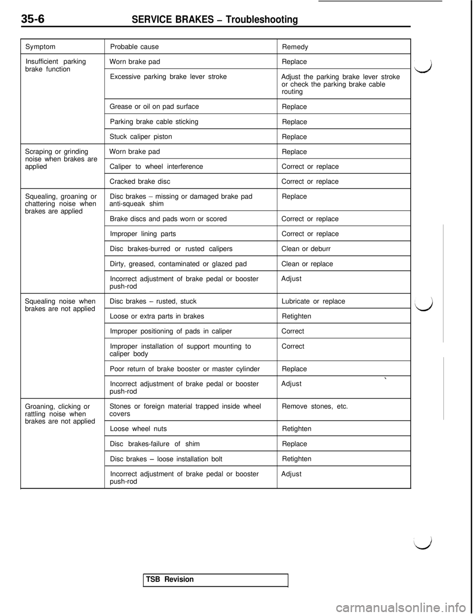
35-6SERVICE BRAKES - TroubleshootingSymptomProbable cause
Remedy
Insufficient parking
Worn brake pad
brake functionReplace
Excessive parking brake lever stroke
Adjust the parking brake lever stroke
or check the parking brake cable
routing
Grease or oil on pad surface
Replace
Parking brake cable sticking
Replace
Stuck caliper piston
Replace
Scraping or grindingWorn brake pad
noise when brakes areReplace
appliedCaliper to wheel interferenceCorrect or replace
Cracked brake discCorrect or replace
Squealing, groaning or
chattering noise whenDisc brakes
- missing or damaged brake pad
anti-squeak shimReplace
brakes are applied
Brake discs and pads worn or scoredCorrect or replace
Improper lining partsCorrect or replace
Disc brakes-burred or rusted calipersClean or deburr
Dirty, greased, contaminated or glazed padClean or replace
Incorrect adjustment of brake pedal or booster
push-rodAdjust
Squealing noise whenDisc brakes
- rusted, stuck
brakes are not appliedLubricate or replace
Loose or extra parts in brakesRetighten
Improper positioning of pads in caliperCorrect
Improper installation of support mounting toCorrect
caliper body
Poor return of brake booster or master cylinderReplace
Incorrect adjustment of brake pedal or booster
push-rodAdjust
Groaning, clicking orStones or foreign material trapped inside wheelRemove stones, etc.
rattling noise whencovers
brakes are not applied
Loose wheel nutsRetighten
Disc brakes-failure of shimReplace
Disc brakes
- loose installation boltRetighten
Incorrect adjustment of brake pedal or booster
push-rodAdjust
TSB Revision
d
d
Page 775 of 1146
L.
SERVICE BRAKES -Service Adjustment Procedures35-53
I14A0398
14F003r
i14A04014NOO27
7
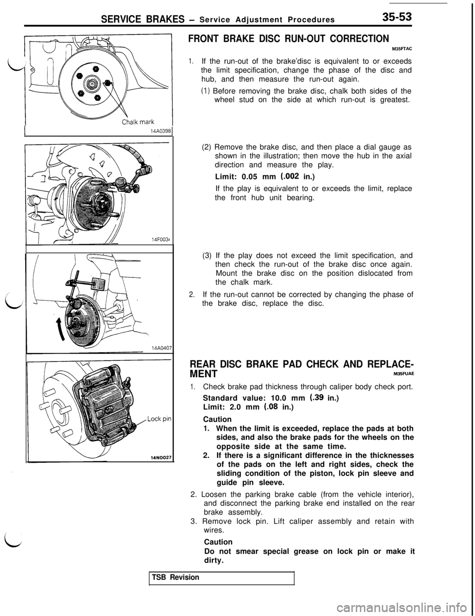
FRONT BRAKE DISC RUN-OUT CORRECTION
M35FFAC
1.If the run-out of the brake’disc is equivalent to or exceeds
the limit specification, change the phase of the disc and
hub, and then measure the run-out again.
(1) Before removing the brake disc, chalk both sides of the
wheel stud on the side at which run-out is greatest.
(2) Remove the brake disc, and then place a dial gauge as
shown in the illustration; then move the hub in the axial
direction and measure the play.
Limit: 0.05 mm (.002 in.)
If the play is equivalent to or exceeds the limit, replace
the front hub unit bearing.
(3) If the play does not exceed the limit specification, and
then check the run-out of the brake disc once again.
Mount the brake disc on the position dislocated from
the chalk mark.
2.If the run-out cannot be corrected by changing the phase of
the brake disc, replace the disc.
REAR DISC BRAKE PAD CHECK AND REPLACE-
MENTM35FUAE
1.Check brake pad thickness through caliper body check port.
Standard value: 10.0 mm
(39 in.)
Limit: 2.0 mm
(08 in.)
Caution
1.When the limit is exceeded, replace the pads at both
sides, and also the brake pads for the wheels on the
opposite side at the same time.
2.If there is a significant difference in the thicknesses
of the pads on the left and right sides, check the
sliding condition of the piston, lock pin sleeve and
guide pin sleeve.
2. Loosen the parking brake cable (from the vehicle interior),
and disconnect the parking brake end installed on the rear
brake assembly.
3. Remove lock pin. Lift caliper assembly and retain with
wires.
Caution
Do not smear special grease on lock pin or make it
dirty.
TSB Revision