MITSUBISHI 3000GT 1991 Service Manual
Manufacturer: MITSUBISHI, Model Year: 1991, Model line: 3000GT, Model: MITSUBISHI 3000GT 1991Pages: 1146, PDF Size: 76.68 MB
Page 1 of 1146
Volume lm
I ‘k,‘6III
Engine, Chassis & Bodyf
Page 2 of 1146

Page 3 of 1146
d
L’ BackupServiceManual
3OOOG-r
1991: Volume 1
L
This Service Manual has been prepared with the
/
WE SUPPORT
I/National ,nwtute ‘or IIAUTOMOTIV E
/I
MITSUBISHI
li@ 1990 Mitsubishi Motors CorporationRqwinted in USA
I
General
..*............*......*.......................
Su;$emental Restraint System ....
*......*...........
I
NOTE:I
I I
Page 4 of 1146
SUPPLEMENTAL RESTRAINT SYSTEM (SRS)
dir J
bag module, clock spring, interconnecting wiring. Other SRS-related comp\
onents (that may have to be
(*).
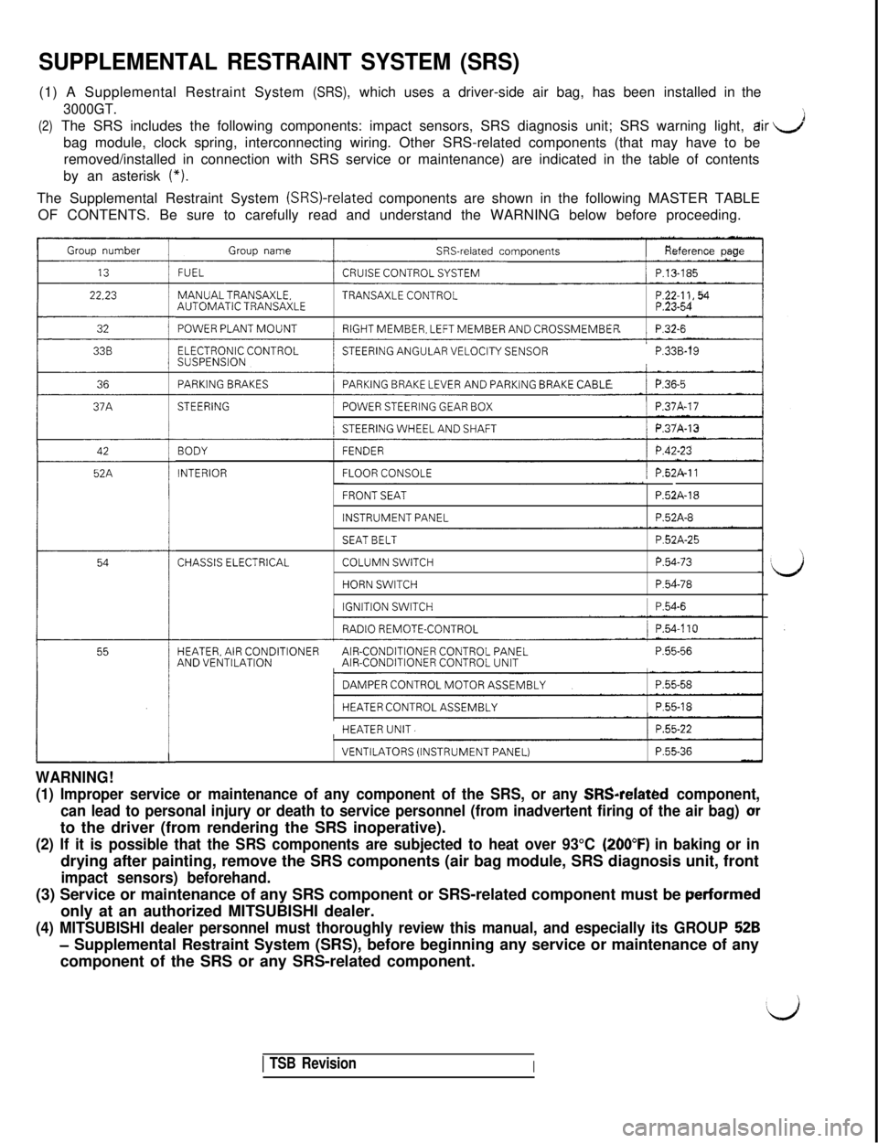
The Supplemental Restraint System (SRSI-related components are shown in the following MASTER TABLE
OF CONTENTS. Be sure to carefully read and understand the WARNING below \
before proceeding.
Group number
22.23
32
36
42
52A
Group nameSRS-related components
FUELCRUISE CONTROL SYSTEM/ P.13-185
MANUALTRANSAXLE.TRANSAXLE CONTROLAUTOMATIC TRANSAXLE
POWER PLANT MOUNTRIGHT MEMBER, LEFT MEMBER AND CROSSMEMBERP.32-6
ELECTRONIC CONTROLSUSPENSION’STEERING ANGULAR VELOCITY SENSORP.33B-19
PARKING BRAKESPARKING BRAKE LEVER AND PARKiNG BRAKE CABLE/ P.36~5I
STEERING/POWER STEERING GEAR BOX/ P.37A-17
/STEERING WHEEL AND SHAFTj P.37A-13
BODY
INTERIOR
FENDER
FLOOR CONSOLE/ P.52A-11
FRONT SEAT
INSTRUMENT PANEL
P52A-18
P.52A-8
CHASSIS ELECTRICAL
SEAT BELT
COLUMN SWITCH
HORN SWITCH
IGNITION SWITCH
P.52A-25
P.54-73
P.54-78
1 P.54-6
RADIO REMOTE-CONTROL/ P.54.110
HEATER, AIR CONDITIONERAIR-CONDITIONER CONTROL PANELAND VENTILATIONAIR-CONDITIONER CONTROL UNITP.55-56
/DAMPER CONTROL MOTOR ASSEMBLYI
/HEATER CONTROL ASSEMBLY1 P.55-18I
HEATER UNIT.1 P.55-22
WARNING!
VENTILATORS (INSTRUMENT PANEL)P.55-36
(1) Improper service or maintenance of any component of the SRS, or an\
y SRSrelated component,
can lead to personal injury or death to service personnel (from inadver\
tent firing of the air bag) or
to the driver (from rendering the SRS inoperative).
(260°F) in baking or in
drying after painting, remove the SRS components (air bag module, SRS d\
iagnosis unit, front
perfarmed
only at an authorized MITSUBISHI dealer.
52B
- Supplemental Restraint System (SRS), before beginning any service or m\
aintenance of any
component of the SRS or any SRS-related component.
1 TSB RevisionI
Page 5 of 1146
,
b
00-I
GENERALCONTENTS
MOOOA- .
GENERAL DATA AND SPECIFICATIONS . . . . . .21
HOW TO USE THIS MANUAL. . . . . . . . . . . . . . . . . . . . . . . . . . . .3Definition of Terms
. . . . . . . . . . . . . . . . . . . . . . . . . . . . . . . . . . . . . . . . . . . .3Explanation of Circuit Diagrams
. . . . . .._...........7Explanation of Manual Contents
. . . . . . . . . . . . . . . . . . . .4
Explanation of the Troubleshooting Guide . .
6ModelIndications
. . . . . . . . . . . . . . . . . . . . . . . . . . . . . . . . . . . . . . . . . . . .3Scope of Maintenance, Repair and
ServicingExplanations
. . . . . . . . . . . . . . . . . . . . . . . . . . . . . . . . . . . .3Troubleshooting
. . . . . . .._.......................................3
LUBRICATION AND MAINTENANCE. . . . . .._....31SCHEDULED MAINTENANCE TABLE. . . . . . .._.
MAIN SEALANT AND ADHESIVE TABLE. . .44
MAINTENANCE SERVICE
. . . . . . . . . . . . . . . .._......_.....__Air Cleaner Element
. . . . . . .._......._......_................Automatic Transaxle
. . . . . . . . . . . . . . . . . . . . . . . . .._......._.....Ball Joint and Steering Linkage Seals
. . . . . . . . . . . .
BrakeHoses. . . . . . . . . . . . . . . . . . . . . . . . . . . .._......._.._...._......._..
Disc Brake Pads. . . . . . . . . . . . . . . . . . . . . . . . . . . . . . . . . . . . . . . . . . . . . . . .Drive Belt (For Alternator)
. . . . . . . . .._.........._..........Drive Shaft Boots
. . . . . . . . . . . . . . . . . . . . . . . . . . . . . . . . . . . .Engine Coolant
. . . . . . . . . . . . ..__.._.............................Engine Oil
.._....__._.................................................Engine Oil Filter
. . . . .._._.......__.................. . . . . . . . . . . .Exhaust System
_....._......._.....__._............,...........Fuel Hoses
..__......__............................................36
3740
42
42
42
38
43
41
38
39
43
36
FuelSystem. . . . . . . . . . . . . . . . . . . . . . . . . . . . . . . . . . . . . . . . . . . . . . . . . . . . . . . .Manual Transaxle
. . . . . . . . . .._........................_.......Rear Axle
. . . . . . . . . . . . . . . . . . . . . . . . . . . . . . . . . . .._..._.._..____.._.......
SparkPlugs. . . . . . . . . . . . . . . . . . . . . . . . . . . . . . . . . . . . . . .._...............TimingBelt
. . . . . . . . . . . . . . . . . . . . . . . . . . . . . . . . . . . . . . . . . . . . . . . . . . . . . . . .
MASTER TROUBLESHOOTING. . . . . . . . . . . . . . . . . . . . . . . .
PRECAUTIONS BEFORE SERVICE. . . . . . . . . . . . . . . .
RECOMMENDED LUBRICANTS AND
LUBRICANT CAPACITIES TABLE. . . . . . .._........
SPECIAL HANDLING INSTRUCTIONS
FOR AWD MODELS. . . . . . . . . . . . .._...._........................
TIGHTENING TORQUE. . . . . . . . . . . . . . . ..__.....................
TOWING AND HOISTING. . . . . . . . . . . . . . . . . . . . . . . . . . . . . . . .
VEHICLE IDENTIFICATION. . . . . . . . . . . . . . . . . . . . . . . . .._.....Chassis Number .
.._............................................Engine Model Stamping
.._..........................._...._Theft Protection
. . . . .._.........................................Vehicle Identification Code Chart Plate
.._.....Vehicle Identification Number List
.._._....._..._.Vehicle Identification Number Location
. . . .._
Vehicle Information Code Plate . . . . .._._......_.......Vehicle Safety Certification Label
. . . ..I . . . . .._..._...
36
3943
37
3724
1532
35
20
23
16
8
10
11
11
8
9
8
10
10
Page 6 of 1146
c.
Page 7 of 1146
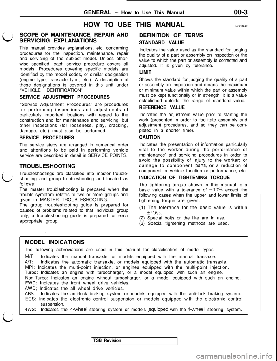
GENERAL - How to Use This Manual00-3HOW TO USE THIS MANUAL
MOOBAAF
c;SCOPE OF MAINTENANCE, REPAIR AND
DEFINITION OF TERMS
SERVICING EXPLANATIONSSTANDARD VALUE
bThis manual provides explanations, etc. concerning
procedures for the inspection, maintenance, repair
and servicing of the subject model. Unless other-
wise specified, each service procedure covers all
models. Procedures covering specific models are
identified by the model codes, or similar designation
(engine type, transaxle type, etc.). A description of
these designations is covered in this unit under
“VEHICLE IDENTIFICATION”.
SERVICE ADJUSTMENT PROCEDURES“Service Adjustment Procedures” are procedures
for performing inspections and adjustments of
particularly important locations with regard to the
construction and for maintenance and servicing, but
other inspections (for looseness, play, cracking,
damage, etc.) must also be performed.
SERVICE PROCEDURESThe service steps are arranged in numerical order
and attentions to be paid in performing vehicle
service are described in detail in SERVICE POINTS.
TROUBLESHOOTING
Troubleshootings are classified into master trouble-
shooting and group troubleshooting and located as
follows:
The master troubleshooting is prepared when the
trouble symptom relates to two or more groups and
given in MASTER TROUBLESHOOTING.
The group troubleshooting guide is prepared for
causes of problems related to that individual groupIndicates the value used as the standard for judging
the quality of a part or assembly on inspection or the
value to which the part or assembly is corrected and
adjusted. It is given by tolerance.
LIMITShows the standard for judging the quality of a part
or assembly on inspection and means the maximum
or minimum value within which the part or assembly
must be kept functionally or in strength. It is a value
established outside the range of standard value.
REFERENCE VALUEIndicates the adjustment value prior to starting the
work (presented in order to facilitate assembly and
adjustment procedures, and so they can be com-
pleted in a shorter time).
CAUTIONIndicates the presentation of information particularly
vital to the worker during the performance of
maintenance’ and servicing procedures in order to
avoid the possibility of injury to the worker; or
damage to component
.parts, or a reduction of
component or vehicle function or performance, etc.
INDICATION OF TIGHTENING TORQUEThe tightening torque shown in this manual is a
basic value with a tolerance of
+lO% except the
following cases when the upper and lower limits of
tightening torque are given.
(1) The tolerance for the basic value is within
+ I no/-
only; a troubleshooting guide is prepared for eachI iv,“.appropriate group.(2) Special bolts or the like are in use.
(3) Special tighteningmethods are used.
MODEL INDICATIONS
The following abbreviations are used in this manual for classification of model types.M/T:Indicates the manual transaxle, or models equipped with the manual transaxle.
A/T:Indicates the automatic transaxle, or models equipped with the automatic transaxle.
MPI: Indicates the multi-point injection, or engines equipped with the multi-point injection.
Turbo: Indicates an engine with turbocharger, or a model equipped with such an engine.
Non-Turbo: Indicates an engine without turbocharger, or a model equipped with such an engine.
FWD: Indicates the front wheel drive vehicles.
AWD; Indicates the all wheel drive vehicles.
ABS:Indicates the anti-lock braking system or models equipped with the anti-lock braking system.
ECS: Indicates the electronic control suspension or models equipped with the electronic control
suspension.
4WS:Indicates the 4-wheel steering system or models .equipped with the 4-wheel steering system.
TSB Revision
Page 8 of 1146
GENERAL - How to Use This Manual
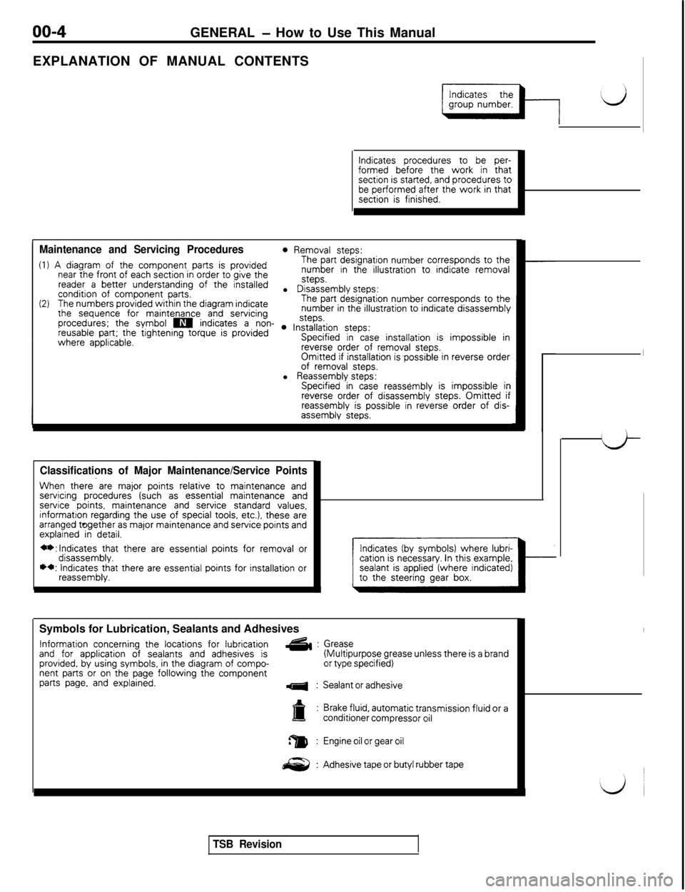
EXPLANATION OF MANUAL CONTENTS
Indicates procedures to be per-formed before the work in thatsection is started, and procedures tobe performed after the work in thatsection is finished.
Maintenance and Servicing Procedures0 Removal steps:
(1) A diagram of the component parts is providedThe part designation number corresponds to the
near the front of each section in order to give thenumber in the illustration to indicate removal
reader a better understanding of the installedsteps.
condition of component parts.l Disassembly steps:
(2)The numbers provided within the diagram indicateThe part designation number corresponds to the
the sequence for maintenance and servicingnumber in the illustration to indicate disassembly
procedures; the symbol m indicates a non- . ln~~~~iion steps:reusable part; the tightening torque is providedwhere applicable.Specified in case installation is impossible inreverse order of removal steps.Omitted if installation is,possible in reverse orderof removal steps.l Reassembly steps:Specified in case reassembly is impossible inreverse order of disassembly steps. Omitted ifreassembly is possible in reverse order of dis-assembly steps.
Classifications of Major Maintenance/Service Points
When there’are major points relative to maintenance andservicing procedures (such as essential maintenance andservice points, maintenance and service standard values,informatton regarding the use of special toois, etc.), these arearranged together as major maintenance and service points andexplained in detail.
**:lndicates that there are essential points for removal ordisassembly.*+: Indicates that there are essential points for installation orreassembly.Symbols for Lubrication, Sealants and Adhesives
Information concerning the locations for lubricationand for application of sealants and adhesives isG&:
provided, by using symbols, in the diagram of compo-nent parts or on the page following the componentparts page, and explained.4:
Indicates (by symbols) where lubri-cation is necessary. In this example,
Grease(Multipurpose grease unless there is a brandor type specified)
Sealant or adhesive
Brake fluid, automatic transmission fluid or aconditioner compressor oil
Engine oil or gear oil
Adhesive tape or butyl rubber tape
TSB Revision
Page 9 of 1146
GENERAL - How to Use This Manual00-5
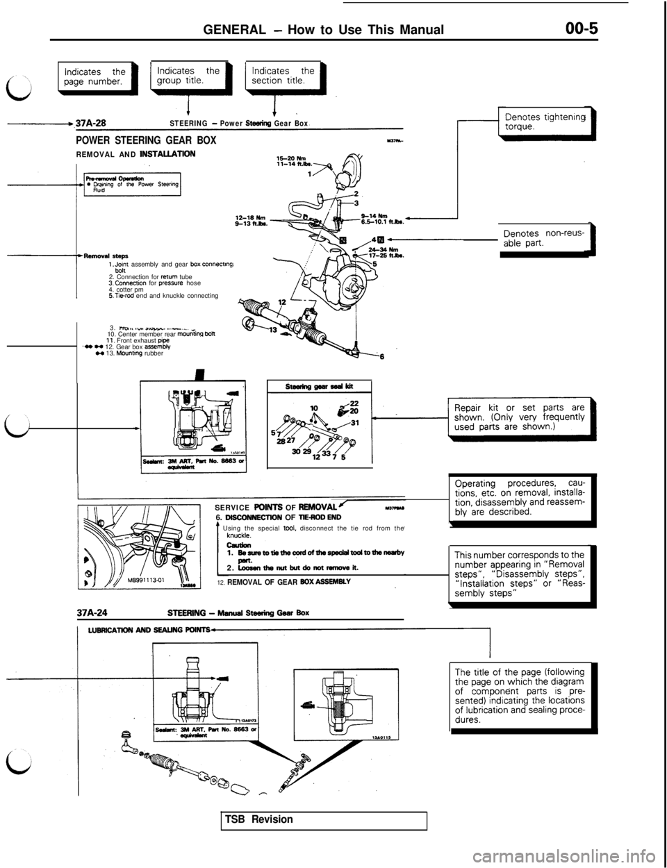
Indicates thepage number.
\
-.37A-28STEERING - Power Steering Gear Box
POWER STEERING GEAR BOX
REMOVAL AND INSTAUATION1!3-20 Plm
-7-Renloval steps
1 .Jrnyt assembly and gear box connecting2. Connection for
return tube3.Connection for press.ure hose
4. cotter pm
5.T1erod end and knuckle connecting
3.
maI,% ,v*, ,tu&w.,. *.-._10. Center member rear mourha WR11, Front exhaust pipe‘0 w 12. Gear box assembly” 13. Mountmg rubber
Denotes tightenrng
Denotes non-reus-able part.
SERVICE POINTS OF REMOVALJ-Y-6. Ol6CONN6CTtON OF TIE-ROD END* Using the special tool, disconnect the tie rod from the
Operating procedures, cau-tions, etc. on removal, installa-tion, disassembly and reassem-bly are described.
\
37A-24
1.60sumtotie6lec?rdofthaspecialwJdtotheneflrbY2.
~thsmItbutdonDt-vsit.
12. REMOVAL OF GEAR 60X ASSEMBLY
STEERING - Manual Steering Gwr Box
This number corresponds to thenumber appearing in “Removalsteps”,“Disassembly steps”,“installation steps” or “Reas-sembly steps”
\
The title of the page (followingthe page on which the diagramof component parts is pre-sented) indicating the locationsof lubrication and sealing proce-dures.
TSB Revision
Page 10 of 1146
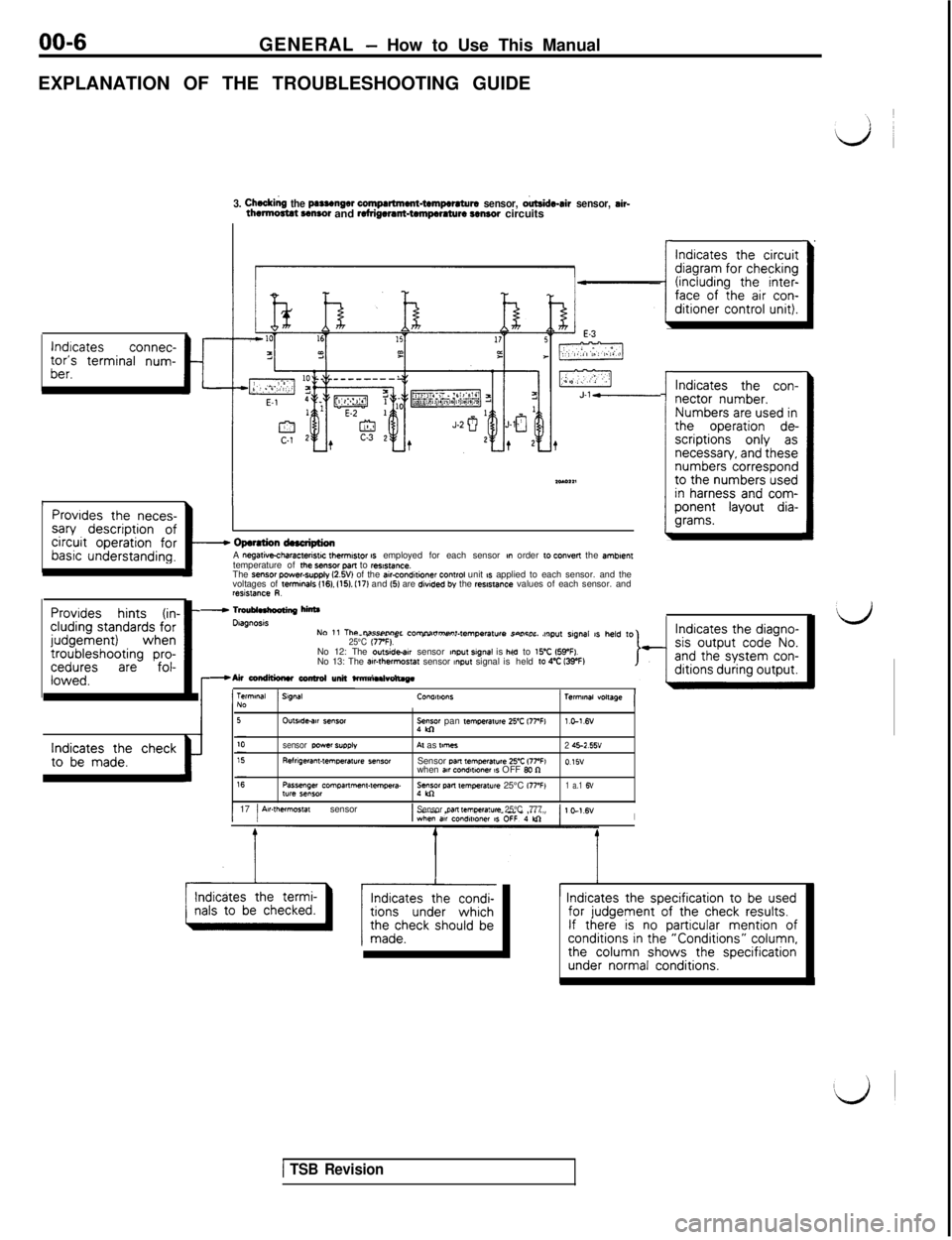
00-6
GENERAL - How to Use This Manual
EXPLANATION OF THE TROUBLESHOOTING GUIDE
lndrcatesconnec-tor’s terminal num-ber.t
3. Cheddng the psssenger compartment-tempwsturs sensor, o&de-sir sensor, sir-thwtmctat CMSO~ and refrigerant-tempcmture sensor circuits
1.IProvides the neces-sary description ofcircuit operation forbasic understanding.I
Provides hints (in- -eluding standards forjudgement)whentroubleshooting pro-ceduresarefol-lowed.
- Opsrstion dnctiptionA negatkcharactensw fhemwor IS employed for each sensor nn order 10 convert the smbnen,temperature of rhe SB”SOf pan to ,es,s,ance.The sensor power-supply l2.W) of the air-condaioner control unit 1s applied to each sensor. and the
voltages of terminals 1161. 1151. I171 and 15) are divtded by the rwstance values of each sensor. andresislance R.
Indicates the checkto be made.t
-
I
Indicates the circuitdiagram for checking(including the inter-face of the air con-ditioner control unit).
Indicates the con-nector number.Numbers are used inthe operation de-scriptions only asnecessary, and thesenumbers correspondto the numbers usedin harness and com-ponent layout dia-grams.
- Tmublnkooting hff
NO 1, The DilFW+““P, P”m”il”m~“l.l~m~~=,,,,~ concnr ,w,p”t s,g”a, ,s ,,e,d ,o_ -____ .=_ __ .~_. .._... ._...r_._._._ ” -..--. ..,25°C 17rF).No 12: The outside-w sensor mput srgnal is he.----la to ,,“C IWFI.
-Air conditiuw ccnlml unit ta-.--* -.. No 13: The
awthwmos,a, sensor ~npu, signal isheld 10 4% IWF)l?mlMI “obuge
^I_I1Terminal) SWAW”IIWO”SNO
Dtagnosls
OUlYdedlr semorye pan ,emperatwe 25’C l77Wl.c-1.6v
sensor wwsr
SUPPI”Al as ,mlles2 45-2.55vRelngeran,.,emwrature *ensorSensor WR temperawe 25-Z 17PFI015”
when aar condwmer 1s OFF Bo nPassenger Compa*me”,-tempera.:“gol pm mnperat”re 25°C i77’FI1 a.1 6”lyre sensor
1 17 j Air-thermostat sensor1Sensor pan ,empelat”re 25°C ,777,I
’ Indicates the specification to be usedfor judgement of the check results.If there is no particular mention ofconditions in the “Conditions” column,the column shows the specificationunder normal conditions.
I
I
1 TSB Revision