seat adjustment MITSUBISHI 3000GT 1991 Service Manual
[x] Cancel search | Manufacturer: MITSUBISHI, Model Year: 1991, Model line: 3000GT, Model: MITSUBISHI 3000GT 1991Pages: 1146, PDF Size: 76.68 MB
Page 65 of 1146
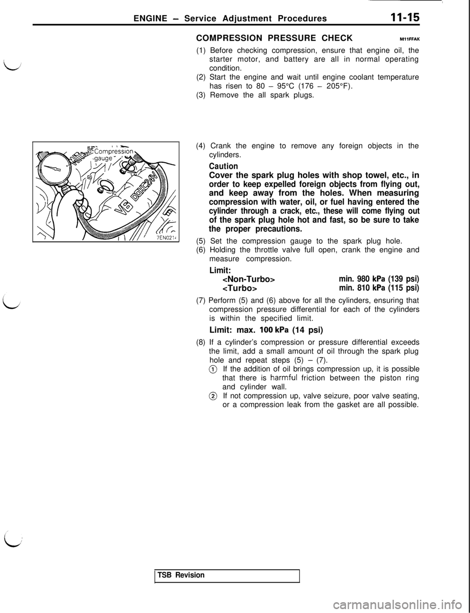
ENGINE - Service Adjustment Procedures11-15COMPRESSION PRESSURE CHECKMllFFAK
(1) Before checking compression, ensure that engine oil, the
starter motor, and battery are all in normal operating
condition.
(2) Start the engine and wait until engine coolant temperature
has risen to 80
- 95°C (176 - 205°F).
(3) Remove the all spark plugs.
(4) Crank the engine to remove any foreign objects in the
cylinders.
CautionCover the spark plug holes with shop towel, etc., in
order to keep expelled foreign objects from flying out,and keep away from the holes. When measuring
compression with water, oil, or fuel having entered the
cylinder through a crack, etc., these will come flying out
of the spark plug hole hot and fast, so be sure to take
the proper precautions.(5) Set the compression gauge to the spark plug hole.
(6) Holding the throttle valve full open, crank the engine and
measure compression.
Limit:
min. 980 kPa (139 psi)
min. 810 kPa (115 psi)(7) Perform (5) and (6) above for all the cylinders, ensuring that
compression pressure differential for each of the cylinders
is within the specified limit.
Limit: max.
100 kPa (14 psi)
(8) If a cylinder’s compression or pressure differential exceeds
the limit, add a small amount of oil through the spark plug
hole and repeat steps (5)
- (7).@If the addition of oil brings compression up, it is possible
that there is
harmf,uI friction between the piston ring
and cylinder wall.@If not compression up, valve seizure, poor valve seating,
or a compression leak from the gasket are all possible.
TSB Revision
Page 316 of 1146
15-6INTAKE AND EXHAUST - Service Adjustment Procedures
Variable rnductiorcontrol servoconnectors
6FU1277
Open
Close
71 NO105
SERVICE ADJUSTMENT PROCEDURESMlSGlAA
VARIABLE INDUCTION CONTROL SYSTEM IN-
d
SPECTION (Non Turbo)
SYSTEM INSPECTION
(1) Warm up the engine.
(2) Connect the tachometer. (Refer to GROUP 11 - Engine
Adjustment.)
(3) Make sure that when the engine speed is increased from
the idle speed to 5,000 rpm, the induction control valve
shaft turns.
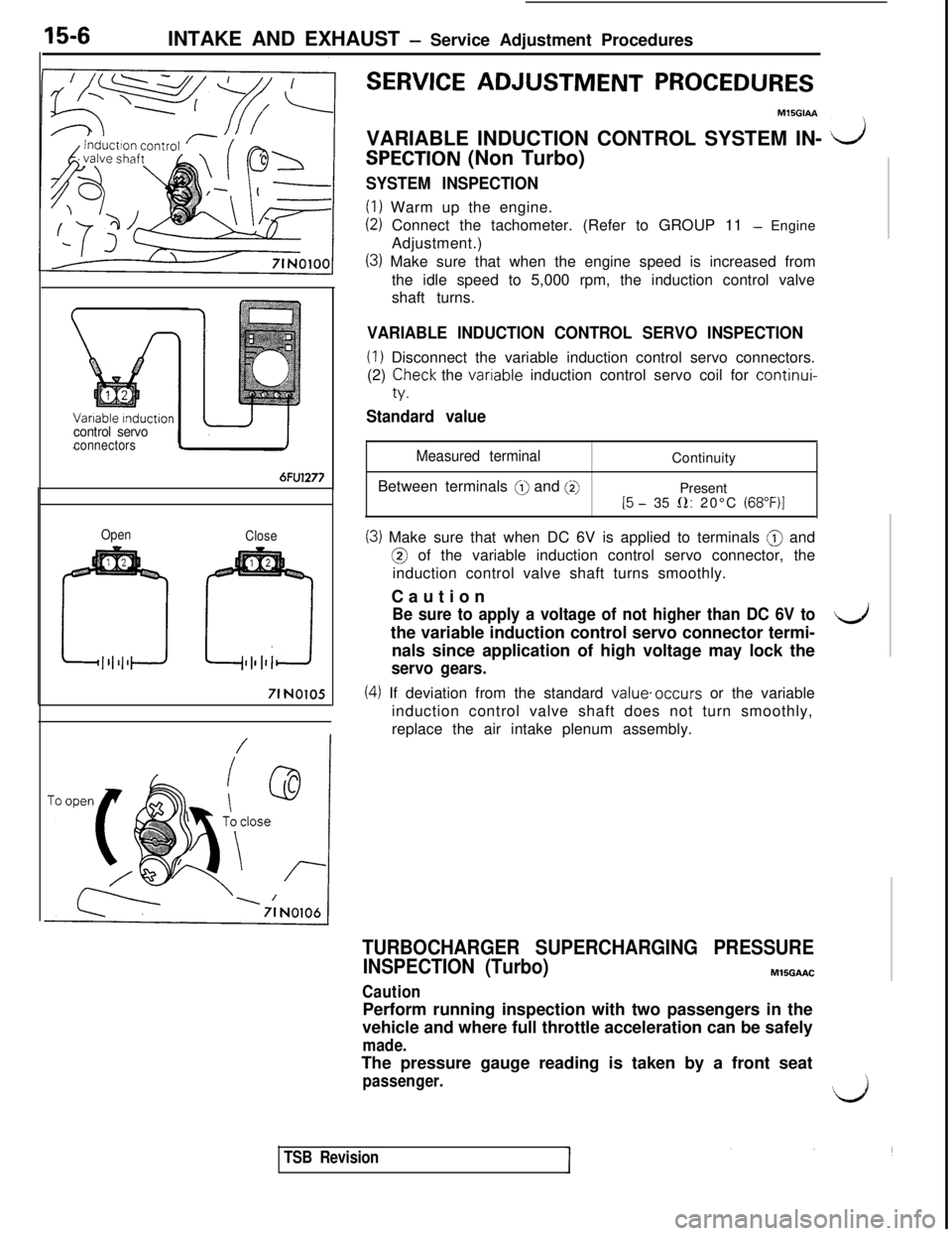
VARIABLE INDUCTION CONTROL SERVO INSPECTION
(1) Disconnect the variable induction control servo connectors.
(2)
Teck the vanable induction control servo coil for continui-
Standard value
Measured terminalBetween terminals
@ and @]Continuity
Present
15 - 35 0: 20°C (68”F)I
(3) Make sure that when DC 6V is applied to terminals @ and@ of the variable induction control servo connector, the
induction control valve shaft turns smoothly.
Caution
Be sure to apply a voltage of not higher than DC 6V tothe variable induction control servo connector termi-4nals since application of high voltage may lock the
servo gears.
(4) If deviation from the standard value.occurs or the variable
induction control valve shaft does not turn smoothly,
replace the air intake plenum assembly.
TURBOCHARGER SUPERCHARGING PRESSURE
INSPECTION (Turbo)MlSGAAC
CautionPerform running inspection with two passengers in the
vehicle and where full throttle acceleration can be safely
made.The pressure gauge reading is taken by a front seat
passenger.‘,k,i
TSB Revision
Page 368 of 1146
a-10CLUTCH - Clutch Control
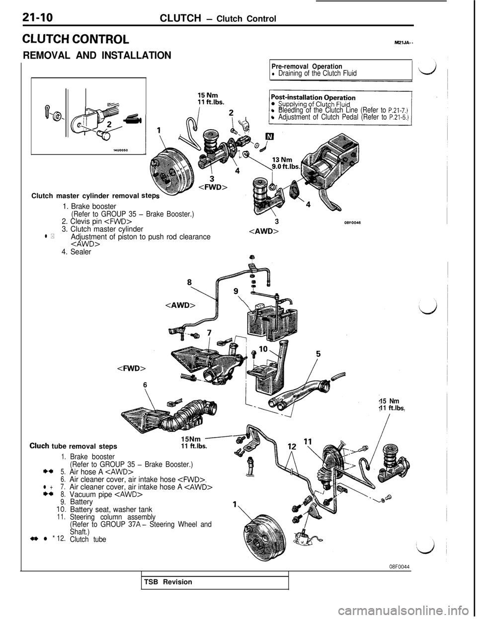
CLUTCH CONTROL
REMOVAL AND INSTALLATIONMZlJA-
-
03% J 2’ti
m
I.“0050I
Pre-removal Operationl Draining of the Clutch Fluid
l Bleeding of the Clutch Line (Refer to P.21-7.)l Adjustment of Clutch Pedal (Refer to P.21-5.)Clutch master cylinder removalstep
1. Brake booster(Refer to GROUP 35 - Brake Booster.)2. Clevis pin
4. Sealer3
9
Cluch tube
1.
**5.
6.
l +7.**8.9.IO.11.
a* l * 12.
removal steps
Brake booster15Nm
-11 ft.lbs.
(Refer to GROUP 35
- Brake Booster.)Air hose A
Battery seat, washer tank
Steering column assembly
(Refer to GROUP 37A- Steering Wheel and
Shaft.)
Clutch tube15 Nm
11
ft.lbs.
08FOO44TSB Revision
Page 586 of 1146
26-10
FRONT AXLE - Hub and KnuckleMB990938-01MB990932-01
/
llR00401 MB991355llL0124
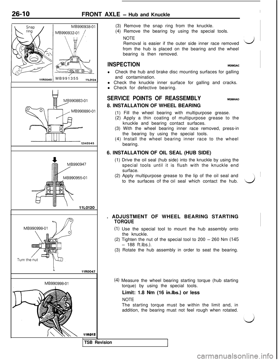
12A0545MB990998-01MB990998-01(3) Remove the snap ring from the knuckle.
(4) Remove the bearing by using the special tools.
NOTERemoval is easier if the outer side inner race removedLJfrom the hub is placed on the bearing and the wheel
bearing is then removed.
INSPECTIONM261GAC
lCheck the hub and brake disc mounting surfaces for galling
and contamination.
l Check the knuckle inner surface for galling and cracks.
l Check for defective bearing.
SERVICE POINTS OF REASSEMBLYMZBIHAO8. INSTALLATION OF WHEEL BEARING
(1) Fill the wheel bearing with multipurpose grease.
(2) Apply a thin coating of multipurpose grease to the
knuckle and bearing contact surfaces.
(3) With the wheel bearing inner race removed, press-in
the bearing by using the special tools.
(4) Install the wheel bearing inner race to the wheel
bearing.
6. INSTALLATION OF OIL SEAL (HUB SIDE)
(1) Drive the oil seal (hub side) into the knuckle by using the
special tools until it is flush with the knuckle end
surface.
(2) Apply multipurpose grease to the lip of the oil seal and
_to the surfaces ot the 011 seal which contact the hub.d. ADJUSTMENT OF WHEEL BEARING STARTING
TORQUE
(I) Use the special tool to mount the hub assembly onto
the knuckle.
(2) Tighten the nut of the special tool to 200
- 260 Nm .(I45
- 188 ft.lbs.).
(3) Rotate the hub assembly in order to seat the bearing.llKO12
TSB Revision
(4) Measure the wheel bearing starting torque (hub starting
torque) by using the special tools.
Limit: 1.8 Nm (16
in.lbs.) or less
NOTEThe starting torque must be within the limit and, in
addition, the bearing must not feel rough when rotated.
Page 599 of 1146
REAR AXLE
llN00261 SERVICE ADJUSTMENT
PRbCEDURES
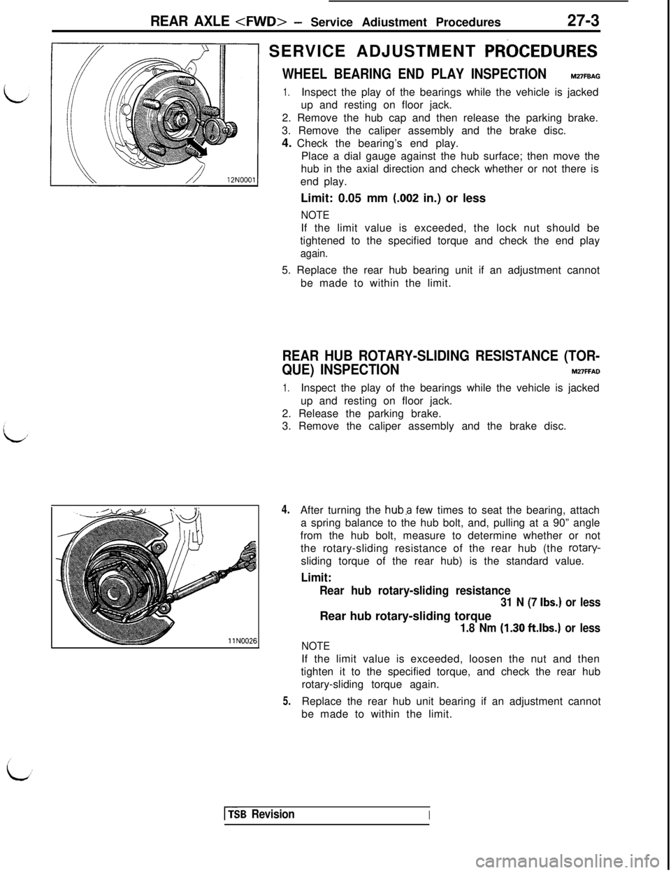
WHEEL BEARING END PLAY INSPECTIONM27FBAG
1.Inspect the play of the bearings while the vehicle is jacked
up and resting on floor jack.
2. Remove the hub cap and then release the parking brake.
3. Remove the caliper assembly and the brake disc.
4. Check the bearing’s end play.
Place a dial gauge against the hub surface; then move the
hub in the axial direction and check whether or not there is
end play.
Limit: 0.05 mm
(.002 in.) or less
NOTEIf the limit value is exceeded, the lock nut should be
tightened to the specified torque and check the end play
again.5. Replace the rear hub bearing unit if an adjustment cannot
be made to within the limit.
REAR HUB ROTARY-SLIDING RESISTANCE (TOR-
QUE) INSPECTION
M27FFAD
1.Inspect the play of the bearings while the vehicle is jacked
up and resting on floor jack.
2. Release the parking brake.
3. Remove the caliper assembly and the brake disc.
4.
5.After turning the
huba few times to seat the bearing, attach
a spring balance to the hub bolt, and, pulling at a 90” angle
from the hub bolt, measure to determine whether or not
the rotary-sliding resistance of the rear hub (the rotary-
sliding torque of the rear hub) is the standard value.
Limit:
Rear hub rotary-sliding resistance
31 N (7 Ibs.) or lessRear hub rotary-sliding torque
1.8 Nm (1.30 ft.lbs.) or less
NOTEIf the limit value is exceeded, loosen the nut and then
tighten it to the specified torque, and check the rear hub
rotary-sliding torque again.
Replace the rear hub unit bearing if an adjustment cannot
be made to within the limit.
[fsB RevisionI
Page 631 of 1146
REAR AXLE
MB990802-01
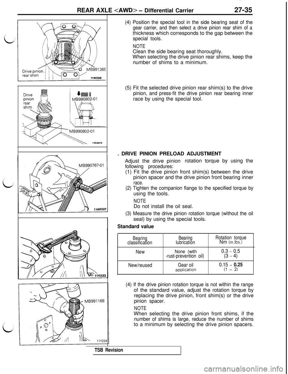
(4) Position the special tool in the side bearing seat of the
gear carrier, and then select a drive pinion rear shim of athickness which corresponds to the gap between the
special tools.
NOTEClean the side bearing seat thoroughly.
When selecting the drive pinion rear shims, keep the
number of shims to a minimum.
(5) Fit the selected drive pinion rear shim(s) to the drive
pinion, and press-fit the drive pinion rear bearing innerrace by using the special tool.
. DRIVE PINION PRELOAD ADJUSTMENT
Adjust the drive pinionrotation torque by using the
following procedures:(1) Fit the drive pinion front shim(s) between the drive
pinion spacer and the drive pinion front bearing inner
race.
(2) Tighten the companion flange to the specified torque byusing the tools.
NOTEDo not install the oil seal.
(3) Measure the drive pinion rotation torque (without the oilseal) by using the special tools.
Standard value
Bearingclassification
New
New/reusedBearing
lubrication
None (with-rust-prevention oil)
Gear oil
amlication
Rotation torqueNm (in.lbs.)
0.3 - 0.5
(3
- 4)
0.15 - 0.25
(I - 2)
(4) If the drive pinion rotation torque is not within the rangeof the standard value, adjust the rotation torque by
replacing the drive pinion, front shim(s) or the drive
pinion spacer.
NOTEWhen selecting the drive pinion front shims, if the
number of shims is large, reduce the number of shimsto a minimum by selecting the drive pinion spacers.
TSB Revision
Page 692 of 1146
34-6REAR SUSPENSION
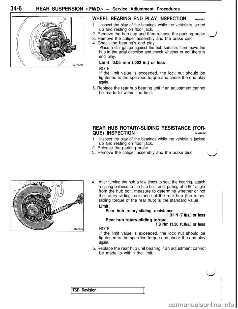
WHEEL BEARING END PLAY INSPECTIONM34FBAG
1.Inspect the play of the bearings while the vehicle is jackedup and resting on floor jack.
2. Remove the hub cap and then release the parking brake.
s&i3. Remove the caliper assembly and the brake disc.
4. Check the bearing’s end play.
Place a dial gauge against the hub surface; then move the
hub in the axial direction and check whether or not there is
end play.Limit: 0.05 mm
(.002 in.) or less
NOTEIf the limit value is exceeded, the lock nut should be
tightened to the specified torque and check the end play
again.5. Replace the rear hub bearing unit if an adjustment cannot
be made to within the limit.
REAR HUB ROTARY-SLIDING RESISTANCE (TOR-
QUE) INSPECTION
M34FCAC
1.Inspect the play of the bearings while the vehicle is jackedup and resting on floor jack.
2. Release the parking brake.
3. Remove the caliper assembly and the brake disc.
..J
4.After turning the hub a few times to seat the bearing, attach
a spring balance to the hub bolt, and, pulling at a 90” anglefrom the hub bolt, measure to determine whether or not
the rotary-sliding resistance of the rear hub (the
rotary-sliding torque of the rear hub) is the standard value.
Limit:
Rear hub rotary-sliding resistance
31 N (7 Ibs.) or lessRear hub rotary-sliding torque
1.8 Nm (1.30 ftlbs.) or less
NOTEIf the limit value is exceeded, the lock nut should be
tightened to the specified torque and check the end play
again.5. Replace the rear hub unit bearing if an adjustment cannot
be made to within the limit.
TSB Revision
Page 889 of 1146
BODY - Service Adjustment Procedures
42-17
I18FOO33
Front floor pan+ Drain plug
lFlFOO91
18FOO9132. If out of specifications, adjust as described below.@ Remove the door trim. (Refer to
P.42-41.)@ Loosen the screw attaching the inside handle and slide
the inside handle back and forth to adjust the inside
handle play.
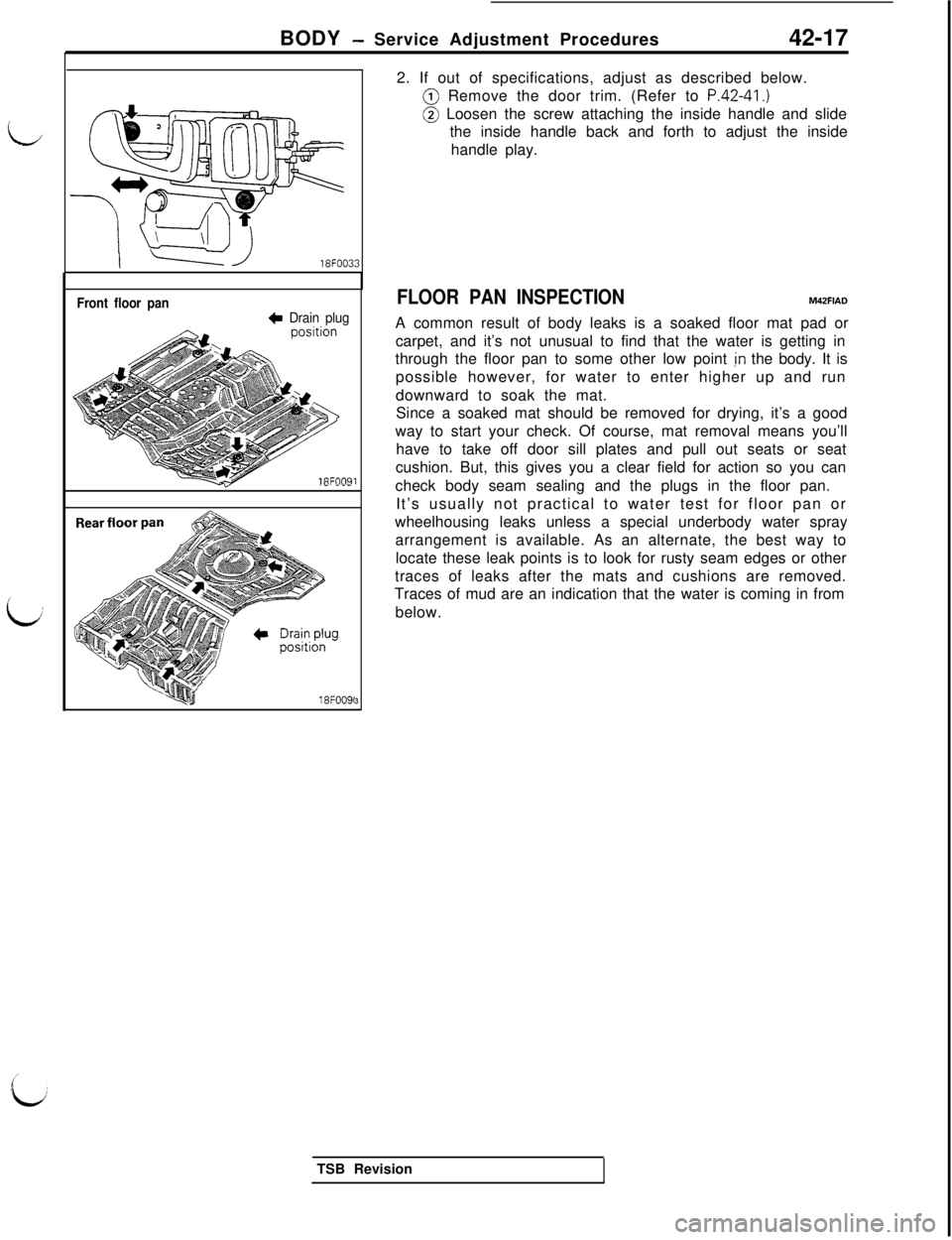
FLOOR PAN INSPECTIONM42FIADA common result of body leaks is a soaked floor mat pad or
carpet, and it’s not unusual to find that the water is getting in
through the floor pan to some other low point
jn the body. It is
possible however, for water to enter higher up and run
downward to soak the mat.
Since a soaked mat should be removed for drying, it’s a good
way to start your check. Of course, mat removal means you’ll
have to take off door sill plates and pull out seats or seat
cushion. But, this gives you a clear field for action so you can
check body seam sealing and the plugs in the floor pan.
It’s usually not practical to water test for floor pan or
wheelhousing leaks unless a special underbody water spray
arrangement is available. As an alternate, the best way to
locate these leak points is to look for rusty seam edges or other
traces of leaks after the mats and cushions are removed.
Traces of mud are an indication that the water is coming in from
below.
TSB Revision