sensor MITSUBISHI 3000GT 1992 2.G Workshop Manual
[x] Cancel search | Manufacturer: MITSUBISHI, Model Year: 1992, Model line: 3000GT, Model: MITSUBISHI 3000GT 1992 2.GPages: 738, PDF Size: 35.06 MB
Page 480 of 738
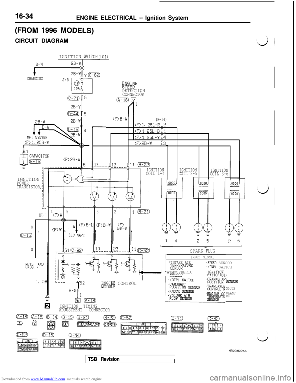
Downloaded from www.Manualslib.com manuals search engine 16-34ENGINE ELECTRICAL - Ignition System
(FROM 1996 MODELS)CIRCUIT DIAGRAM
IGNITION SWITCH(IG1)
B-W
iCHARGINGJ/B
Eiwi"
/DETECTION
(c-73)“5CONNECTOR
2B-Y
(D-44)“5
2B-W-I
2B-W
MFILS - --
(F>B-W(B-14)
(F)l. 25L-R,,2
(F)1.25L-B;,l
(F>1.25L-Yj,4
(F>2B-W ),3-
.
13,<2------ ---__,,11 (8-22),\,\IGNITIONCOIL l-4IGNITION
COIL 2-5IGNITIONCOIL 3-6-4III(r
,cl
(F>2B-W
IGNITION /POWER
TRANSISTOR;
I
(F)'
\I\/,I--------------
-----
-----
I5(F)W321m
BR-RW
(D-15)2
W
METE1GAUGI*AND)3 6
\-I
G9SPARK PLU4
9 41INPUT SIGNAL
*INTAKE AIRg;#j#ATURE
"-b- bkl *ATMOSPHERIC9FLTcno
-SPEED SENSOR.(PNP) SWITCH.-.-..
, 4””
---- 521ENG:h!E CONTROLMODI
TENSOR
ODULE
OLANT
RE
IGNITION TIMING
ADJUSTMENT CONNECTOR
1. 25
HR03M02AA
TSB Revision1
Page 481 of 738

Downloaded from www.Manualslib.com manuals search engine i;ENGINE ELECTRICAL
- Ignition System16-35
OPERATIONl
Turn ignition switch to .“ON”position, and batteryvoltage will be applied to primary winding of
ignition coil.l
When crankshaft position sensor and camshaft
position sensor signal is input to engine control
module, engine control module makes ON-OFF
control of power transistors one by one.l When power transistor is turned on, current
flows from ignition coil (primary winding) to
ground through power transistor.l When power transistor A is turned from ON
to OFF, the spark plugs of No. 1 and No. 4
cylinders spark. Turning of power transistor B
from ON to OFF will produce sparking in spark
plugs of No. 2 and No. 5 cylinders. Furthermore,
when power transistor C is turned from ON toOFF, sparking is produced in spark plugs of
No. 3 and No. 6 cylinders.
TROUBLESHOOTING HINTS1. Engine cranks, but does not start.
(1) Spark is insufficient or does not occur at
all (on spark plug).l Check ignition coil.
l Check camshaft position sensor and
crankshaft position sensorl Check power transistor.
l Check spark plugs.
l Check spark plug cable.
(2) Spark is good.
l Check ignition timing.
2. Engine idles roughly or stalls.
l Check spark plugs.
l Check ignition timing.
l Check ignition coil.
l Check spark plug cable.
3. Poor acceleration
l Check ignition timing.
l Check spark plug cable.
l Check ignition coil.
TSB Revision
Page 491 of 738
Downloaded from www.Manualslib.com manuals search engine ENGINE ELECTRICAL - Ignition System16-45 l
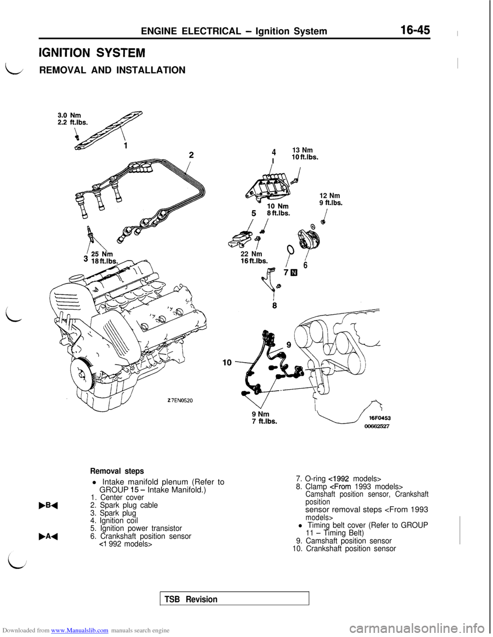
IGNITION SYSTEM
LREMOVAL AND INSTALLATIONI
i
27EN0520
413 NmIlOft.lbs.
d
12 Nm
9 ft.lbs.
22 Nm16ftAbs.B678
W1
,A4
Removal stepsl Intake manifold plenum (Refer to
GROUP
1.5 - Intake Manifold.)1. Center cover
2. Spark plug cable
3. Spark plug
4. Ignition coil
5. Ignition power transistor
6. Crankshaft position sensor
cl 992 models>9 Nm
7
ft.lbs.u 16FO453
00662527
7. O-ring cl992 models>
8. Clamp
positionsensor removal steps
11 - Timing Belt)
9. Camshaft position sensor
10. Crankshaft position sensor
TSB Revision
Page 492 of 738
Downloaded from www.Manualslib.com manuals search engine 16-46ENGINE ELECTRICAL - Ignition Svstem
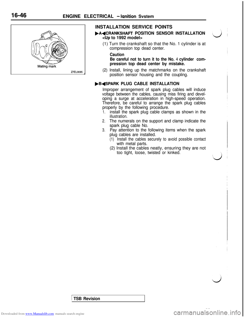
27ELOO95JINSTALLATION SERVICE POINTS.A+CRANKSHAFT
POSITION SENSOR INSTALLATION
(1) Turn the crankshaft so that the No. 1 cylinder is at
compression top dead center.
Caution
Be careful not to turn it to the No.
4 cylinder com-
pression top dead center by mistake.
(2) Install, lining up the matchmarks on the crankshaft
position sensor housing and the coupling.
,B+SPARK PLUG CABLE INSTALLATION
Improper arrangement of spark plug cables will induce
voltage between the cables, causing miss firing and devel-
oping a surge at acceleration in high-speed operation.
Therefore, be careful to arrange the spark plug cables
properly by the following procedure.
1.install the spark plug cable clamps as shown in the
illustration.
2.The numerals on the support and clamp indicate the
spark plug cable No.
3.Pay attention to the following items when the spark
plug cables are installed.
(1)Install the cables securely to avoid possible contact
with metal parts.(2) Install the cables neatly, ensuring they are not
too tight, loose, twisted or kinked.
/ TSB Revision
Page 497 of 738
Downloaded from www.Manualslib.com manuals search engine 54-1
CHASSIS
ELECTRICAL
CONTENTS
AERO PARTS (ACTIVE AERO).....Refer to GROUP 51
ANTI-LOCK BRAKING SYSTEM....
Refer to GROUP 35
BATTERY...........................................-3
ON-VEHICLE SERVICE............................3
Battery Charging.................................4Battery Inspection................................3Battery Testing Procedure........................5
SPECIFICATIONS................................-3
General Specifications............................3
CIGARETTE LIGHTER.............................119
CIGARETTE LIGHTER..........................123
SPECIFICATIONS..............................
119
General Specifications............I...........119
TROUBLESHOOTING............................120
COLUMN SWITCH.................................
.lll
COLUMN SWITCH*............................112
SPECIAL TOOL.................................111
SPECIFICATIONS...............................111
General Specifications..........................111
CRUISE CONTROL SYSTEM . . . . . . . Refer to GROUP 17
DOOR GLASS AND REGULATOR
(POWER WINDOWS) . . . . . . . . . . . . . .Refer to GROUP 42
DOOR HANDLE AND LATCH
(CENTRAL DOOR LOCKING) . . . . . . Refer to GROUP 42
DOOR MIRROR (ELECTRONIC
CONTROLLED MIRROR). . . . . . . . . . .Refer to GROUP 51
ELECTRONIC CONTROL
SUSPENSION . . . . . . . . . . . . . . . . . . . . Refer to GROUP
338
FRONT SEAT (POWER SEAT) . . . . Refer to GROUP 52A
HEATER AND AIR CONDITIONING . Refer to GROUP 55
HORN. . . . . . . . . . . . . . . . . . . . . . . . . . . . . . . . . . . . . . . . . . . .
115
HORN SWITCH* . . . . . . . . . . . . . . . . . . . . . . . . . . . . . . .118
RELAY. . . . . . . . . . . . . . . . . . . . . . . . . . . . . . . . . . . . . . . .
118
SPECIFICATIONS. . . . . . . . . . . . . . . . . . . . . . . . . . . . . .
115
General Specifications . . . . . . . . . . . . . . . . . . . . . . . .115
TROUBLESHOOTING . . . . . . . . . . . . . . . . . . . . . . . . . . .115
KEYLESS ENTRY SYSTEM
(CENTRAL DOOR LOCKING) . . . . . . Refer to GROUP 42
CONTINUED ON NEXT PAGE
WARNINGS REGARDING SERVICING OF SUPPLEMENTAL RESTRAINT SYSTEM (SRS) EQUIPPED VEHICLES
WARNING!
(1) Improper service or maintenance of any component of the
SRS, or any SRS-related component, can lead to personal
injury or death to service personnel (from inadvertent firing of the air bag) or to the driver and passenger (from render-
ing the SRS inoperative).
(2) Service or maintenance of any SRS component or
SRS-related component must be performed only at an authorized
MITSUBISHI dealer.
(3)MITSUBISHI dealer personnel must thoroughly review this manual, and especially its GROUP 52B
TSupplemental Re-
straint System (SRS) and GROUP 00 -Maintenance Service before beginning any service or maintenance of any com-
ponent of the SRS or any
SRS-related component.
NOTE
The SRS includes the following components: impact sensors, SRS diagnosis unit, SRS warning light, air bag module, clock spring
and interconnecting wiring. Other SRS-related components (that may
h,a”” to be removed/installed in connection with SRS serviceor maintenance) are indicated in the table of contents by an asterisk ( ).
Page 514 of 738
Downloaded from www.Manualslib.com manuals search engine 54-18CHASSIS ELECTRICAL - Meters and Gauges
OPERATION
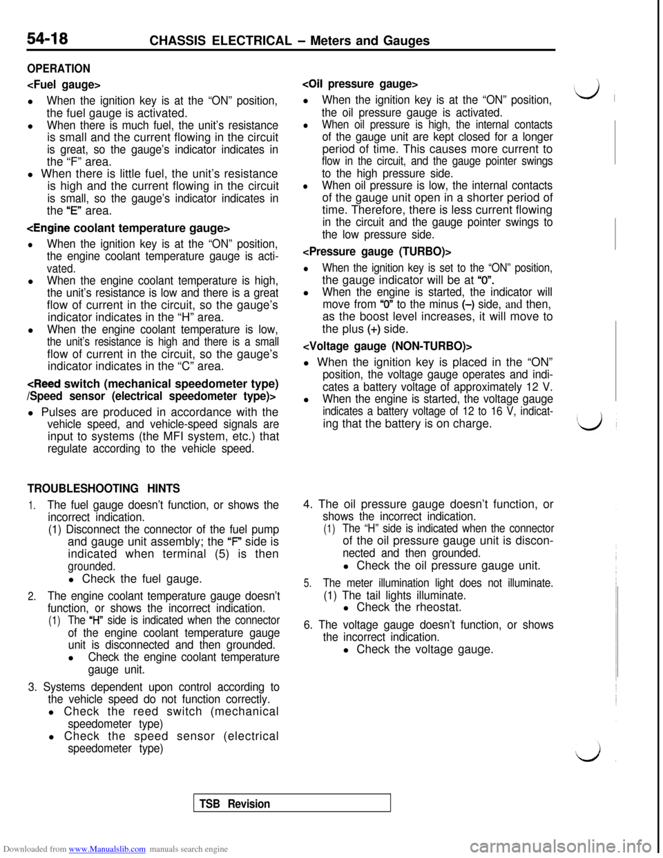
When the ignition key is at the “ON” position,the fuel gauge is activated.
l
When there is much fuel, the unit’s resistanceis small and the current flowing in the circuit
is great, so the gauge’s indicator indicates inthe “F” area.
l When there is little fuel, the unit’s resistance
is high and the current flowing in the circuit
is small, so the gauge’s indicator indicates inthe
“E” area.
lWhen the ignition key is at the “ON” position,
the engine coolant temperature gauge is acti-
vated.l
When the engine coolant temperature is high,
the unit’s resistance is low and there is a greatflow of current in the circuit, so the gauge’s
indicator indicates in the “H” area.
l
When the engine coolant temperature is low,
the unit’s resistance is high and there is a smallflow of current in the circuit, so the gauge’s
indicator indicates in the “C” area.
vehicle speed, and vehicle-speed signals areinput to systems (the MFI system, etc.) that
regulate according to the vehicle speed.
TROUBLESHOOTING HINTS
1.The fuel gauge doesn’t function, or shows the
incorrect indication.
(1) Disconnect the connector of the fuel pumpand gauge unit assembly; the ‘F” side is
indicated when terminal (5) is then
grounded.l Check the fuel gauge.
2.The engine coolant temperature gauge doesn’t
function, or shows the incorrect indication.
(1)The “l-l” side is indicated when the connector
of the engine coolant temperature gauge
unit is disconnected and then grounded.l
Check the engine coolant temperature
gauge unit.
3. Systems dependent upon control according to
the vehicle speed do not function correctly.l Check the reed switch (mechanical
speedometer type)l Check the speed sensor (electrical
speedometer type)
coil pressure gauge>l
When the ignition key is at the “ON” position,
the oil pressure gauge is activated.
lWhen oil pressure is high, the internal contacts
of the gauge unit are kept closed for a longerperiod of time. This causes more current to
flow in the circuit, and the gauge pointer swings
to the high pressure side.
lWhen oil pressure is low, the internal contactsof the gauge unit open in a shorter period of
time. Therefore, there is less current flowing
in the circuit and the gauge pointer swings to
the low pressure side.
lWhen the ignition key is set to the “ON” position,the gauge indicator will be at
“0”.l
When the engine is started, the indicator will
move from
“0” to the minus (-) side, and then,as the boost level increases, it will move to
the plus
(+) side.
position, the voltage gauge operates and indi-
cates a battery voltage of approximately 12 V.l
When the engine is started, the voltage gauge
indicates a battery voltage of 12 to 16 V, indicat-ing that the battery is on charge.
4. The oil pressure gauge doesn’t function, or
shows the incorrect indication.
(1)The “H” side is indicated when the connectorof the oil pressure gauge unit is discon-
nected and then grounded.l Check the oil pressure gauge unit.
5.The meter illumination light does not illuminate.
(1) The tail lights illuminate.l Check the rheostat.
6. The voltage gauge doesn’t function, or shows
the incorrect indication.l Check the voltage gauge.
TSB Revision
Page 517 of 738
Downloaded from www.Manualslib.com manuals search engine CHASSIS ELECTRICAL - Meters and Gauges54-21
L
IGN:IONsw1:-I (ST)IGNISWIT
2B-'
2B-IB-‘
z(c-31)
B-‘
1
_--11 1
J/B
r
G
151
2B-I
i
2B-I
(A-67)
2B-1
1.25B-\
1.25B-\11
/
1
kTARTERIRELAY.'OFFINim
3
G-E3 /
(c-02)3 i.--J
3G-E
EK”&#ON
l(D-15)
DIODE
E0.85B-'w
E0.85B-'
B-1r----
Ic
1 B-1IIIE
II4wsIIEW1OFF '*ON SENSORII
j Y-G
*q (A-30)
9L----~\
IN(IGl)
'(c-82)
1
i(c-71)
i(D-44)
I(D-45)
L
u(Y-G)0
D-10Y-G
66
COMBINATION
METER
(D-04)
64B
2B
1p(D-41)
28
(A-09X) (A-30)@%?')(c-02)(c-31)(c-71)(C-82)0
/
HRlOM03AB
TSB Revision
Page 520 of 738
Downloaded from www.Manualslib.com manuals search engine 54-24CHASSIS ELECTRICAL - Meters -and Gauges
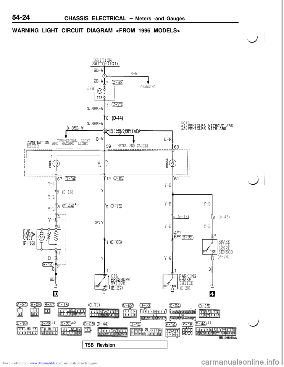
WARNING LIGHT CIRCUIT DIAGRAM
IGNSWI'28-ITICTCH
2B-
J/B
0.85B-
0.858,0.85B-W
TURN-SIGNAL LIGHTCOMBINATION AND HAZARD LIGHTMETER
AL
'6.W
“6
-W
13
-W
cc7T,
I y, ,
‘8"11
;;i;EW;EElg jV;V;O&ABS
:B:CONVERTIBLE
j9METER ANDGAUGES~r-----------r -------- -- _______
IIIiizzIcI
L--------‘:67 o
Y-L
"9 (D-16)
Y-L
y-L‘18 (F-44)%3‘y-1
Y-L
I(F)
t1
;B-R
I
IN(IGl)
B-W
G----l
1
CHARGING
(c-71)
(D-44)NOTE
II
.2 (D-03)-----J61
LL
'3
Y
(c
,Y
Y-B
0
Y-BY-B
“5 (c-15)“2 (D-45)
Y-BY-B
4:1
;>6:*=s,2
BRAKE
FLUID
LEVEL
OFF '*ONSENSOR
*(I (A-24)
1
1
OIL;@SRE
((B-37)
/
131
;~M&NG
SWITCH
(D-28)a
TSB Revision
Page 524 of 738
Downloaded from www.Manualslib.com manuals search engine 54-28CHASSIS ELECTRICAL - Meters and Gauges
16FO11500002300
16Fo255 00002383
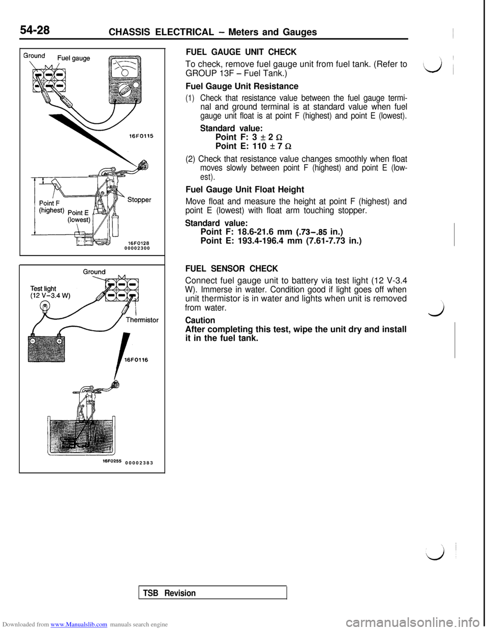
FUEL GAUGE UNIT CHECKTo check, remove fuel gauge unit from fuel tank. (Refer to
GROUP 13F
- Fuel Tank.)
Fuel Gauge Unit Resistance
(1)Check that resistance value between the fuel gauge termi-
nal and ground terminal is at standard value when fuel
gauge unit float is at point F (highest) and point E (lowest).
Standard value:Point F: 3
If: 2 GPoint E: 110
It 7 Q
(2) Check that resistance value changes smoothly when float
moves slowly between point F (highest) and point E (low-
est).Fuel Gauge Unit Float Height
Move float and measure the height at point F (highest) and
point E (lowest) with float arm touching stopper.
Standard value:Point F: 18.6-21.6 mm (.73-.85 in.)
Point E: 193.4-196.4 mm (7.61-7.73 in.)
FUEL SENSOR CHECKConnect fuel gauge unit to battery via test light (12 V-3.4
W). Immerse in water. Condition good if light goes off whenunit thermistor is in water and lights when unit is removed
from water.
CautionwAfter completing this test, wipe the unit dry and install
it in the fuel tank.
TSB Revision
Page 527 of 738
Downloaded from www.Manualslib.com manuals search engine CHASSIS ELECTRICAL - Meters and Gauges54-31
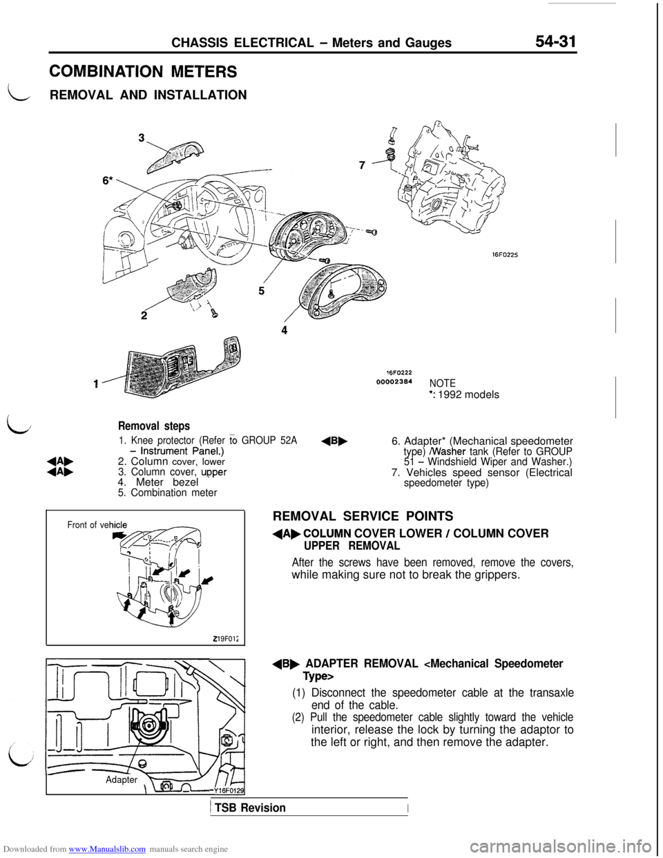
COMBINATION METERS
LREMOVAL AND INSTALLATION
76FO22200002364
NOTE
*: 1992 models
L/
:i:
- lnstiument PineI.)
2. Column cover, lower
3. Column cover, upper 1. Knee protector (Refer
G GROUP 52A4. Meter bezel
* ’5. Combination meter
Removal steps6. Adapter* (Mechanical speedometer
type) /Washer tank (Refer to GROUP
51 - Windshield Wiper and Washer.)7. Vehicles speed sensor (Electrical
Front of ve
219FOl;
speedometer type)REMOVAL SERVICE POINTS
dAbCOLUMN COVER LOWER / COLUMN COVER
UPPER REMOVAL
After the screws have been removed, remove the covers,while making sure not to break the grippers.
dB, ADAPTER REMOVAL
(1) Disconnect the speedometer cable at the transaxle
end of the cable.
(2) Pull the speedometer cable slightly toward the vehicleinterior, release the lock by turning the adaptor to
the left or right, and then remove the adapter.
Adapter-Y16FO129],
) TSB RevisionI