light MITSUBISHI 3000GT 1992 2.G Workshop Manual
[x] Cancel search | Manufacturer: MITSUBISHI, Model Year: 1992, Model line: 3000GT, Model: MITSUBISHI 3000GT 1992 2.GPages: 738, PDF Size: 35.06 MB
Page 516 of 738
Downloaded from www.Manualslib.com manuals search engine 54-20CHASSIS ELECTRICAL - Meters and Gauges
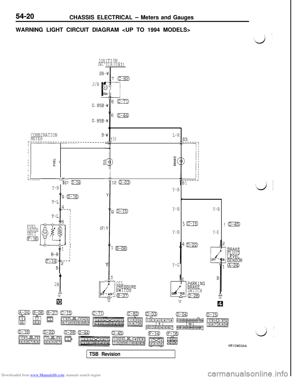
WARNING LIGHT CIRCUIT DIAGRAM
IGNSWI'IT1TCHON(IGl)
J/B
r
G
15
0.85B-
0.858.
COMBINATIONMETERB-
r------------------------------.I
I
III
I
IId <21I0III
L--- ----- -G6? ~
Y-B
GiD-15)Y-B
FUEL
GAUGE
UNIT
m
(F:J
II
2B
1
Y
r
)Y
1
Y
3
I
OIL$$#RE
Lm
L-R59
12 (D-03)
Y-B
c
I
Y-B
Y-G
/\@F&NG
OFF -SWITCHONkm
Y-B
Y-E
HRlOM03AA
TSB Revision
Page 518 of 738
Downloaded from www.Manualslib.com manuals search engine CHASSIS ELECTRICAL - Meters and Gauges
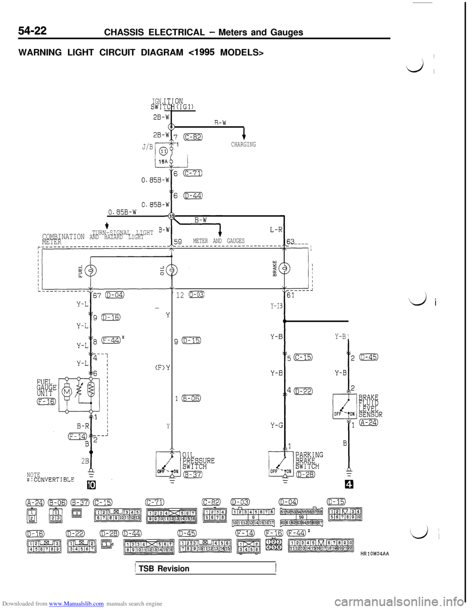
WARNING LIGHT CIRCUIT DIAGRAM
cl995 MODELS>I
dl
IGN.SWI:IN(IGl)
2B-
2B-
R-W
‘(c-82)1CHARGINGJ/B
I-15
0.858-AEW
E
,W
I
13
,W
5;(D-44)
0.858-0.85B-W
L-T
39METER AND GAUGES_______--_----------------
+TURN-SIGNAL LIGHT B-COMBINATION AND HAZARD LIGHTMETER$3-----
-.
1
--i
) ;
.-----l31
LL,
Y
‘Y
Y
,\1T-
2B
dNOTEFLOFF -0
::CONVERTIBLE=
‘d i
12 (D-03)
Y-I
Y-BIJ(D-15)Y-i
Y-i
l(B-06)
Y-C
-iniTr--
HRlOM04AA
1 TSB Revision
Page 520 of 738
Downloaded from www.Manualslib.com manuals search engine 54-24CHASSIS ELECTRICAL - Meters -and Gauges
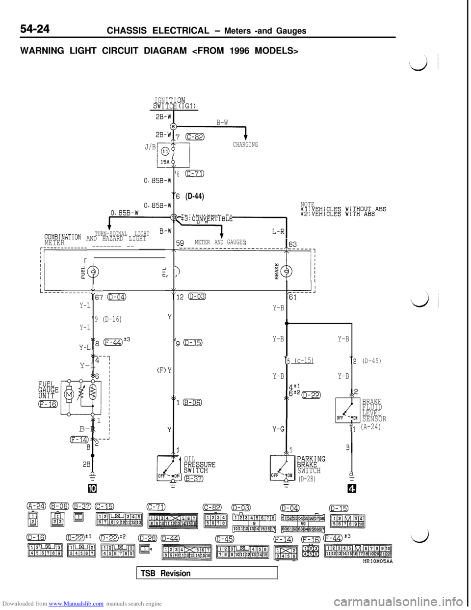
WARNING LIGHT CIRCUIT DIAGRAM
IGNSWI'28-ITICTCH
2B-
J/B
0.85B-
0.858,0.85B-W
TURN-SIGNAL LIGHTCOMBINATION AND HAZARD LIGHTMETER
AL
'6.W
“6
-W
13
-W
cc7T,
I y, ,
‘8"11
;;i;EW;EElg jV;V;O&ABS
:B:CONVERTIBLE
j9METER ANDGAUGES~r-----------r -------- -- _______
IIIiizzIcI
L--------‘:67 o
Y-L
"9 (D-16)
Y-L
y-L‘18 (F-44)%3‘y-1
Y-L
I(F)
t1
;B-R
I
IN(IGl)
B-W
G----l
1
CHARGING
(c-71)
(D-44)NOTE
II
.2 (D-03)-----J61
LL
'3
Y
(c
,Y
Y-B
0
Y-BY-B
“5 (c-15)“2 (D-45)
Y-BY-B
4:1
;>6:*=s,2
BRAKE
FLUID
LEVEL
OFF '*ONSENSOR
*(I (A-24)
1
1
OIL;@SRE
((B-37)
/
131
;~M&NG
SWITCH
(D-28)a
TSB Revision
Page 521 of 738
Downloaded from www.Manualslib.com manuals search engine CHASSIS ELECTRICAL - Meters and Gauaes
i
L/
IGNISW17
2B-\1
28-l
2B-\I
2B-‘1
(A-67)
2B-Y
STARTING
SUPPLEMENTAL
~E~&~J$NT
----------.+OFFIN
13
i
G-B
3(c-02) 3--
G-B
1.25B-Y
+MFI SYSTEM
'(D-15)DIODE
1.25B-Yu
I
IGNITIONSWITCH(IG1)
J/B
ml
0
15A“6
(D-44)
0.85B-W
B-W(130.85B-W
METER AND
GAUGESB-WTURN-SIGNAL LIGHT
r----+$30AND HAZARD LIGHT
i B-W
9
i;yEKNATION
(D-04)
HRlOM05AB
TSB Revision
Page 523 of 738
Downloaded from www.Manualslib.com manuals search engine I,;CHASSIS ELECTRICAL
- Meters and Gauges54-27
c I\\ zl6F024;
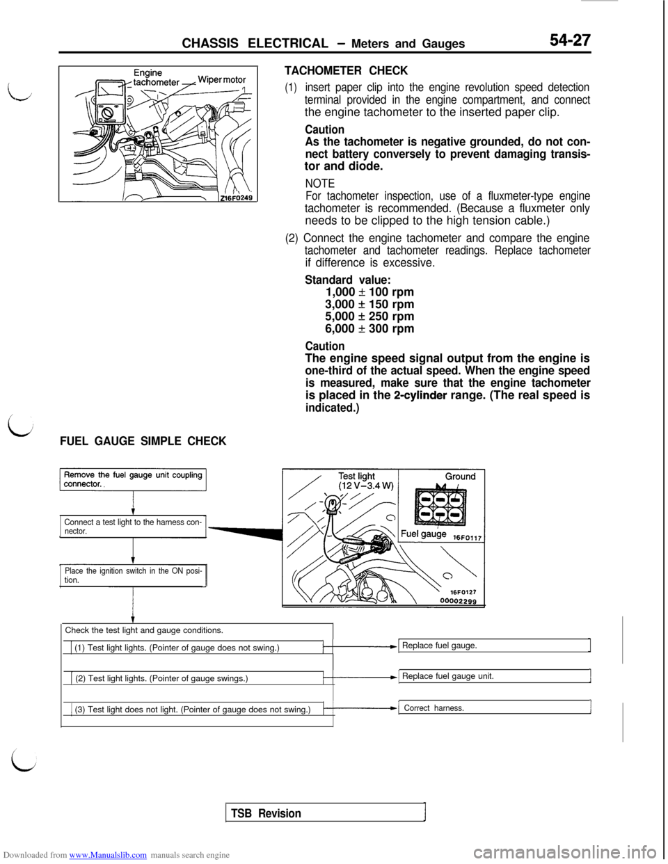
L:FUEL GAUGE SIMPLE CHECKTACHOMETER CHECK
(1)insert paper clip into the engine revolution speed detection
terminal provided in the engine compartment, and connectthe engine tachometer to the inserted paper clip.
Caution
As the tachometer is negative grounded, do not con-
nect battery conversely to prevent damaging transis-tor and diode.
NOTE
For tachometer inspection, use of a fluxmeter-type engine
tachometer is recommended. (Because a fluxmeter onlyneeds to be clipped to the high tension cable.)
(2) Connect the engine tachometer and compare the engine
tachometer and tachometer readings. Replace tachometer
if difference is excessive.
Standard value:1,000
f 100 rpm
3,000
+ 150 rpm
5,000
f 250 rpm
6,000
f 300 rpm
CautionThe engine speed signal output from the engine is
one-third of the actual speed. When the engine speed
is measured, make sure that the engine tachometeris placed in the
2-cylinder range. (The real speed is
indicated.)
Connect a test light to the harness con-nector.
Place the ignition switch in the ON posi-
tion.Check the test light and gauge conditions.
1 (1) Test light lights. (Pointer of gauge does not swing.)/-.-I Replace fuel gauge.
[ (2) Test light lights. (Pointer of gauge swings.)/-.--I Replace fuel gauge unit.1
1 (3) Test light does not light. (Pointer of gauge does not swing.)k-1 Correct harness.I
TSB Revision
Page 524 of 738
Downloaded from www.Manualslib.com manuals search engine 54-28CHASSIS ELECTRICAL - Meters and Gauges
16FO11500002300
16Fo255 00002383
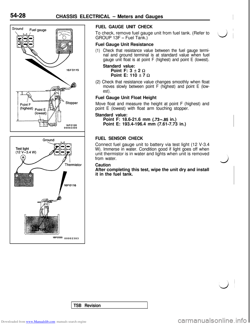
FUEL GAUGE UNIT CHECKTo check, remove fuel gauge unit from fuel tank. (Refer to
GROUP 13F
- Fuel Tank.)
Fuel Gauge Unit Resistance
(1)Check that resistance value between the fuel gauge termi-
nal and ground terminal is at standard value when fuel
gauge unit float is at point F (highest) and point E (lowest).
Standard value:Point F: 3
If: 2 GPoint E: 110
It 7 Q
(2) Check that resistance value changes smoothly when float
moves slowly between point F (highest) and point E (low-
est).Fuel Gauge Unit Float Height
Move float and measure the height at point F (highest) and
point E (lowest) with float arm touching stopper.
Standard value:Point F: 18.6-21.6 mm (.73-.85 in.)
Point E: 193.4-196.4 mm (7.61-7.73 in.)
FUEL SENSOR CHECKConnect fuel gauge unit to battery via test light (12 V-3.4
W). Immerse in water. Condition good if light goes off whenunit thermistor is in water and lights when unit is removed
from water.
CautionwAfter completing this test, wipe the unit dry and install
it in the fuel tank.
TSB Revision
Page 525 of 738
Downloaded from www.Manualslib.com manuals search engine CHASSIS ELECTRICAL - Meters and Gauaes
i
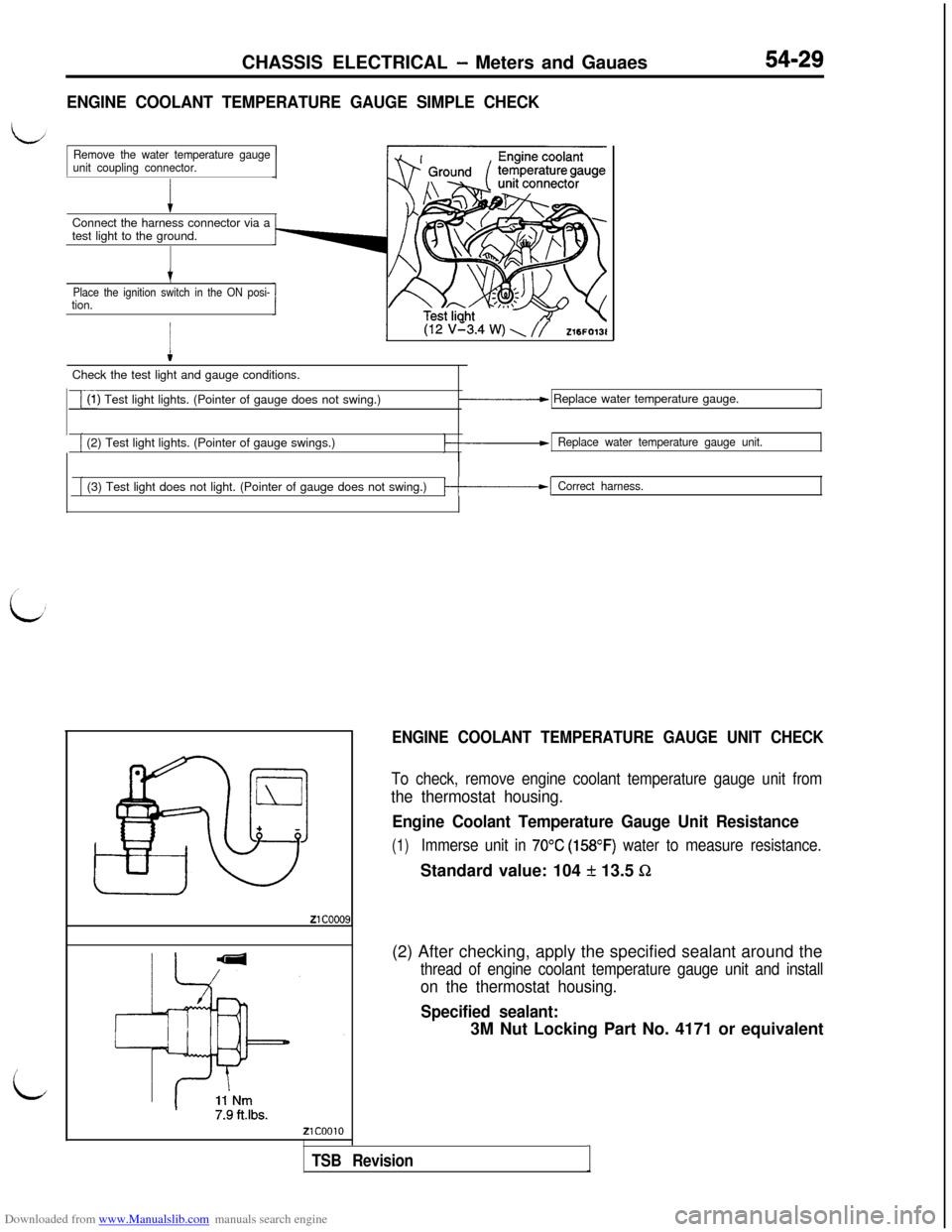
ENGINE COOLANT TEMPERATURE GAUGE SIMPLE CHECKConnect the harness connector via a
test light to the ground.
Remove the water temperature gauge
unit coupling connector.
t
Place the ignition switch in the ON posi-tion.
I
(12 v’3.4 w) \ //Z16FO13lCheck the test light and gauge conditions.
i(1) Test light lights. (Pointer of gauge does not swing.)_____c Replace water temperature gauge.
[ (2) Test light lights. (Pointer of gauge swings.)Replace water temperature gauge unit.
[ (3) Test light does not light. (Pointer of gauge does not swing.)/-------I Correct harness.
ENGINE COOLANT TEMPERATURE GAUGE UNIT CHECK
To check, remove engine coolant temperature gauge unit from
the thermostat housing.
Engine Coolant Temperature Gauge Unit Resistance
(1)Immerse unit in 70°C (158OF) water to measure resistance.Standard value: 104
f 13.5 Sz(2) After checking, apply the specified sealant around the
thread of engine coolant temperature gauge unit and install
on the thermostat housing.
Specified sealant:3M Nut Locking Part No. 4171 or equivalent
TSB RevisionI
Page 526 of 738
Downloaded from www.Manualslib.com manuals search engine 54-30CHASSIS ELECTRICAL - Meters and Gauges
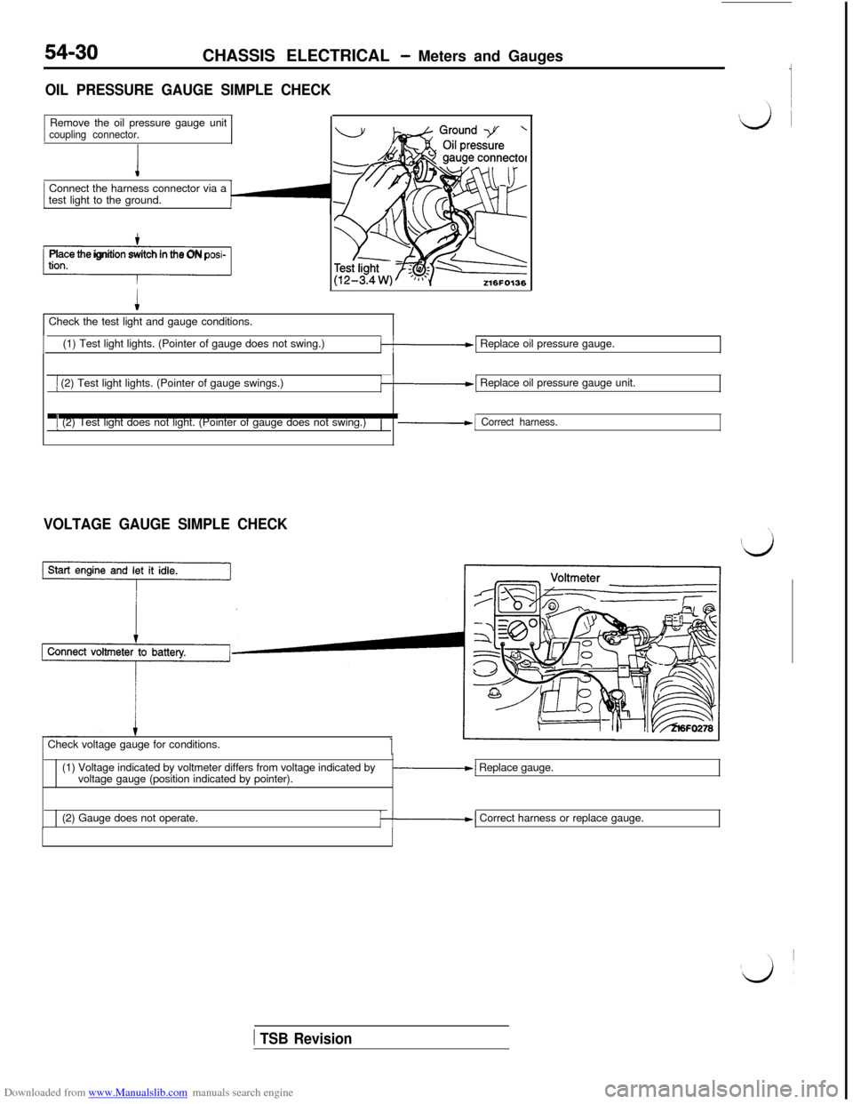
OIL PRESSURE GAUGE SIMPLE CHECKRemove the oil pressure gauge unit
coupling connector.Connect the harness connector via a
test light to the ground.
-1Place the ignition switch in the ON posi-Check the test light and gauge conditions.
(1) Test light lights. (Pointer of gauge does not swing.)
k-1 Replace oil pressure gauge.
1 (2) Test light lights. (Pointer of gauge swings.)k-1 Replace oil pressure gauge unit.
1 (2) Test light does not light. (Pointer of gauge does not swing.)/-1 Correct harness.
VOLTAGE GAUGE SIMPLE CHECKCheck voltage gauge for conditions.
(1) Voltage indicated by voltmeter differs from voltage indicated by
voltage gauge (position indicated by pointer).
-1 Replace gauge.
(2) Gauge does not operate.
/--I Correct harness or replace gauge.
1 TSB Revision
Page 527 of 738
Downloaded from www.Manualslib.com manuals search engine CHASSIS ELECTRICAL - Meters and Gauges54-31
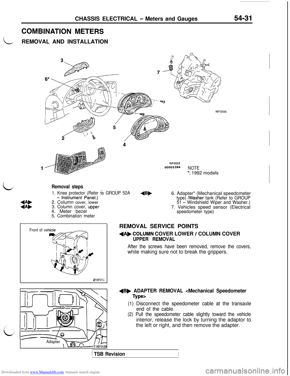
COMBINATION METERS
LREMOVAL AND INSTALLATION
76FO22200002364
NOTE
*: 1992 models
L/
:i:
- lnstiument PineI.)
2. Column cover, lower
3. Column cover, upper 1. Knee protector (Refer
G GROUP 52A4. Meter bezel
* ’5. Combination meter
Removal steps6. Adapter* (Mechanical speedometer
type) /Washer tank (Refer to GROUP
51 - Windshield Wiper and Washer.)7. Vehicles speed sensor (Electrical
Front of ve
219FOl;
speedometer type)REMOVAL SERVICE POINTS
dAbCOLUMN COVER LOWER / COLUMN COVER
UPPER REMOVAL
After the screws have been removed, remove the covers,while making sure not to break the grippers.
dB, ADAPTER REMOVAL
(1) Disconnect the speedometer cable at the transaxle
end of the cable.
(2) Pull the speedometer cable slightly toward the vehicleinterior, release the lock by turning the adaptor to
the left or right, and then remove the adapter.
Adapter-Y16FO129],
) TSB RevisionI
Page 531 of 738
Downloaded from www.Manualslib.com manuals search engine CHASSIS ELECTRICAL - Lighting System
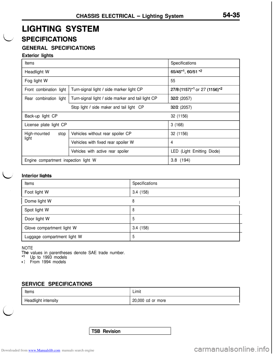
LIGHTING SYSTEM
54-35
L/ SPECIFICATIONSGENERAL SPECIFICATIONS
Exterior lights
ItemsSpecificationsHeadlight W
65/45*‘, 60151 *2Fog light W
55
Front combination light
Turn-signal light / side marker light CP27/8 (1157)” or 27 (1156)*2
Rear combination lightTurn-signal light / side marker and tail light CP32/2 (2057)
Stop light / side maker and tail lightCP32/2 (2057)
Back-up light CP
32 (1156)
License plate light CP3 (168)
High-mountedstop
Vehicles without rear spoiler CP32 (1156)
light
Vehicles with fixed rear spoiler W4
Vehicles with active rear spoiler
Engine compartment inspection light WLED (Light Emitting Diode)3.8 (194)
Interior
lights
ItemsFoot light WSpecifications
3.4 (158)
IDome light W8ISpot light W
8Door light W
5
Glove compartment light W
Luggage compartment light W3.4 (158)
5
NOTE
;he values in parentheses denote SAE trade number.
Up to 1993 models
l 2From 1994 modelsSERVICE SPECIFICATIONS
ItemsLimitI
Headlight intensity
I
20,000 cd or moreI
TSB Revision