light MITSUBISHI 3000GT 1992 2.G Workshop Manual
[x] Cancel search | Manufacturer: MITSUBISHI, Model Year: 1992, Model line: 3000GT, Model: MITSUBISHI 3000GT 1992 2.GPages: 738, PDF Size: 35.06 MB
Page 466 of 738
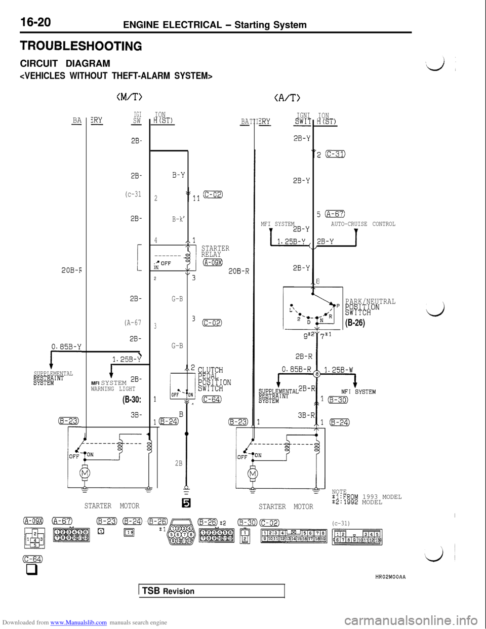
Downloaded from www.Manualslib.com manuals search engine 16-20ENGINE ELECTRICAL - Starting SystemTROUBLESHOOTING
CIRCUIT DIAGRAM
(M/T>(A/T>
IGISW-
2B-
2B-
(c-31
2B-
!
2B-
(A-67
2B-ION
HCST)IGNIZRYSWIT-
2B-Y
IONHCST)BAZRY--BA-TTI
B-1
2
B-k
4
-------;;OFF2
G-B
3
G-B
I
I
/\17rSTARTERRELAY
(A-09X)AL\I;20B-R
3.
,.;
,
8$J (c-64)
0I
2B-Y
5(A-67)
AUTO-CRUISE CONTROL
2B-Y 1
MFI SYSTEM
1 1.25y
2B-Y20B-F
3
PARK/NEUTRAL&~#ONij
(B-26)
g:27:1
i28-R
0.85B-Y
ISUPPLEMENTALgf;EEiINT
1.25B-y\
1MFI SYSTEM 2B-WARNING LIGHT
1iOF?-
lmB
2B
(B-30:
3B-(8-23)
rii------- ____
d
0
==
STARTER MOTOR
NOTE%l:FROM 1993 MODEL%2:1992 MODEL
I(c-31)
STARTER MOTOR
(c-64)q
HR02MOOAA
1 TSB Revision
Page 467 of 738
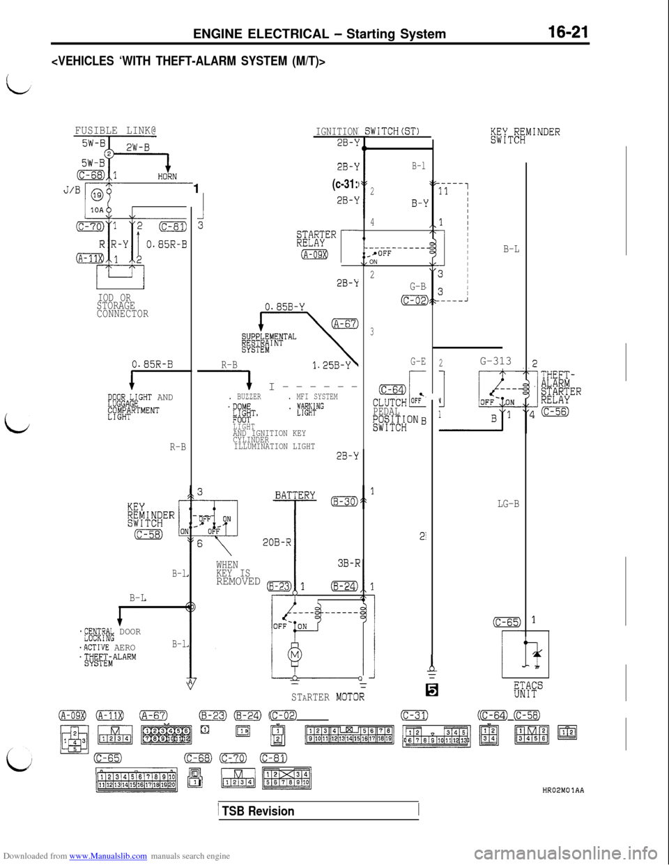
Downloaded from www.Manualslib.com manuals search engine ENGINE ELECTRICAL - Starting System16-21
FUSIBLE LINK@
zJ==%~,
IGNITION
2B-k
iWITCH
B-L
B-l
2
B-j
4
2B-k1
(c-31:
2B-kJ/Br
rwER
(A-OSXII-
----------SrOFFON
2
G-B
(c-02
3
G-E
PEDAL&~#,;~ONB
28-k
IOD ORSTORAGE
CONNECTOR0.85B-Y
R-B
1 I------. BUZZER. MFI SYSTEM.DOME#T,. fl@+NG
LIGHT
AND IGNITION KEY
CYLINDER
ILLUMINATION LIGHT
2G-3130.85R-B
1E;$gAb;GHT AND
EW';RTMENT
i
R-B2B-Y
3B-F
20B-R
WHEN
KEY IS
REMOVED (B-23:
r-
'TE
!
LG-B
21Q
MOTOR
B-l
B-L-
*;~F$K& DOOR
.ACTWE AEROB-l
4EHE;iALARM
(c-65)
r
d
6
I
ms
(c-31)(c-56) (c-58)(c-64)
STARTER
mf3t7)(c-02)
HR02MOlAA
1 TSB Revision
Page 468 of 738
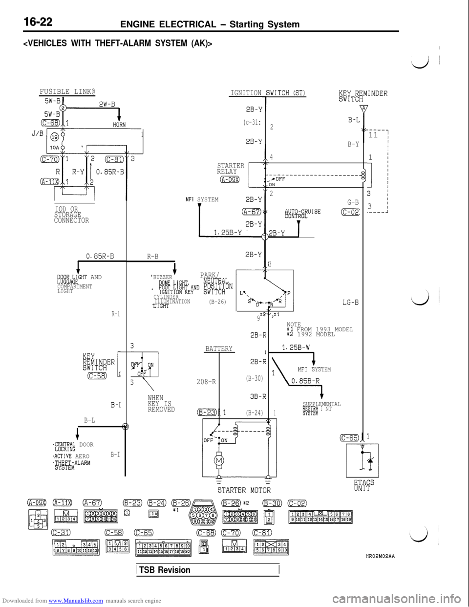
Downloaded from www.Manualslib.com manuals search engine 16-22ENGINE ELECTRICAL - Starting System
#d ~
FUSIBLE LINK@IGNITIONf
T2B-k
(c-31:
1
iWITCH (ST)
.----11 1II
I1
I
1 1
3 /3
I.----A 2
2B-Y
B-Y
4ISTARTER
RELAY
@liB
MFI SYSTEM2B-Y
--____----------------.-*OFFON
2
G-B
IOD OR
STORAGE
CONNECTOR32B~yg$!y”IsE (c-02:
O.a5R-BR-B2B-Y
eQsCIAk;GHT AND
COMPARTMENT
LIGHT
3
'BUZZERPARK/
. f~[f,\6[!?.+~~ [#~f#hI
CYLINDER
ILLUMINATION
tIGHT(B-26)
L’\2'D-'
9:2
r’”
,:1R-i
NOTEXl FROM 1993 MODEL:2 1992 MODEL
'l.25B-W
MFI SYSTEM
2B-R
BATTERY(
2B-R
208-R(B-30)
3B-R
(B-23)1(B-24)
SUPPLEMENTAL
1gEyL&E"i I NT
h
STARTER ~0~0: WHEN
KEY IS
REMOVED
B-1
B-L
$FRIW& DOOR
.ACTIVE AEROB-I
*TWF;~ALARM
HR02M02AA
1 TSB Revision
Page 497 of 738
Downloaded from www.Manualslib.com manuals search engine 54-1
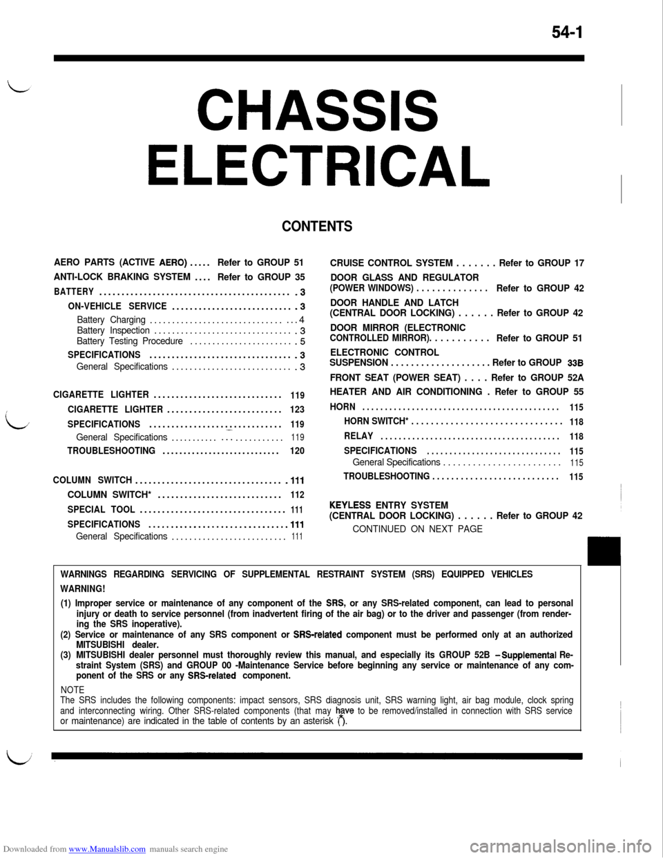
CHASSIS
ELECTRICAL
CONTENTS
AERO PARTS (ACTIVE AERO).....Refer to GROUP 51
ANTI-LOCK BRAKING SYSTEM....
Refer to GROUP 35
BATTERY...........................................-3
ON-VEHICLE SERVICE............................3
Battery Charging.................................4Battery Inspection................................3Battery Testing Procedure........................5
SPECIFICATIONS................................-3
General Specifications............................3
CIGARETTE LIGHTER.............................119
CIGARETTE LIGHTER..........................123
SPECIFICATIONS..............................
119
General Specifications............I...........119
TROUBLESHOOTING............................120
COLUMN SWITCH.................................
.lll
COLUMN SWITCH*............................112
SPECIAL TOOL.................................111
SPECIFICATIONS...............................111
General Specifications..........................111
CRUISE CONTROL SYSTEM . . . . . . . Refer to GROUP 17
DOOR GLASS AND REGULATOR
(POWER WINDOWS) . . . . . . . . . . . . . .Refer to GROUP 42
DOOR HANDLE AND LATCH
(CENTRAL DOOR LOCKING) . . . . . . Refer to GROUP 42
DOOR MIRROR (ELECTRONIC
CONTROLLED MIRROR). . . . . . . . . . .Refer to GROUP 51
ELECTRONIC CONTROL
SUSPENSION . . . . . . . . . . . . . . . . . . . . Refer to GROUP
338
FRONT SEAT (POWER SEAT) . . . . Refer to GROUP 52A
HEATER AND AIR CONDITIONING . Refer to GROUP 55
HORN. . . . . . . . . . . . . . . . . . . . . . . . . . . . . . . . . . . . . . . . . . . .
115
HORN SWITCH* . . . . . . . . . . . . . . . . . . . . . . . . . . . . . . .118
RELAY. . . . . . . . . . . . . . . . . . . . . . . . . . . . . . . . . . . . . . . .
118
SPECIFICATIONS. . . . . . . . . . . . . . . . . . . . . . . . . . . . . .
115
General Specifications . . . . . . . . . . . . . . . . . . . . . . . .115
TROUBLESHOOTING . . . . . . . . . . . . . . . . . . . . . . . . . . .115
KEYLESS ENTRY SYSTEM
(CENTRAL DOOR LOCKING) . . . . . . Refer to GROUP 42
CONTINUED ON NEXT PAGE
WARNINGS REGARDING SERVICING OF SUPPLEMENTAL RESTRAINT SYSTEM (SRS) EQUIPPED VEHICLES
WARNING!
(1) Improper service or maintenance of any component of the
SRS, or any SRS-related component, can lead to personal
injury or death to service personnel (from inadvertent firing of the air bag) or to the driver and passenger (from render-
ing the SRS inoperative).
(2) Service or maintenance of any SRS component or
SRS-related component must be performed only at an authorized
MITSUBISHI dealer.
(3)MITSUBISHI dealer personnel must thoroughly review this manual, and especially its GROUP 52B
TSupplemental Re-
straint System (SRS) and GROUP 00 -Maintenance Service before beginning any service or maintenance of any com-
ponent of the SRS or any
SRS-related component.
NOTE
The SRS includes the following components: impact sensors, SRS diagnosis unit, SRS warning light, air bag module, clock spring
and interconnecting wiring. Other SRS-related components (that may
h,a”” to be removed/installed in connection with SRS serviceor maintenance) are indicated in the table of contents by an asterisk ( ).
Page 498 of 738
Downloaded from www.Manualslib.com manuals search engine 54-2
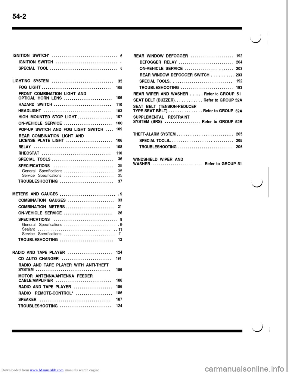
IGNITION SWITCH*..................................6
IGNITION SWITCH.................................
SPECIAL TOOL...................................6
LIGHTING SYSTEM................................35
FOG LIGHT....................................105
FRONT COMBINATION LIGHT AND
OPTICAL HORN LENS.........................106
HAZARD SWITCH..............................
110
HEADLIGHT...................................103
HIGH MOUNTED STOP LIGHT..................107
ON-VEHICLE SERVICE.........................100
POP-UP SWITCH AND FOG LIGHT SWITCH....109
REAR COMBINATION LIGHT AND
LICENSE PLATE LIGHT........................106
RELAY........................................108
RHEOSTAT....................................
110
SPECIAL TOOLS................................36
SPECIFICATIONS...............................
35
General Specifications..........................35Service Specifications..........................35
TROUBLESHOOTING............................37
METERS AND GAUGES..............................9
COMBINATION GAUGES........................33
COMBINATION METERS.........................31
ON-VEHICLE SERVICE...........................26
SPECIFICATIONS.................................
9
General Specifications............................9Sealant........................................ll
Service Specifications...........................11
TROUBLESHOOTING............................12
RADIO AND TAPE PLAYER.......................124
CD AUTO CHANGER..........................191
RADIO AND TAPE PLAYER WITH ANTI-THEFTSYSTEM.......................................156
MOTOR ANTENNA/ANTENNA FEEDERCABLE/AMPLIFIER.............................188
RADIO AND TAPE PLAYER....................186
RADIO REMOTE-CONTROL*...................186
SPEAKER.....................................
187
TROUBLESHOOTING...........................
124
REAR WINDOW DEFOGGER. . . . . . . . . . . . . . . . . . . . . .192
DEFOGGER RELAY. . . . . . . . . . . . . . . . . . . . . . . . . . . .204
ON-VEHICLE SERVICE. . . . . . . . . . . . . . . . . ~ ~. . . . . .203
REAR WINDOW DEFOGGER SWITCH . . . . . . -. . . 203
SPECIAL TOOLS.. . . s.. . . . . . . . . . . . . . . . . . . . . . . . .192
TROUBLESHOOTING
. . . . . . . . . . . . . . . . . . . . . . . . . . .193
REAR WIPER AND WASHER . . ~ *. . Refer to GROUP 51
SEAT BELT (BUZZER). . . . . . . . . . . . Refer to GROUP 52A
SEAT BELT (TENSION-REDUCERTYPE SEAT BELT) . . . . . . . . . . . . . . . Refer to GROUP 52A
SUPPLEMENTAL RESTRAINTSYSTEM (SRS)..-...............Refer to GROUP 52B
THEFT-ALARM SYSTEM . . . . . . . . . . . . . . . . . e . . . . . m.. s205
SPECIAL TOOLS.. . . . . . . . . . . . . . . . . . . .
m . . . . . . . .e205
TROUBLESHOOTING . . . . . . . . . . . . . . . . . . . . . . . . . . .206
WINDSHIELD WIPER ANDWASHER. . . . . . . . . . . . . . . . . . . . . ~. . .Refer to GROUP 51
Page 501 of 738
Downloaded from www.Manualslib.com manuals search engine CHASSIS ELECTRICAL - Battery54-5BATTERY TESTING PROCEDURE
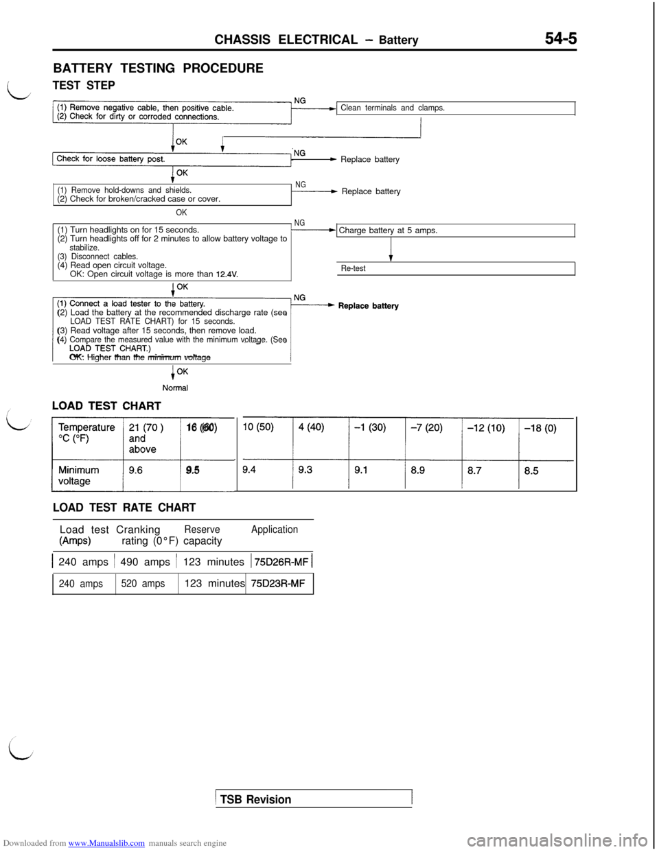
LTEST STEP
Clean terminals and clamps.
- Replace battery
(1) Remove hold-downs and shields.(2) Check for broken/cracked case or cover.
OK
NG- Replace battery
(1) Turn headlights on for 15 seconds.
NG(2) Turn headlights off for 2 minutes to allow battery voltage to- Charge battery at 5 amps.
stabilize.
(3) Disconnect cables.(4) Read open circuit voltage.
IOK: Open circuit voltage is more than
12.4V.Re-test(2) Load the battery at the recommended discharge rate (see
LOAD TEST RATE CHART) for 15 seconds.(3) Read voltage after 15 seconds, then remove load.
(4) Compare the measured value with the minimum voltage. (SeeOK: Higher than the minimum voltage
i
Normal
LL16 (60)
9.5
LOAD TEST RATE CHARTLoad test Cranking
Reserve
W-w)rating (0°F) capacity
Application
1 240 amps / 490 amps / 123 minutes 1 75D26R-MF 1
240 amps520 amps123 minutes 75D23R-MF
1 TSB Revision1
Page 504 of 738
Downloaded from www.Manualslib.com manuals search engine 54-8CHASSIS ELECTRICAL - Ignition Switch
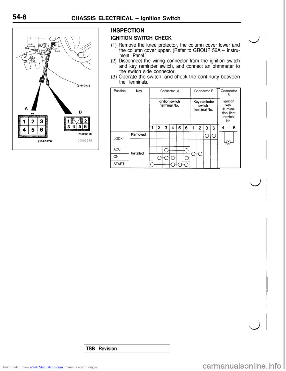
216AO57000002296INSPECTION
IGNITION SWITCH CHECK
(1) Remove the knee protector, the column cover lower andd’
the column cover upper. (Refer to GROUP 52A - Instru-
ment Panel.)
(2) Disconnect the wiring connector from the ignition switch
and key reminder switch, and connect an ohmmeter to
the switch side connector.(3) Operate the switch, and check the continuity between
the terminals.
PositionKeyConnector AConnector B
LOCK
ACC
ON
START
ConnectorB
ignitionkey
illumina-
tion light
terminal
No.
415
LJ
TSB Revision
Page 506 of 738
Downloaded from www.Manualslib.com manuals search engine 54-I 0CHASSIS ELECTRICAL - Meters and Gauges
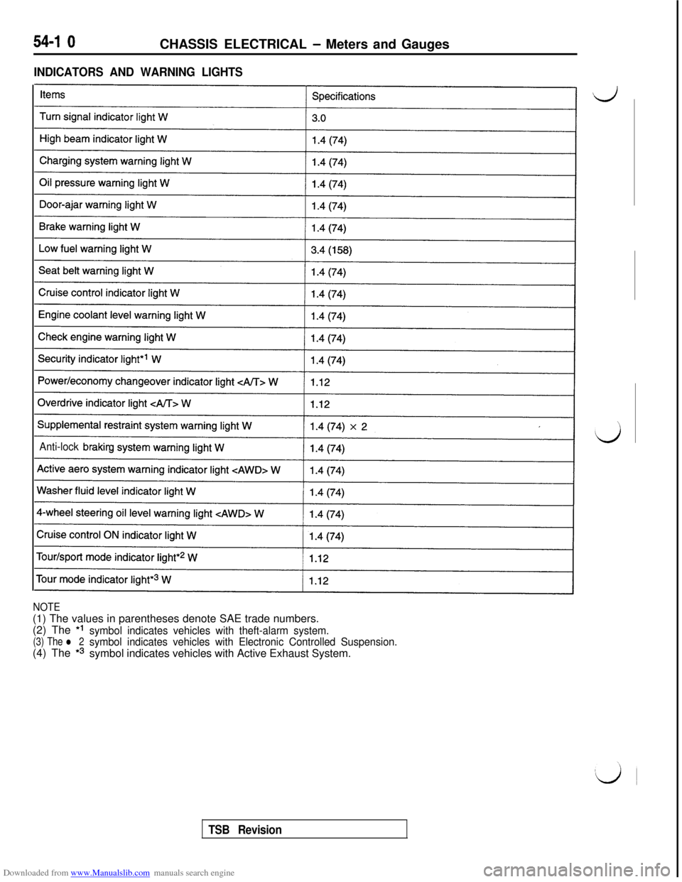
INDICATORS AND WARNING LIGHTS
Anti-lock brakin
NOTE(1) The values in parentheses denote SAE trade numbers.
(2) The *I
(3) The l 2symbol indicates vehicles with theft-alarm system.(4) The
*3
symbol indicates vehicles with Electronic Controlled Suspension.symbol indicates vehicles with Active Exhaust System.
TSB Revision
Page 512 of 738
Downloaded from www.Manualslib.com manuals search engine 54-16CHASSIS ELECTRICAL - Meters and Gauges
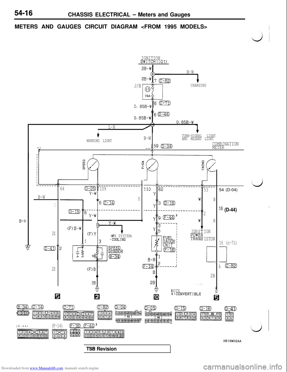
METERS AND GAUGES CIRCUIT DIAGRAM
IGNITIONSWITCH(IG1)
B-W
J/B
CHARGING
\,
0. 85B-W“' -
tO.B5B-Ws(D-44)
B-1
O.B5B-W
L-RI
--r
tB-WTURN-SIGNAL LIGHT
WARNING LIGHTAND HAZARD LIGHT
--,,59 (D-04)COMBINATION
METER
/\
B-W
I
2E
2E(F:
64(D-C
Y
\L
-W
\:
---.
-W
13
)Y
)B '
0
2Bn=
-------------____109
ES(c-14)
--------------___
.MFI SYSTEMIGN:
R3
(B-34) (c-14)(c-71)
m m m z ~~~~5&4
60161(6216~64165166167(D-44)
(F-14)(Fm (ml'
NOTE4::CONVERTIBLE
-..I
-----53
B
2
B
ION
ISTOR
i
2B
‘d54 (D-04)
I6 (D-44)I
16 (c-71)
1
j(c-82)
TSB Revision
Page 514 of 738
Downloaded from www.Manualslib.com manuals search engine 54-18CHASSIS ELECTRICAL - Meters and Gauges
OPERATION
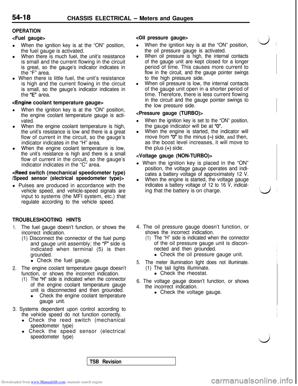
When the ignition key is at the “ON” position,the fuel gauge is activated.
l
When there is much fuel, the unit’s resistanceis small and the current flowing in the circuit
is great, so the gauge’s indicator indicates inthe “F” area.
l When there is little fuel, the unit’s resistance
is high and the current flowing in the circuit
is small, so the gauge’s indicator indicates inthe
“E” area.
lWhen the ignition key is at the “ON” position,
the engine coolant temperature gauge is acti-
vated.l
When the engine coolant temperature is high,
the unit’s resistance is low and there is a greatflow of current in the circuit, so the gauge’s
indicator indicates in the “H” area.
l
When the engine coolant temperature is low,
the unit’s resistance is high and there is a smallflow of current in the circuit, so the gauge’s
indicator indicates in the “C” area.
vehicle speed, and vehicle-speed signals areinput to systems (the MFI system, etc.) that
regulate according to the vehicle speed.
TROUBLESHOOTING HINTS
1.The fuel gauge doesn’t function, or shows the
incorrect indication.
(1) Disconnect the connector of the fuel pumpand gauge unit assembly; the ‘F” side is
indicated when terminal (5) is then
grounded.l Check the fuel gauge.
2.The engine coolant temperature gauge doesn’t
function, or shows the incorrect indication.
(1)The “l-l” side is indicated when the connector
of the engine coolant temperature gauge
unit is disconnected and then grounded.l
Check the engine coolant temperature
gauge unit.
3. Systems dependent upon control according to
the vehicle speed do not function correctly.l Check the reed switch (mechanical
speedometer type)l Check the speed sensor (electrical
speedometer type)
coil pressure gauge>l
When the ignition key is at the “ON” position,
the oil pressure gauge is activated.
lWhen oil pressure is high, the internal contacts
of the gauge unit are kept closed for a longerperiod of time. This causes more current to
flow in the circuit, and the gauge pointer swings
to the high pressure side.
lWhen oil pressure is low, the internal contactsof the gauge unit open in a shorter period of
time. Therefore, there is less current flowing
in the circuit and the gauge pointer swings to
the low pressure side.
lWhen the ignition key is set to the “ON” position,the gauge indicator will be at
“0”.l
When the engine is started, the indicator will
move from
“0” to the minus (-) side, and then,as the boost level increases, it will move to
the plus
(+) side.
position, the voltage gauge operates and indi-
cates a battery voltage of approximately 12 V.l
When the engine is started, the voltage gauge
indicates a battery voltage of 12 to 16 V, indicat-ing that the battery is on charge.
4. The oil pressure gauge doesn’t function, or
shows the incorrect indication.
(1)The “H” side is indicated when the connectorof the oil pressure gauge unit is discon-
nected and then grounded.l Check the oil pressure gauge unit.
5.The meter illumination light does not illuminate.
(1) The tail lights illuminate.l Check the rheostat.
6. The voltage gauge doesn’t function, or shows
the incorrect indication.l Check the voltage gauge.
TSB Revision