MITSUBISHI 3000GT 1992 2.G Workshop Manual
3000GT 1992 2.G
MITSUBISHI
MITSUBISHI
https://www.carmanualsonline.info/img/19/7561/w960_7561-0.png
MITSUBISHI 3000GT 1992 2.G Workshop Manual
Trending: steering wheel adjustment, window, high beam, coolant level, instrument panel, flat tire, cooling
Page 161 of 738
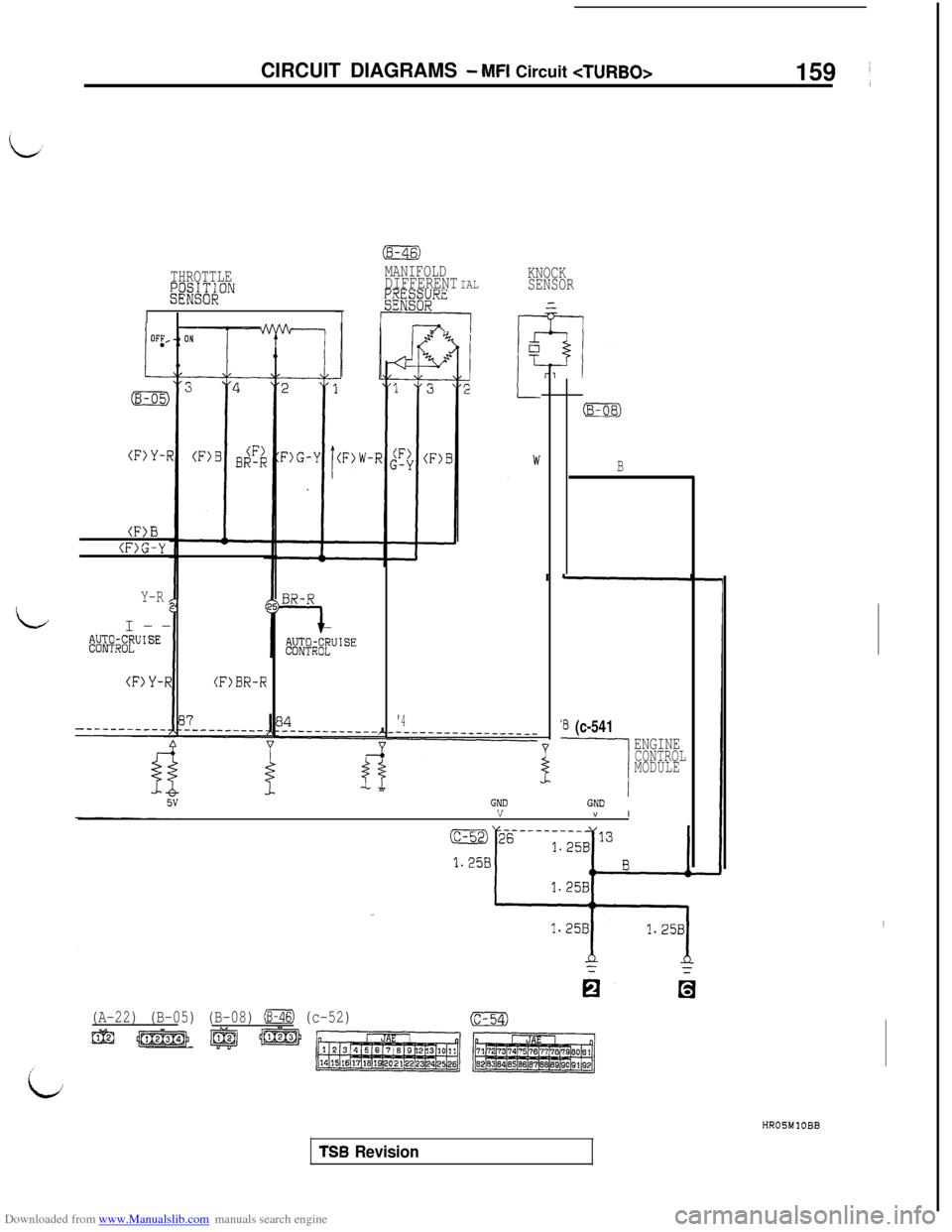
Downloaded from www.Manualslib.com manuals search engine CIRCUIT DIAGRAMS - MFI Circuit
159 ’
THROTTLEI%%;~""
(F>Y-R
B
(F>G-Y
Y-R
LI--@$;$$UISE
(F>Y-R(F)BR-R
MANIFOLDDIFFERENTIALp&RE
' ----I
'4
KNOCK
SENSORGND
V
(B-OB)
B
‘8 (c-541
---I
ENGINECONTROL
MODULE
GNDv I
(A-22) (B-05) (B-08) (B-46) (c-52)
m !jp&Tj) @ jlTEE#
(c-54)
HROSMlOBB
TSB Revision
Page 162 of 738
Downloaded from www.Manualslib.com manuals search engine CIRCUIT DIAGRAMS - MFI Circuit
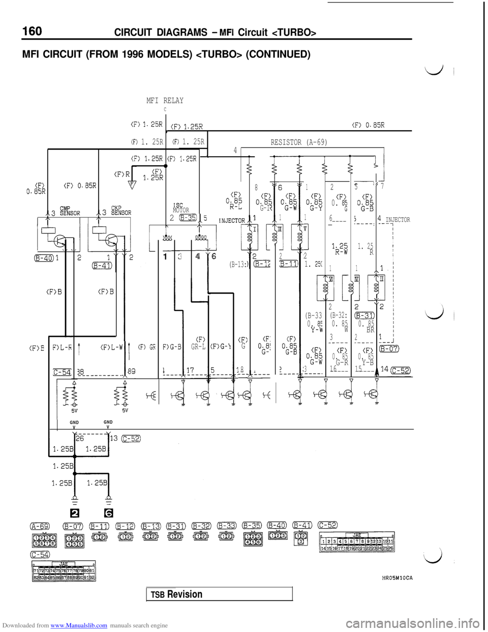
MFI CIRCUIT (FROM 1996 MODELS) (CONTINUED)
MFI RELAY
C
(F) 'I. 25R(F) 1. 25R(F) 0.85R1
(F) 1. 25R(F) 1. 25RRESISTOR (A-69)
4
(F> 1.25R (F) ?.25R+0(F)1.25R(F)0.05R(F) 0.85R
(F)
,,3 %%SOR,,3 %SORISCMOTOR“kSL”
/\I\2 0,,5INJECTOR/x3R,\7r,1
2
(F)0. 82
6_----
:5
(F)
O$g
5.----:7
(B-40)1
.
l!b
--1
:3
(F>B
L4 6
(B-13:
8
o.‘El
G-I
1
[
1[)
:B-l;
3
(F)
“i;“;
1
II
II
2pi-J
1
CF>
“;;“$
1
v
I
2
1. 25C
1. 25R
3 INJECTOR---7III
I
II1
I
11
(B-33
0.
85Y-W
(F>EF)L-kt(F)L-‘!I
‘I
!_ 8!
(F) GEDG-I(F)GR-L(F)G-\I(F:G(F:
OS”’
(F)
OS”;
:c-EL- _______ _8L-.-
1I----
iE
(F>
Ok”;
3----.
m
I[
2
(B-32:
0. 85W3_----
(F)
0. 85
G-R16-----
m
I[
&
0. 85BR2_----
(F>0. 85Y-B15-----
ll
(
6
I\77
b1L\I
/
A-
lGNDGND
VV
HROSMlOCA
TSB Revision
Page 163 of 738
Downloaded from www.Manualslib.com manuals search engine CIRCUIT DIAGRAMS - MFI Circuit 161 i
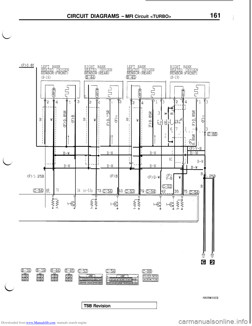
LEFT BANK
HEATED OXYGENRIGHT BANK
SENSORCFRONT)HEATED OXYGENLEFT BANKSENSORCREAR)HEATED OXYGENRIGHT BANKSENSORCREAR)HEATED OXYGEN
(B-16)(8-44)(8-45)SENSORCFRONT)
(B-19)
*; \,J L-
1
‘5
r
5IImmIId2BI
2"8III/.I//II/rI
B-WII
I
JL
3
rIIII
B/III1/IIIII
c
34 (c-53:
IF--l
B-W
76
'4L “'1 "3--7.-J
I%co m
h'c;t:
Bv
2-8 3- - - - -_ _“(c-88).- 3%
' F?I voI
/ (F)Y-B
+ B-WII-JB-W
!I
L-
B-W
(F>B
I Ik ”'1 "3$'2--_
--_3
3m2
CL&L, ;2izv vv
6 7
---
*I3
&
r--‘
-+
I
B-W/
WI---B-W
L
t
(F11.258
(c-54)HROJMlOCB
TSB Revision
Page 164 of 738
Downloaded from www.Manualslib.com manuals search engine CIRCUIT DIAGRAMS - MFI Circuit
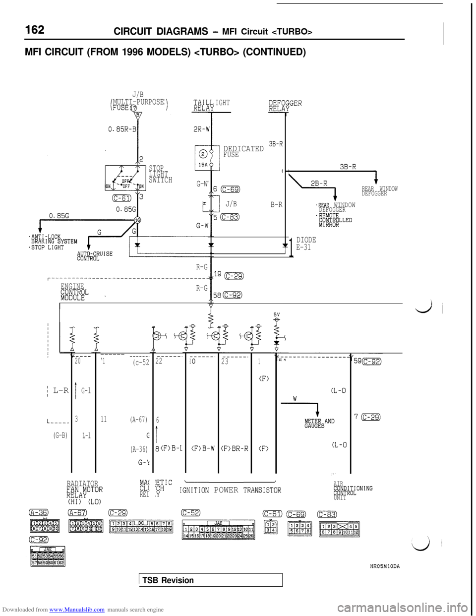
MFI CIRCUIT (FROM 1996 MODELS) (CONTINUED)
J/B
(MULTI-PURPOSEFUSE@IGHT/GER
I3B-R
2B-R
\
REAR WINDOW
DEFOGGER
.REAR WINDOWDEFOGGER.REMOTE;p$$;;LLED
1
DIODEE-31
I
DEDICATED 3B-RFUSE
I
50
IJ/BB-R
5(c-83)
STOP
LIGHT
SWITCHG-Wr
580
R-G
r--------------------------------------~
ENGINE
ggp ~R-G
d i
---_20
IG-l
3
L-l
------ ------.‘1(c-52
------.22
6
I
8(F>B-1
------.------.IO231
(F>
(F)B-W(F>BR-R(F)
/ L-R(L-0
--Y!4;;4~SAND
(L-0
11(A-67)
c
(A-36)
G-b
L----_
(G-B)
RADIATOR;~~A~OTORFEREI(HI) (LO)iwc
AIR
.YIGiITION POWER TRANS&R~Cl~~l~~ON’NG
UNIT
HR05MlODA
1 TSB Revision
Page 165 of 738
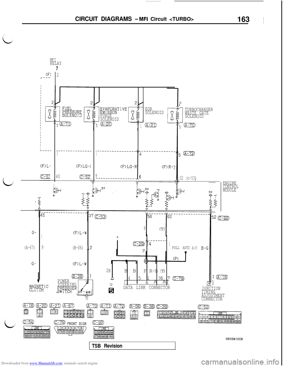
Downloaded from www.Manualslib.com manuals search engine CIRCUIT DIAGRAMS - MFI Circuit 163 ~
MFIRELAY
(F:r---’
IIIIII/IIII-----
(F>L-
G-
(A-67)
G-
7
2
_-----------___3
(F>LG-1
40E
/2(
I
g9g;fiTI~~/\
PURGESOLENOID
j(A-20)1
EGR
SOLENOID
_____-___-______ _______~______14
i
(F)LG-R(F)R-'
9_____-____-__---6
PV :
1
I
TURBOCHARGER
WASTE GATE
SOLENOID
32 (c-53)
o+
I(F)L-'h
9(B-06)
(F)L-W
,,2
,,l
POWER
STEERING
g;y?;;ER
P
AI _-----,cc-29)“41FULL AUTO
2BB BP R-B (Y)
4n5 1167mA A A]
DATA LINK CONNECTOR
A/C
IGNITIONTIMING
ADJUSTMENT
CONNECTOR
ENGINE
CONTROL
MODULE
l(A-18)
1
TSB Revision
Page 166 of 738
Downloaded from www.Manualslib.com manuals search engine CIRCUIT DIAGRAMS - MFI Circuit
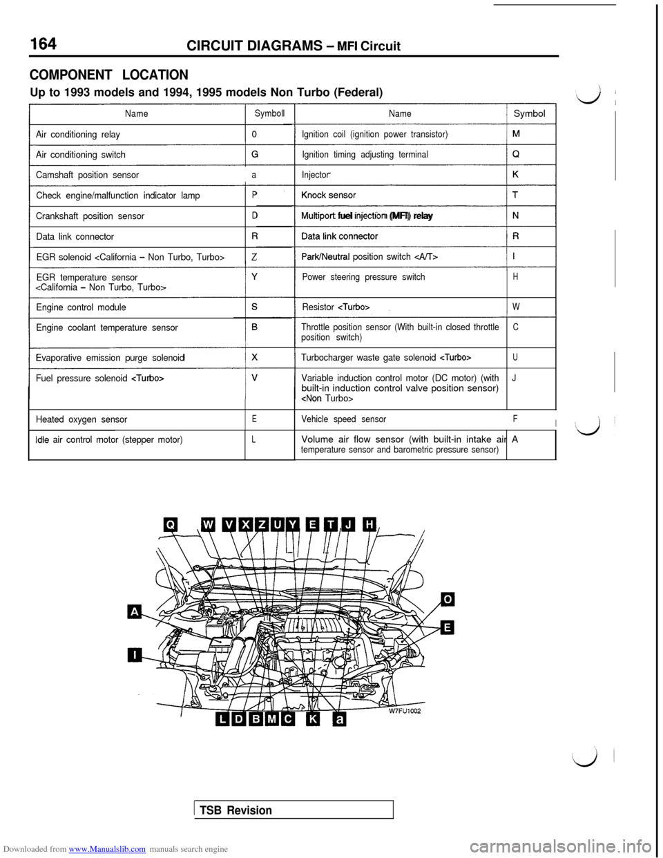
COMPONENT LOCATIONUp to 1993 models and 1994, 1995 models Non Turbo (Federal)
NameSymbol
Air conditioning relay0
Air conditioning switch
Camshaft position sensor
a
Check engine/malfunction indicator lampP
Crankshaft position sensorD
Data link connectorR
EGR solenoid Z
EGR temperature sensor
Engine control module
Engine coolant temperature sensor
Evaporative emission purge solenoid
Fuel pressure solenoid
Heated oxygen sensorE
idle air control motor (stepper motor)L
Name/ Symbol
Ignition coil (ignition power transistor)
Ignition timing adjusting terminal
Injector
(1
Multrport fuel rnjectron (MFI) relay
ParWNeutral position switch c&T>
Power steering pressure switchH
Resistor W
Throttle position sensor (With built-in closed throttleCposition switch)
Turbocharger waste gate solenoid U
Variable induction control motor (DC motor) (withJbuilt-in induction control valve position sensor)
Vehicle speed sensorFIVolume air flow sensor (with built-in intake air A
temperature sensor and barometric pressure sensor)
1 TSB Revision
Page 167 of 738
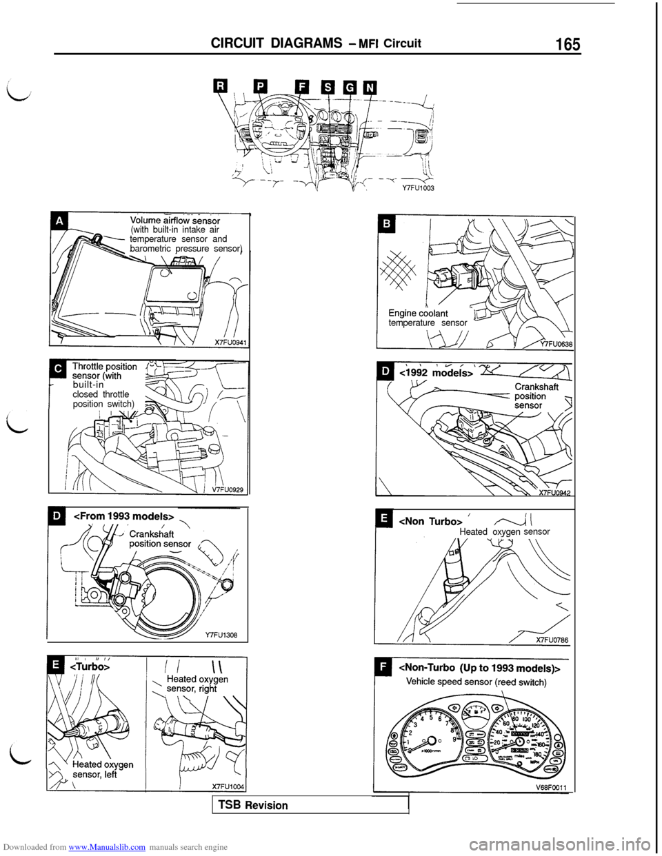
Downloaded from www.Manualslib.com manuals search engine CIRCUIT DIAGRAMS - MFI Circuit165
-x- --q-Y7FU1003
Volume &flo~‘.&&sor(with built-in intake air
temperature sensor and
barometric pressure sensor)
temperature sensor
Pbuilt-in
I
closed throttle
position switch)
IP--l IHeated oxygensensor
TSB Revision
Page 168 of 738
Downloaded from www.Manualslib.com manuals search engine CIRCUIT DIAGRAMS - MFI Circuit
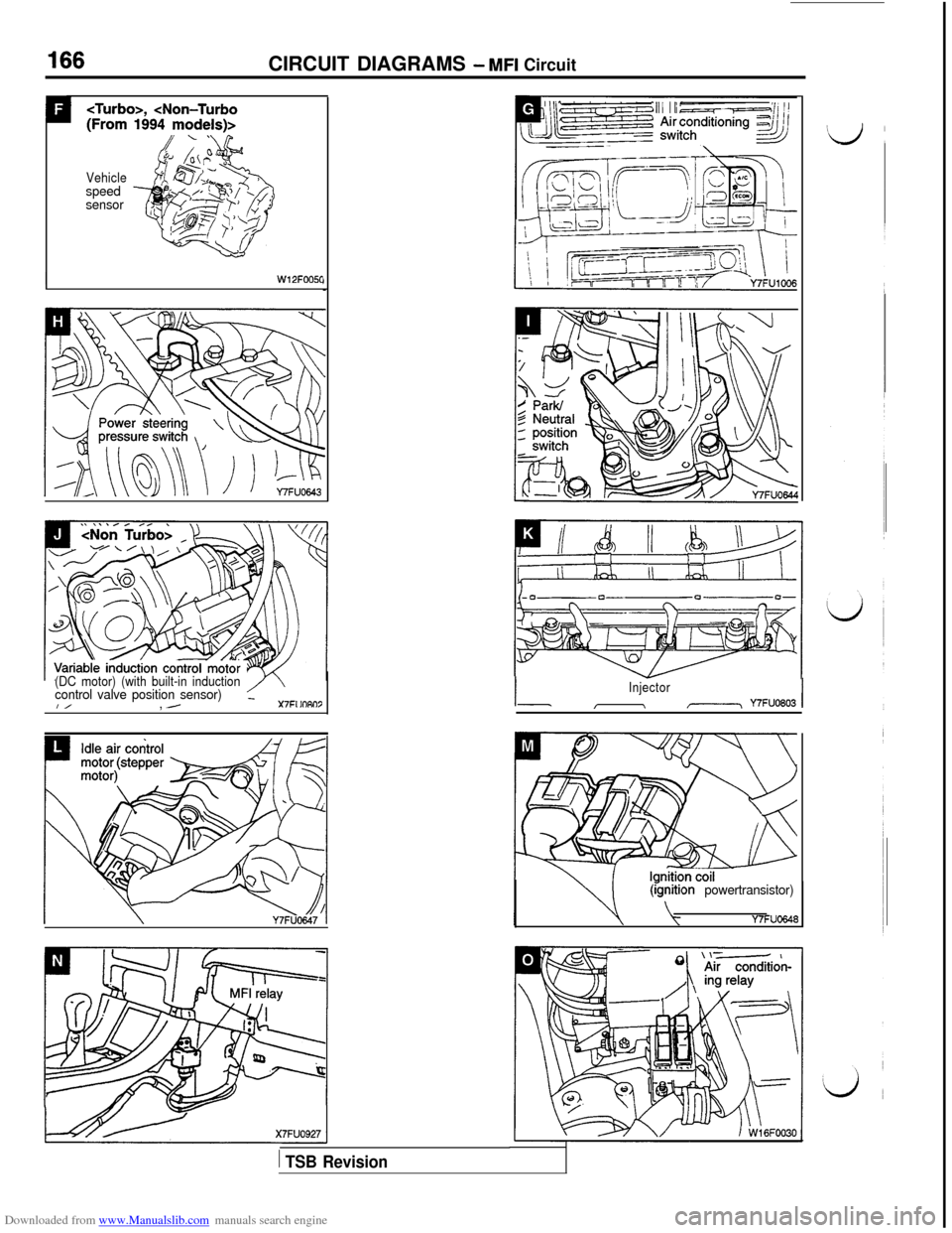
,
Vehiclespeed
sensor
IW12FOOSC
(DC motor) (with built-in inductioncontrol valve position sensor)_I/, ./X7FI lOAI-Injector
I\,-\ Y7FUO803I
(rgnition powertransistor)
Y7FUO648
1 TSB Revision
Page 169 of 738
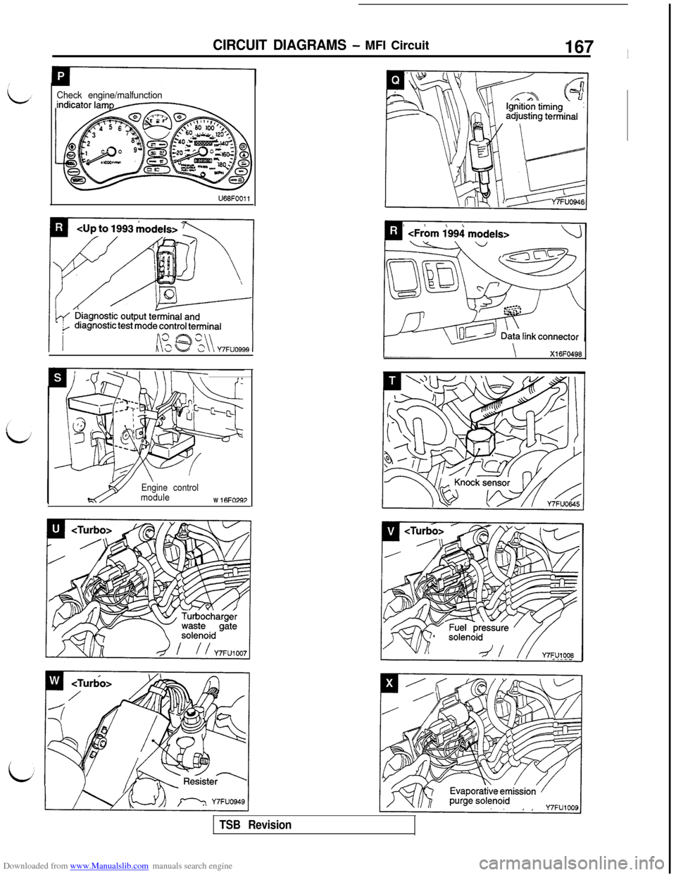
Downloaded from www.Manualslib.com manuals search engine CIRCUIT DIAGRAMS - MFI Circuit167 ~
Check engine/malfunction
Lki @ %\\ Y7FUO999 1
\l-T-T-. .
Engine control
moduleW
16FO297
Xl 6FO498
TSB Revision
Page 170 of 738
Downloaded from www.Manualslib.com manuals search engine CIRCUIT DIAGRAMS - MFI Circuit
\’\
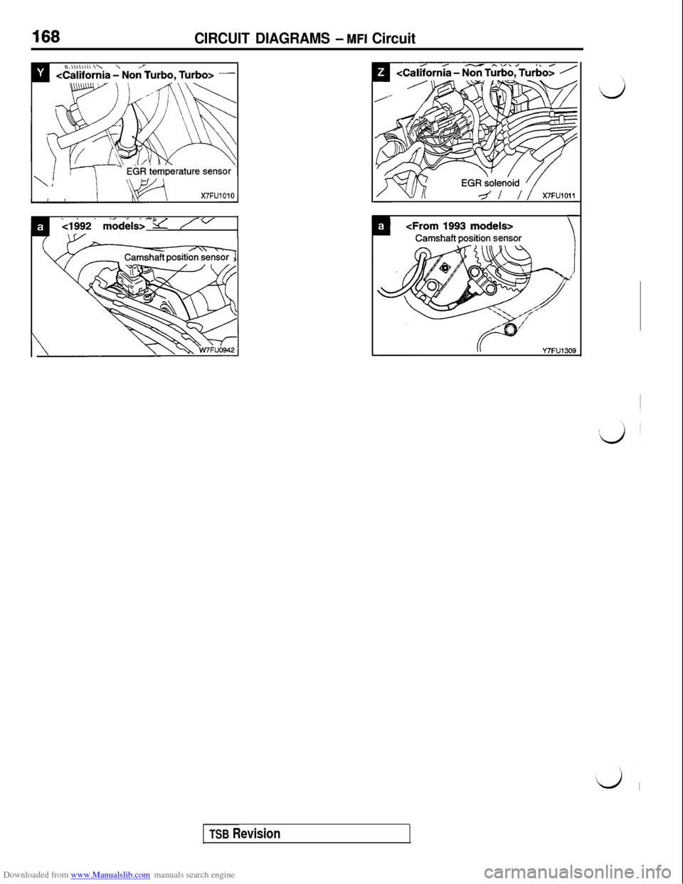
X7FUlOlO
~ ./ ,21492 model&-v yv\ r/
\
Y7FU1309
TSB Revision
Trending: horn, engine coolant, warning light, remote start, engine oil capacity, high beam, lumbar support
