check engine MITSUBISHI 3000GT 1992 2.G User Guide
[x] Cancel search | Manufacturer: MITSUBISHI, Model Year: 1992, Model line: 3000GT, Model: MITSUBISHI 3000GT 1992 2.GPages: 738, PDF Size: 35.06 MB
Page 40 of 738
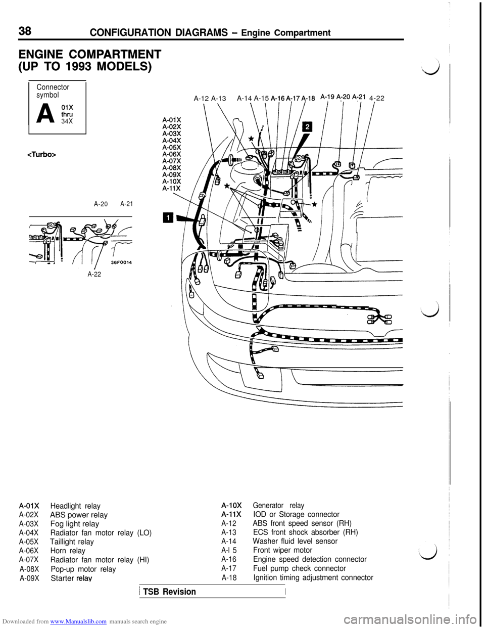
Downloaded from www.Manualslib.com manuals search engine 38CONFIGURATION DIAGRAMS - Engine Compartment
ENGINE COMPARTMENT
(UP TO 1993 MODELS)
Connector
symbol
A
01xthru
34X
A-20A-21
A-22
A-01X
A-02X
A-03X
A-04X
A-05X
A-06X
A-07X
A-08X
A-09XHeadlight relayABS power relay
Fog light relay
Radiator fan motor relay (LO)
Taillight relay
Horn relay
Radiator fan motor relay (HI)
Pop-up motor relayStarter
relavA-12 A-13A-14 A-15 A-16A:174-18
A-79 q-20 A:21 4-22
A-10X
A-11X
A-12
A-13
A-14
A-l 5
A-16
A-17
A-18Generator relayIOD or Storage connector
ABS front speed sensor (RH)
ECS front shock absorber (RH)
Washer fluid level sensor
Front wiper motor
Engine speed detection connector
Fuel pump check connector
Ignition timing adjustment connector
1 TSB RevisionI
Page 44 of 738
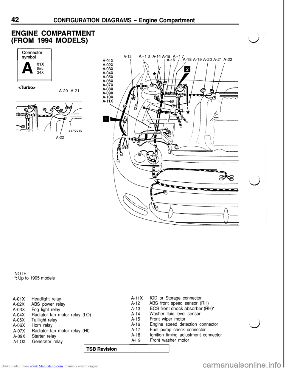
Downloaded from www.Manualslib.com manuals search engine 42CONFIGURATION DIAGRAMS - Engine Compartment
ENGINE COMPARTMENT
(FROM 1994 MODELS)
A01xthru
34X
A-22
NOTE*: Up to 1995 models
A-01X
A-02X
A-03X
A-04X
A-05X
A-06X
A-07X
A-09X
A-l OX
A-12A-13 A-14A-15 A-17A-01X!i\1 A-16 /A-18 A-19 A-20 A-21 A-22/I
Headlight relay
ABS power relay
Fog light relay
Radiator fan motor relay (LO)
Taillight relay
Horn relay
Radiator fan motor relay (HI)
Starter relay
Generator relayA-11XIOD or Storage connector
A-12ABS front speed sensor (RH)
A-13ECS front shock absorber (RH)*
A-14
Washer fluid level sensor
A-15Front wiper motor
A-16Engine speed detection connector
A-17Fuel pump check connector
A-18Ignition timing adjustment connector
A-l 9Front washer motorTSB
Revision
Page 111 of 738
Downloaded from www.Manualslib.com manuals search engine CIRCUIT DIAGRAMS - MFI Circuit
109 ~
IGPSW1-
2B
“#
-W
13SA
-W
-W
I
-W
;
i
IONH(IG1)
I
MFIRELD
-L
--o
-L
.R
,
R
-,:f
L
AY7
40
Ll(c-34)
3
]
FUELPUMP
(F-16)
17 m
\
2
J/B
1.250
)I
‘6 (c-71)
:smB-L0.85B-
0.85B-FUEL PUMPCHECKCONNECTOR 1.25B-
B-
59 (D-04)
I
COMBINATION
METER
)
1.25B-r-------.
I
lcD-03)
R
Ij 1.25B-
ZTER)
G-3
&
7
1
I
3c
G-F
(c-54):.
(c-53):2
BM
B
+5
3
0
3
n
/I1. 25:I/Y-WL--------
1. 251
ENGINE
CONTROL
MODULE
21
-.NOTE:l:FEDERAL:2:CALIFORNIA
I
M02AB
1 TSB Revision
Page 127 of 738
Downloaded from www.Manualslib.com manuals search engine CIRCUIT DIAGRAMS - MFI Circuit
IGNITIONSWITCH(IG1)
\,\I
5\IS(c-71)
-___-_---__
WARNING WARNING
LIGHT LIGHT
/
(F>1.25B-W(F>1.25B-W
G-I G-I
IGNITION IGNITION
G-R
1.25B-
,6 (D-44)1.25B-
FUEL PUMP
CHECK
CONNECTOR 1.25B-
tTURN-SIGNAL LIGHT
AND HAZARD LIGHT
59 (D-04)
COMBINATIONMETER1.25B-
7------ ------
COMBINATION
&%O,METE,:Y-W
I
6m_-_____-__-
Y-W
OSic-54)
r--------
.25B-1
1.25E
.25E
2B
tiF1IELAY7
g(c-34)
3
3
FUEL
PUMP
(F-16)
HR05M03AB
TSB Revision
Page 135 of 738
Downloaded from www.Manualslib.com manuals search engine CIRCUIT DIAGRAMS - MFI Circuit
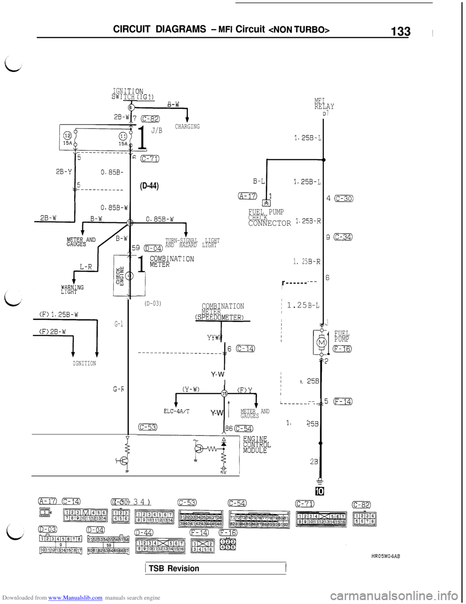
IGNSW1
28.
ITI1TCH
a:6
WI
2B-Y(
5
t
(D-44)1.25B-L--------___
(D-03)ICOMBINATION
METER/ 1.25B-L
(F)1.25B-W/
G-lliiiioojllliR:1IIIY-WI
t
I
----~~--~-----------_6m
IGNITIONY-W
I
/II1. :25B
G-h(Y-W)$, (F)Y/I+JI
,
L--------,,E
ELC-4A/TY-WMETER AND
GAUGES
(c-53)35B
------libel l. :0
2B
(IGl)B-W
1
J/BCHARGING
1.25B-L
FUEL PUMP0.85B-wCHECKCONNECTOR 1.25B-1i
TURN-SIGNAL LIGHT
g(D-04)AND HAZARD LIGHT
1
;;y;&NATION1. 25'B-R
-I
t.--r------I
MFIRELAYII7
4ic-30)
g(c-34)
3
1
FUEL
PUMP
m
)
j(F-14)
oFm (c-14)Cc-30)(c-34)(c-53)(c-54)(c-71)(c-82)
HR05M04AB
1 TSB Revision
Page 166 of 738
Downloaded from www.Manualslib.com manuals search engine CIRCUIT DIAGRAMS - MFI Circuit
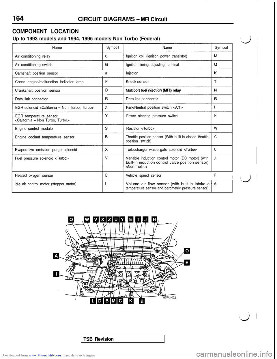
COMPONENT LOCATIONUp to 1993 models and 1994, 1995 models Non Turbo (Federal)
NameSymbol
Air conditioning relay0
Air conditioning switch
Camshaft position sensor
a
Check engine/malfunction indicator lampP
Crankshaft position sensorD
Data link connectorR
EGR solenoid
EGR temperature sensor
Engine control module
Engine coolant temperature sensor
Evaporative emission purge solenoid
Fuel pressure solenoid
Heated oxygen sensorE
idle air control motor (stepper motor)L
Name/ Symbol
Ignition coil (ignition power transistor)
Ignition timing adjusting terminal
Injector
(1
Multrport fuel rnjectron (MFI) relay
ParWNeutral position switch c&T>
Power steering pressure switchH
Resistor
Throttle position sensor (With built-in closed throttleCposition switch)
Turbocharger waste gate solenoid
Variable induction control motor (DC motor) (withJbuilt-in induction control valve position sensor)
Vehicle speed sensorFIVolume air flow sensor (with built-in intake air A
temperature sensor and barometric pressure sensor)
1 TSB Revision
Page 169 of 738
Downloaded from www.Manualslib.com manuals search engine CIRCUIT DIAGRAMS - MFI Circuit167 ~
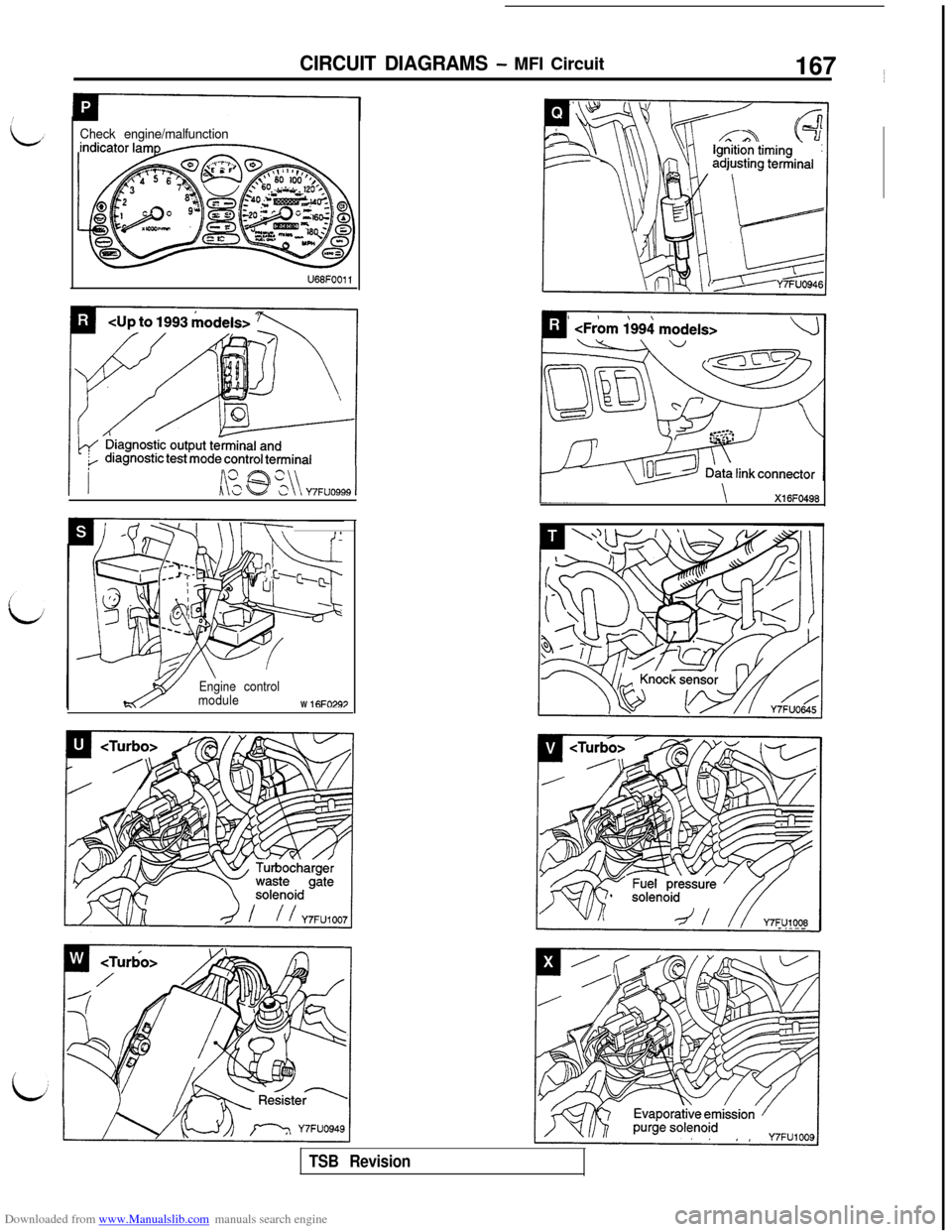
Check engine/malfunction
Lki @ %\\ Y7FUO999 1
\l-T-T-. .
Engine control
moduleW
16FO297
Xl 6FO498
TSB Revision
Page 173 of 738
Downloaded from www.Manualslib.com manuals search engine CIRCUIT DIAGRAMS - MFI Circuit
,’
L
c
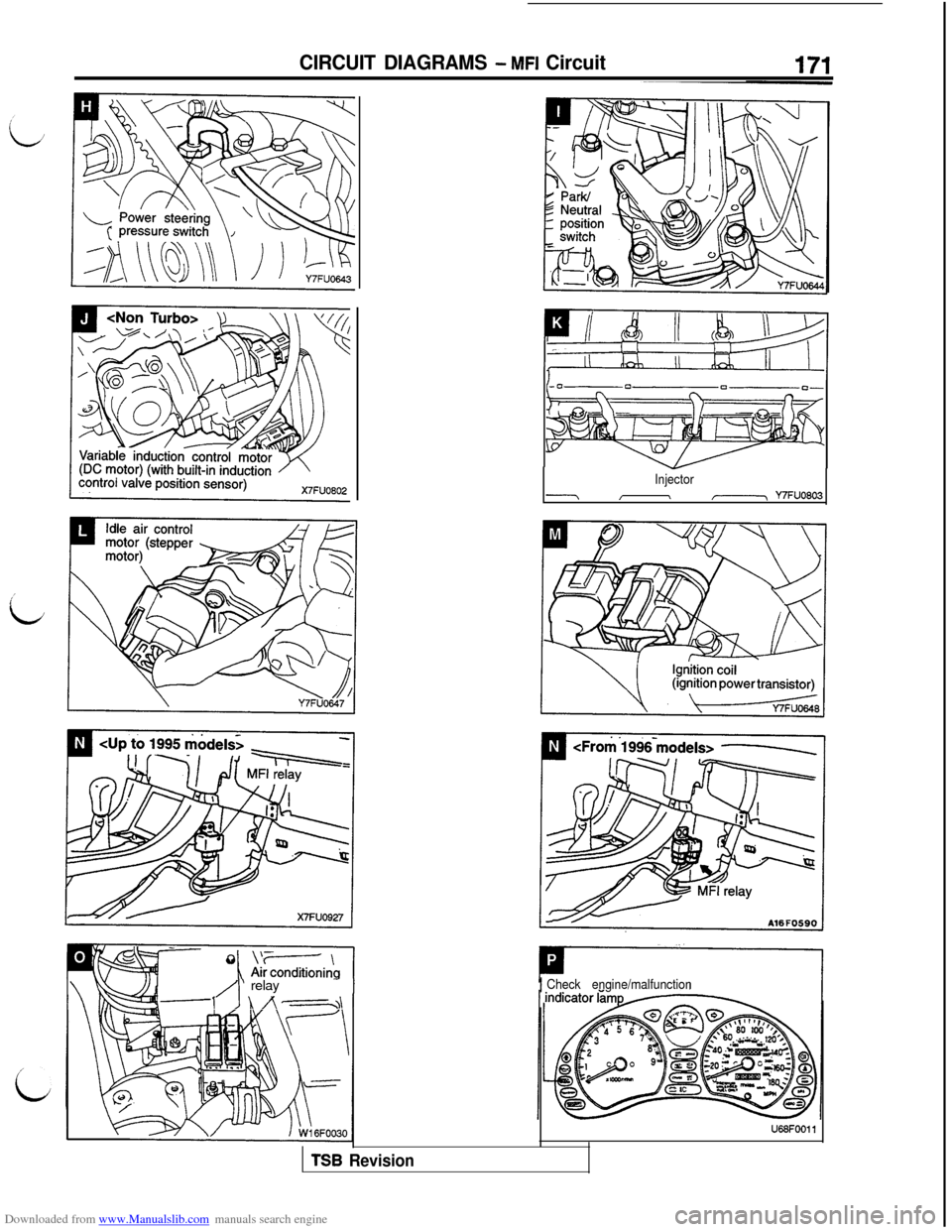
Injector
-I\/-, Y7FUO803
\ R\/1/I‘ relay- 1
I’ I\,?-==,>\ I
1Check engine/malfunction
U68FOOll
TSB Revision
Page 186 of 738
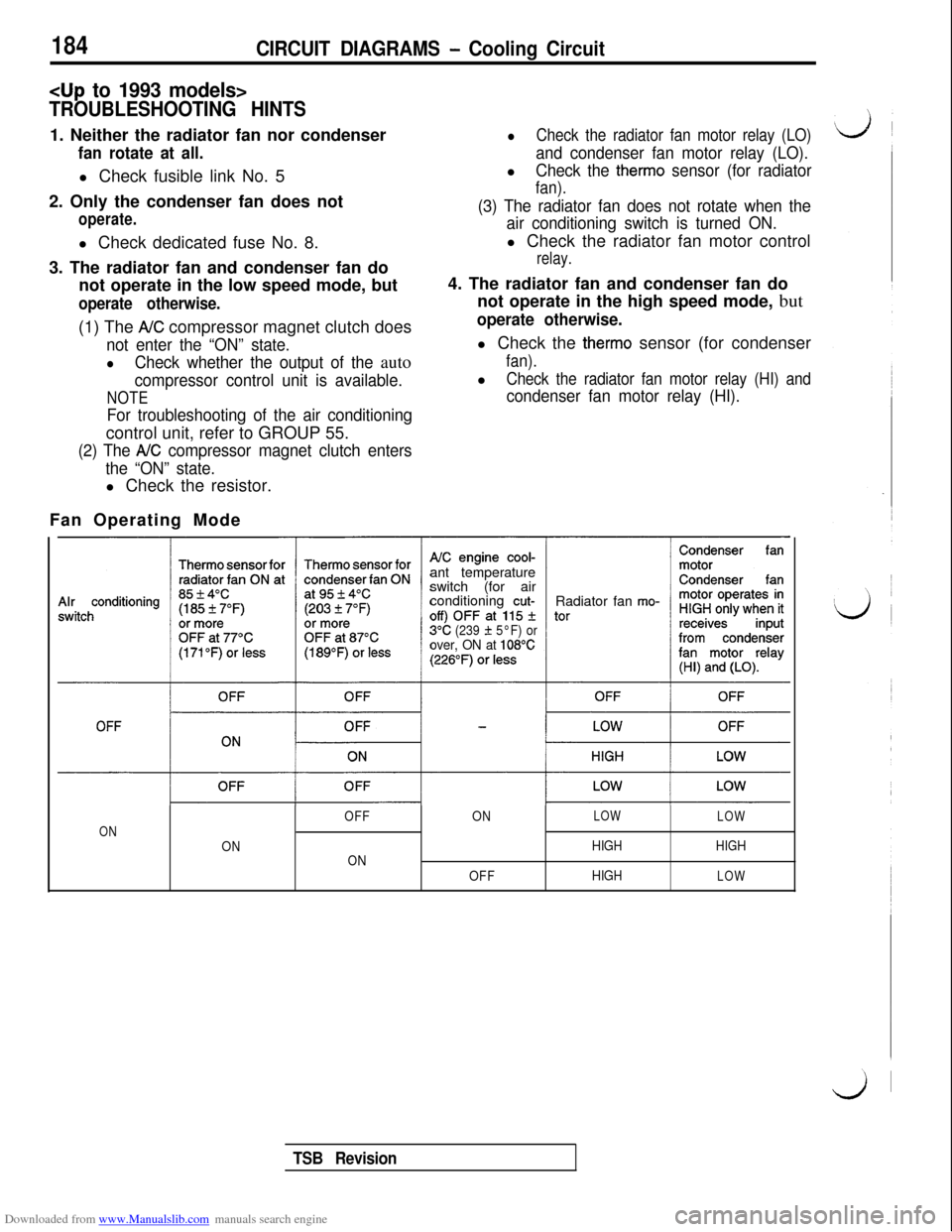
Downloaded from www.Manualslib.com manuals search engine 184CIRCUIT DIAGRAMS - Cooling Circuit
TROUBLESHOOTING HINTS1. Neither the radiator fan nor condenser
fan rotate at all.l Check fusible link No. 5
2. Only the condenser fan does not
operate.l Check dedicated fuse No. 8.
3. The radiator fan and condenser fan do
not operate in the low speed mode, but
operate otherwise.(1) The
AK compressor magnet clutch does
not enter the “ON” state.
lCheck whether the output of the auto
compressor control unit is available.
NOTE
For troubleshooting of the air conditioningcontrol unit, refer to GROUP 55.
(2) The A/C compressor magnet clutch enters
the “ON” state.l Check the resistor.
lCheck the radiator fan motor relay (LO)
and condenser fan motor relay (LO).l
Check the therm0 sensor (for radiator
fan).
(3) The radiator fan does not rotate when the
air conditioning switch is turned ON.l Check the radiator fan motor control
relay.4. The radiator fan and condenser fan do
not operate in the high speed mode, but
operate otherwise.l Check the
therm0 sensor (for condenser
fan).l
Check the radiator fan motor relay (HI) and
condenser fan motor relay (HI).Fan Operating Mode
ant temperature
switch (for air
conditioning
cut-Radiator fan mo-
3°C(239 f 5°F) orover, ON at 108°C
OFFONLOW
LOW
ON
ONHIGHHIGH
ON
OFFHIGH
LOW
TSB Revision
Page 187 of 738
Downloaded from www.Manualslib.com manuals search engine CIRCUIT DIAGRAMS - Cooling Circuit185
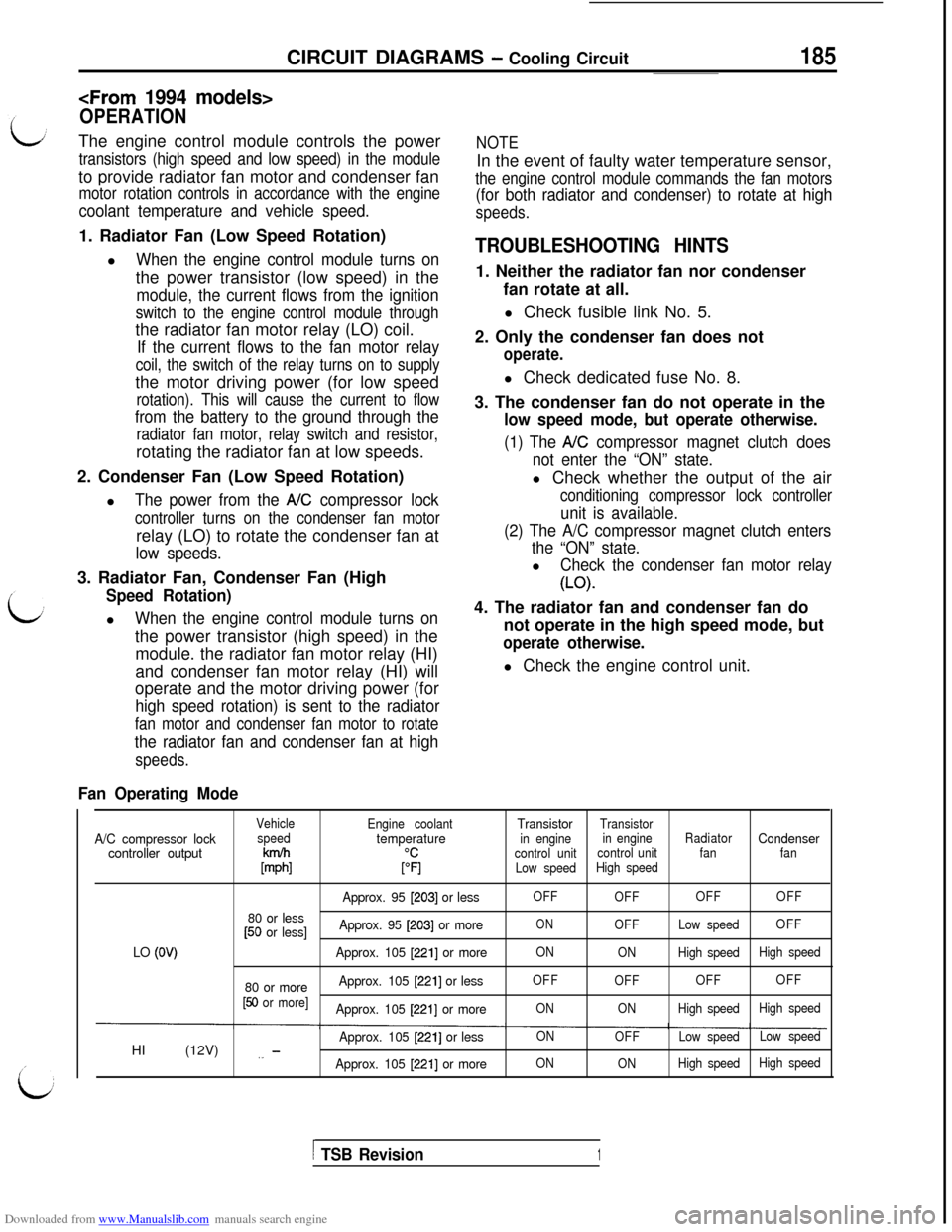
OPERATIONThe engine control module controls the power
transistors (high speed and low speed) in the moduleto provide radiator fan motor and condenser fan
motor rotation controls in accordance with the engine
coolant temperature and vehicle speed.
NOTEIn the event of faulty water temperature sensor,
the engine control module commands the fan motors
(for both radiator and condenser) to rotate at high
speeds.1. Radiator Fan (Low Speed Rotation)
l
When the engine control module turns onthe power transistor (low speed) in the
module, the current flows from the ignition
switch to the engine control module throughthe radiator fan motor relay (LO) coil.
If the current flows to the fan motor relay
coil, the switch of the relay turns on to supplythe motor driving power (for low speed
rotation). This will cause the current to flow
from the battery to the ground through the
radiator fan motor, relay switch and resistor,rotating the radiator fan at low speeds.
2. Condenser Fan (Low Speed Rotation)
l
The power from the NC compressor lock
controller turns on the condenser fan motorrelay (LO) to rotate the condenser fan at
low speeds.3. Radiator Fan, Condenser Fan (High
Speed Rotation)l
When the engine control module turns onthe power transistor (high speed) in the
module. the radiator fan motor relay (HI)
and condenser fan motor relay (HI) will
operate and the motor driving power (for
high speed rotation) is sent to the radiator
fan motor and condenser fan motor to rotate
the radiator fan and condenser fan at high
speeds.
TROUBLESHOOTING HINTS1. Neither the radiator fan nor condenser
fan rotate at all.
l Check fusible link No. 5.
2. Only the condenser fan does not
operate.l Check dedicated fuse No. 8.
3. The condenser fan do not operate in the
low speed mode, but operate otherwise.
(1) The A/C compressor magnet clutch does
not enter the “ON” state.l Check whether the output of the air
conditioning compressor lock controller
unit is available.
(2) The A/C compressor magnet clutch enters
the “ON” state.l
Check the condenser fan motor relay
(LO)-4. The radiator fan and condenser fan do
not operate in the high speed mode, but
operate otherwise.l Check the engine control unit.
Fan Operating Mode
VehicleA/C compressor lockspeedcontroller output
k%
80 or less[50 or less]
LO
(OV)
80 or more[50 or more]HI (12V)
,_ -
Engine coolanttemperature
$1
Approx. 95 [203] or less
Approx. 95
[203] or more
Approx. 105
[221] or more
Approx. 105
[221] or less
Approx. 105
[221] or more
Approx. 105
[221] or less
Approx. 105
12211 or moreTransistor
Transistor
in enginein engineRadiatorCondensercontrol unitcontrol unitfanfan
Low speedHigh speed
OFF
OFFOFFOFF
ONOFFLow speedOFF
ON
ONHigh speedHigh speed
OFF
OFFOFFOFF
ONONHigh speedHigh speed
ON
OFFLow speedLow speed
ON
ONHigh speedHigh speed
1 TSB Revision1