heater MITSUBISHI 3000GT 1992 2.G User Guide
[x] Cancel search | Manufacturer: MITSUBISHI, Model Year: 1992, Model line: 3000GT, Model: MITSUBISHI 3000GT 1992 2.GPages: 738, PDF Size: 35.06 MB
Page 411 of 738
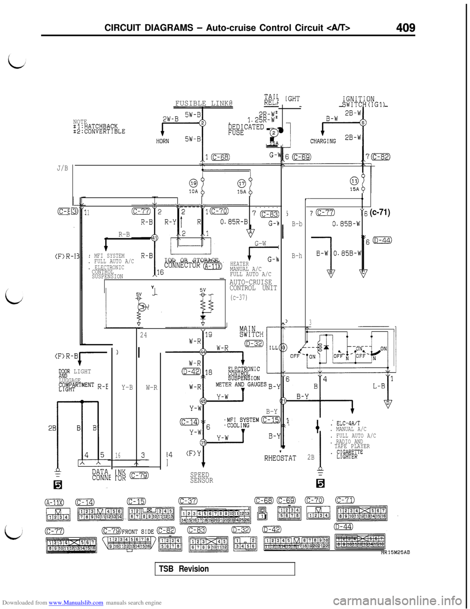
Downloaded from www.Manualslib.com manuals search engine CIRCUIT DIAGRAMS - Auto-cruise Control Circuit
2R-W'1.25R-W'
B&~k""'""r0
15A
NOTE:l:HATCHBACK:2:CONVERTIBLE
J/B
(C-E
015A0
,
7m“6 (c-71)
0.85B-W
@010A15A
vV------
1170
G-b
R-B
r-
(F)R-I
5
B-b
B-h
1
G-W
cG-hHEATERMANUAL A/C
FULL AUTO A/C
AUTO-CRUISE
CONTROL UNIT
(c-37)
. MFI SYSTEM
. FULL AUTO A/CIOD OR STORAGE. ELECTRONICCONTROL
SUSPENSIONY
3/24
W-R
(F)R-Bi-
Y-B
16
1:;" LIGHT
LUGGAGEfyt&"RTMENT R-E
B-Y
1
+
. ELC-4A/T. MANUAL A/C
. FULL AUTO A/C
. RADIO AND
TAPE PLAYER
2B. fW&;TERHEOkTAT
SPEED
SENSOR
TSB Revision
Page 415 of 738
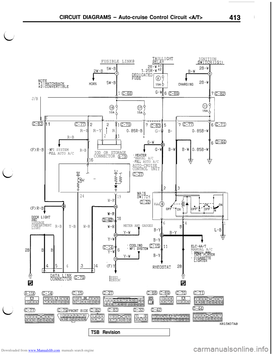
Downloaded from www.Manualslib.com manuals search engine CIRCUIT DIAGRAMS - Auto-cruise Control Circuit
IGNITIONSWITCH(IG1)
J/B
(F>R
rII vu/
i3 11(c-77)“2----“1 (c-70)------
R-B R-Y
r' R
705
0.85R-BG-W B-
R-B2,,lA
41,\
-B.MFI SYSTEMR-B.FULL AUTO A/CIOD OR STORAGECONNECTOR IA-11X).HEATER
,,l6'MANUAL A/C.FULL AUTO A/C
1AUTO-CRUISE
CONTROL UNIT5v
I+ P
-I(c-37)
L
(F)R-Bi-'
;JlXR LI'GHT
LUGGAGE
COMPARTMENT
LIGHT-R-BY-B
6
24
W-R
Y19k%!CH rW-R1m44
-7
W-R
(D-42) la1 1,\/\/
"6"4“1METER AND GAUGES
ELC-4A/TMANUAL A/C. RADIO AND
SPEED
SENSOR
TSB Revision
Page 432 of 738
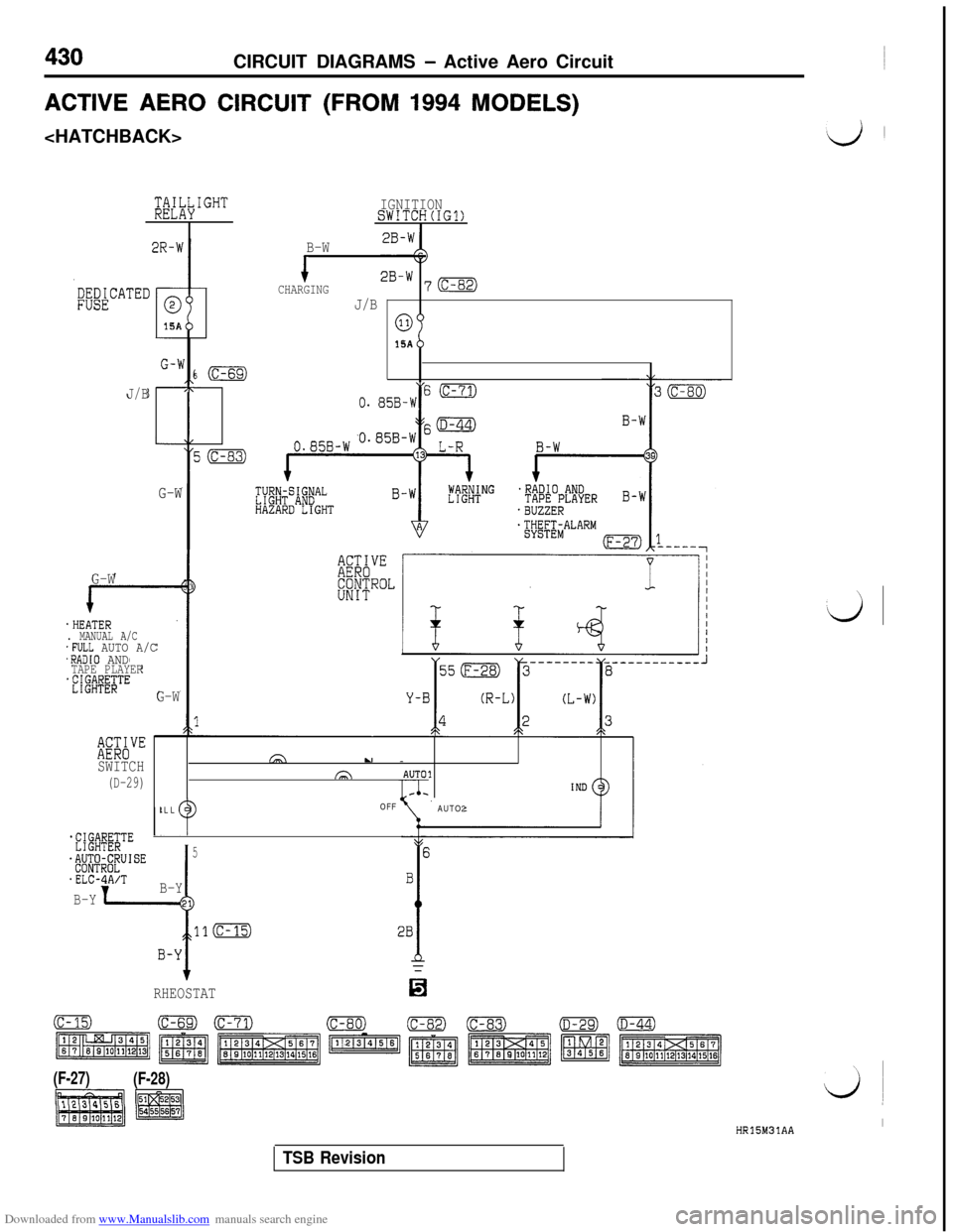
Downloaded from www.Manualslib.com manuals search engine 430CIRCUIT DIAGRAMS - Active Aero Circuit
ACTIVE AERO CIRCUIT (FROM 1994 MODELS)
a;i&IGHTa;i&IGHT
I2R-W
G-W G-W
.HEATER. MANUAL A/C . MANUAL A/C.FULL AUTO A/C.FULL AUTO A/C.RADIO AND.RADIO ANDTAPE PLAYER
WATEDOH15A
G-W6 (c-69)
J/B,\
G-W33
G-W
BKbVESWITCH
(D-29)GA
u -fa
AUTO1.
ILLOFF
AUTO2
*f{@E;TE
d$JJf#JISE
.ELC-A/T
B-YI
5
B-Y
RHEOSTAT
(F-27)
(F-28)
HR15M31AAI
IGNITIONSWITCH(IG1)
B-W
1CHARGING2B-W 7(c-82)
J/B
OH15A
0. 85B-!i6 (C-71)
TSB Revision
Page 454 of 738
Downloaded from www.Manualslib.com manuals search engine 16-8ENGINE ELECTRICAL - Charging System
This test determines whether the generator outputs
normal current.(1) Before the test, always be sure to check the
following.l Generator installation
l
Battery (Refer to GROUP 54 - Battery.)
NOTE
The battery to be used should be slightly dis-charged. The load in a fully-charged battery
will be insufficient and the test may not be able
to be carried out correctly.l Generator drive belt tension (Refer to
GROUP 11- On-vehicle Service.)l Fusible link
l Abnormal noise from the generator while
the engine is running(2) Turn the ignition switch to the OFF position.
(3) Disconnect the negative battery cable.
(4) Disconnect the generator output wire from the
generator
“B” terminal and connect a DC testammeter with a range of O-100 A in series
between the “B” terminal and the disconnected
output wire. (Connect the
(+) lead of the amme-ter to the
“B” terminal, and then connect the(-) lead of the ammeter to the disconnected
output wire.)
Caution
Never use clips but tighten bolts and nutsto connect the line.
Otherwise loose
connections (e.g. using clips) will lead to
a serious accident because of high current.
NOTE
A clamp-type ammeter which enables measure-
ments to be taken without disconnecting the
generator output wire is recommended.(5) Connect a voltmeter with a range of 0
- 20
V between the generator “B” terminal and the
ground. (Connect the
(+) lead of the voltmeterto the “B” terminal, and then connect the (-)
lead of the voltmeter to the ground.)
(6) Connect a tachometer. (For the procedure forconnecting the tachometer, refer to GROUP
11 - On-vehicle Service.)
(7) Connect the negative battery cable.
(8) Leave the hood open.(9) Check to be sure that the reading on the
voltmeter is equal to the battery voltage.
NOTE
If the voltage is 0 V, the cause is probably an
open circuit in the wire or fusible link between
the generator “B” terminal and the battery
(+)
terminal.
(1O)After turning the light switch on and turning on
the headlights, start the engine.
(1l)lmmediately after setting the headlights to high
beam and turning the heater blower switch to
the high revolution position, increase the enginespeed to 2,500
r/min and read the maximum
current output value displayed on the ammeter.
Limit value: 70% of nominal current output
NOTEl
For the nominal current output, refer to the
Generator Specifications.l
Because the current from the battery will
soon drop after the engine is started, the
above step should be carried out as quickly
as possible in order to obtain the maximum
current output value.l The current output value will depend on
the electrical load and the temperature of
the generator body.l
If the electrical load is small while testing,the specified level of current may not be
output even though the generator is normal.
In such cases, increase the electrical load
by leaving the headlights turned on for sometime to discharge the battery or by using
the lighting system in another vehicle, and
then test again.l
The specified level of current also may not
be output if the temperature of the generator
body or the ambient temperature is too high.
In such cases, cool the generator and then
test again.
(12)The reading on the ammeter should be above
the limit value. If the reading is below the limit
value and the generator output wire is normal,
remove the generator from the engine and check
the generator.(13)Run the engine at idle speed after the test.
(14)Turn the ignition switch to the OFF position.
(15)Disconnect the negative battery cable.
(16)Disconnect the ammeter, voltmeter and
tachometer.(17)Connect the generator output wire to the
generator “B” terminal.
(18)Connect the negative battery cable.
TSB Revision
Page 497 of 738
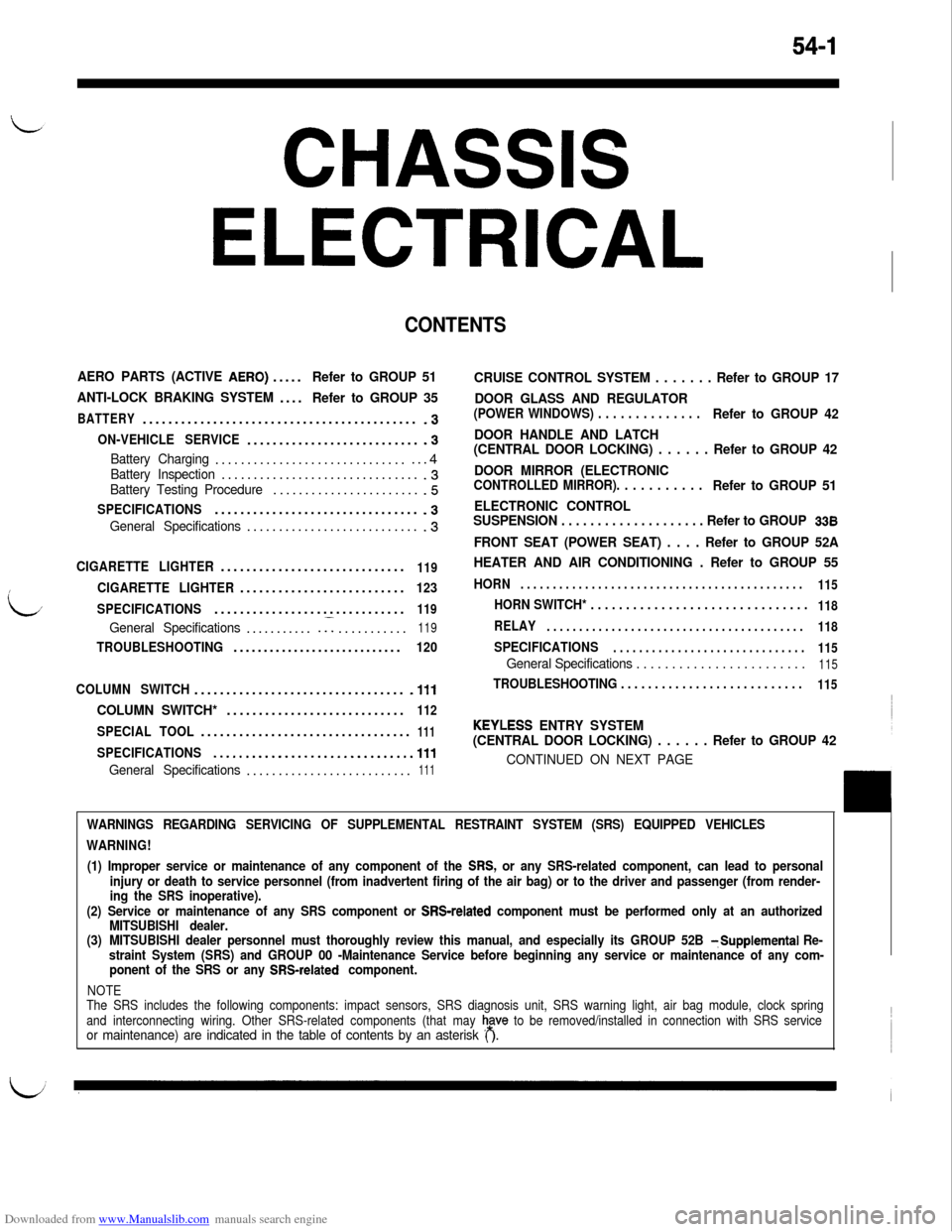
Downloaded from www.Manualslib.com manuals search engine 54-1
CHASSIS
ELECTRICAL
CONTENTS
AERO PARTS (ACTIVE AERO).....Refer to GROUP 51
ANTI-LOCK BRAKING SYSTEM....
Refer to GROUP 35
BATTERY...........................................-3
ON-VEHICLE SERVICE............................3
Battery Charging.................................4Battery Inspection................................3Battery Testing Procedure........................5
SPECIFICATIONS................................-3
General Specifications............................3
CIGARETTE LIGHTER.............................119
CIGARETTE LIGHTER..........................123
SPECIFICATIONS..............................
119
General Specifications............I...........119
TROUBLESHOOTING............................120
COLUMN SWITCH.................................
.lll
COLUMN SWITCH*............................112
SPECIAL TOOL.................................111
SPECIFICATIONS...............................111
General Specifications..........................111
CRUISE CONTROL SYSTEM . . . . . . . Refer to GROUP 17
DOOR GLASS AND REGULATOR
(POWER WINDOWS) . . . . . . . . . . . . . .Refer to GROUP 42
DOOR HANDLE AND LATCH
(CENTRAL DOOR LOCKING) . . . . . . Refer to GROUP 42
DOOR MIRROR (ELECTRONIC
CONTROLLED MIRROR). . . . . . . . . . .Refer to GROUP 51
ELECTRONIC CONTROL
SUSPENSION . . . . . . . . . . . . . . . . . . . . Refer to GROUP
338
FRONT SEAT (POWER SEAT) . . . . Refer to GROUP 52A
HEATER AND AIR CONDITIONING . Refer to GROUP 55
HORN. . . . . . . . . . . . . . . . . . . . . . . . . . . . . . . . . . . . . . . . . . . .
115
HORN SWITCH* . . . . . . . . . . . . . . . . . . . . . . . . . . . . . . .118
RELAY. . . . . . . . . . . . . . . . . . . . . . . . . . . . . . . . . . . . . . . .
118
SPECIFICATIONS. . . . . . . . . . . . . . . . . . . . . . . . . . . . . .
115
General Specifications . . . . . . . . . . . . . . . . . . . . . . . .115
TROUBLESHOOTING . . . . . . . . . . . . . . . . . . . . . . . . . . .115
KEYLESS ENTRY SYSTEM
(CENTRAL DOOR LOCKING) . . . . . . Refer to GROUP 42
CONTINUED ON NEXT PAGE
WARNINGS REGARDING SERVICING OF SUPPLEMENTAL RESTRAINT SYSTEM (SRS) EQUIPPED VEHICLES
WARNING!
(1) Improper service or maintenance of any component of the
SRS, or any SRS-related component, can lead to personal
injury or death to service personnel (from inadvertent firing of the air bag) or to the driver and passenger (from render-
ing the SRS inoperative).
(2) Service or maintenance of any SRS component or
SRS-related component must be performed only at an authorized
MITSUBISHI dealer.
(3)MITSUBISHI dealer personnel must thoroughly review this manual, and especially its GROUP 52B
TSupplemental Re-
straint System (SRS) and GROUP 00 -Maintenance Service before beginning any service or maintenance of any com-
ponent of the SRS or any
SRS-related component.
NOTE
The SRS includes the following components: impact sensors, SRS diagnosis unit, SRS warning light, air bag module, clock spring
and interconnecting wiring. Other SRS-related components (that may
h,a”” to be removed/installed in connection with SRS serviceor maintenance) are indicated in the table of contents by an asterisk ( ).
Page 612 of 738
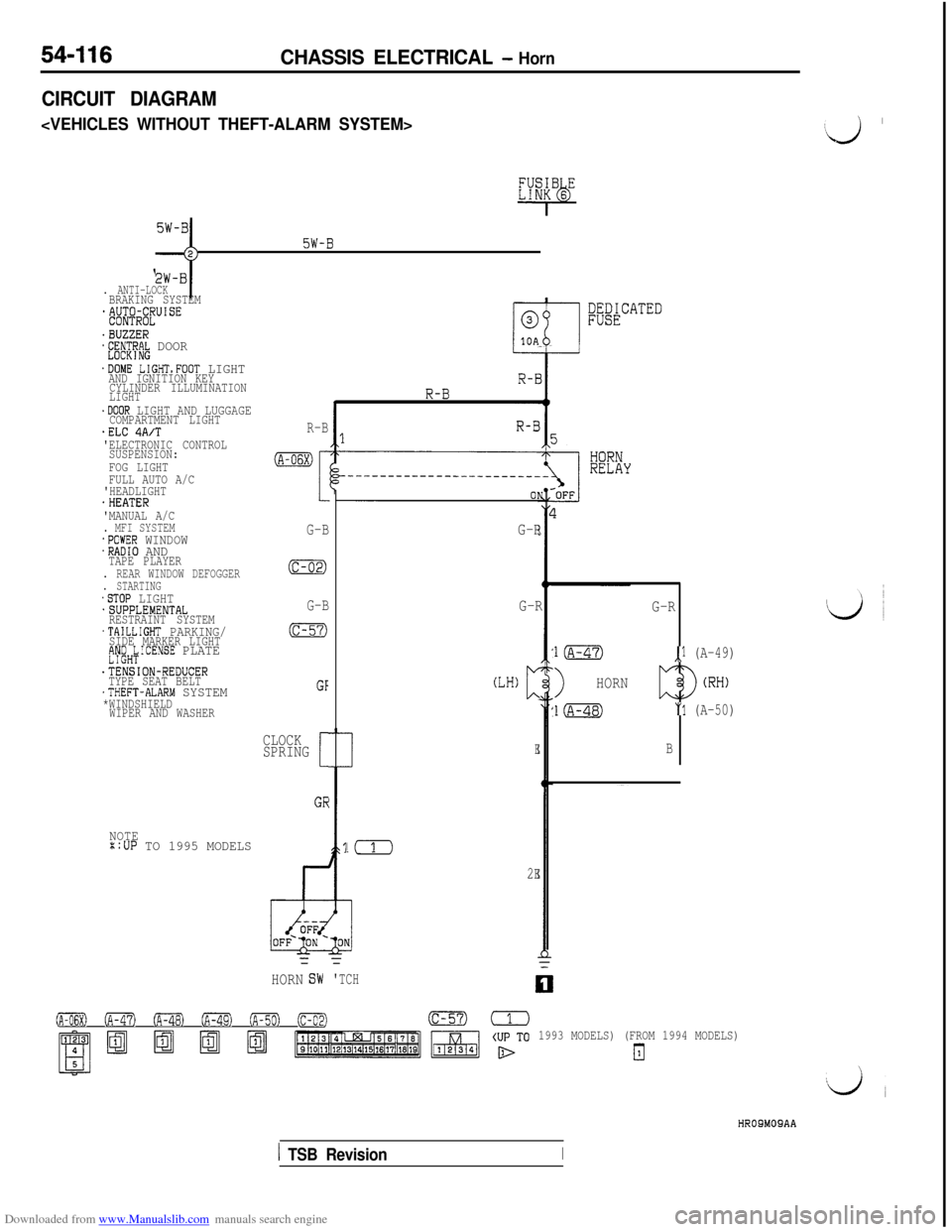
Downloaded from www.Manualslib.com manuals search engine 54-116CHASSIS ELECTRICAL - Horn
CIRCUIT DIAGRAM
c
5W-B;;-j
. ANTI-LOCKBRAKING SYSTEM*&$@lJUISE
.BUZZER*E;~CT~R~ DOOR
.DOME LIGHTsFOOT LIGHTAND IGNITION KEY
CYLINDER ILLUMINATION
LIGHT
.DOOR LIGHT AND LUGGAGECOMPARTMENT LIGHT.ELC 4A/T'ELECTRONIC CONTROL
SUSPENSION:
FOG LIGHT
FULL AUTO A/C
'HEADLIGHT
.HEATER
'MANUAL A/C
. MFI SYSTEM.POWER WINDOW.RADIO ANDTAPE PLAYER. REAR WINDOW DEFOGGER. STARTING.STOP LIGHT.SUPPLEMENTAL
RESTRAINT SYSTEM
.TAILLIGHT PARKING/SIDE MARKER LIGHTfJy;H;ICENSE PLATE
.TENSION-REDUCER
TYPE SEAT BELT
.THEFT-ALARM SYSTEM*WINDSHIELD
WIPER AND WASHER
NOTE::UP TO 1995 MODELS
R-B
(A-06X)
I
G-B
(c-02)
G-B
(c-57)
GF
CLOCK
SPRING
[
GE
;;&CATED
G-R
!(
2E=
HORNG-R
(LH)c
E
=
'TCH
G-R
l(A-47),l (A-49)
>HORN
l(A-48)"1 (A-50)
B
0 (A-47) oFa (A-49) ofiml (c-02)(c-57)=
1993 MODELS) (FROM 1994 MODELS)
El
‘J ’
HROSMOSAA
1 TSB RevisionI
Page 617 of 738
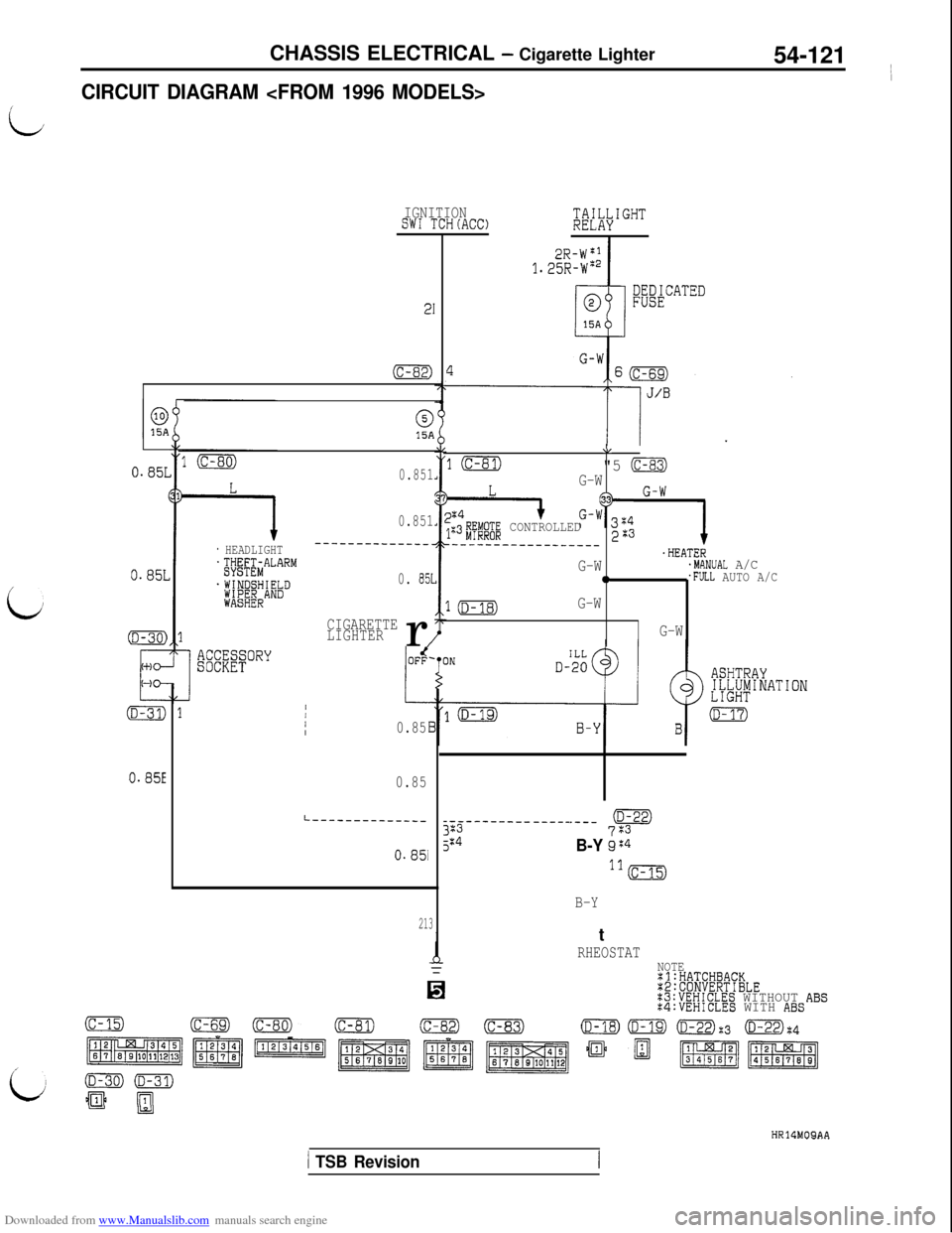
Downloaded from www.Manualslib.com manuals search engine CHASSIS ELECTRICAL - Cigarette Lighter
54-121 ~
I
CIRCUIT DIAGRAM
L
IGNITIONSW1 TCH(AC0;&I""'
I
;&$CATED
21
(c-82)
015A
0.851
0.851
_______--____-_
0. 851
CIGARETTE
LIGHTERr
/
\I
10"5 (c-83)G-W
I+G-?3z4 G-W;:3#E;"@ CONTROLLED223--__--___----______.HEATERG-W.MANUAL A/C0.FULL AUTO A/C
1mG-W
G-W
0.85L
/
0.85L
* HEADLIGHT~~~~;&A""""
.WINDSHIELD;ft;;ERAND
L
1/III0.85
0.85
.---pt+
B-Y gG4ll(c-15)
B-Y
L------------------------- -----3235:40.85i
213IRHEOSTATNOTE:l:HATCHBACK:2:CONVERTIBLE:3:VEHICLES WITHOUT ABS:4:VEHICLES WITH ABS
(c-15)(c-82)(D-22):3 (D-22):4
p$$g'Tqgq,
ii
HR14MOQAA
1 TSB Revision
Page 639 of 738
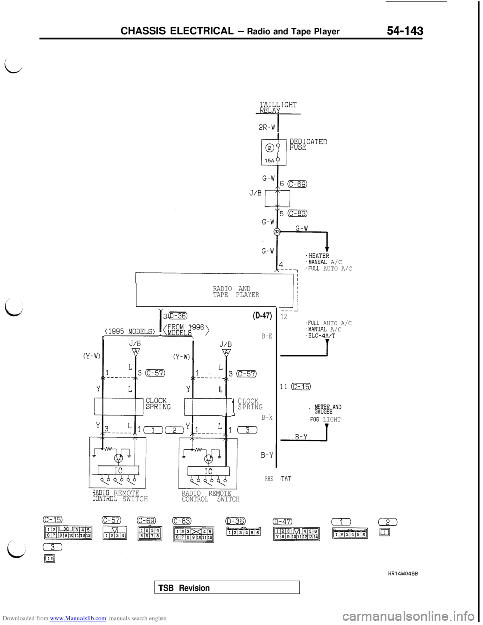
Downloaded from www.Manualslib.com manuals search engine CHASSIS ELECTRICAL - Radio and Tape Player54-143
i@;X&GHT
-i-q-
.HEATER.MANUAL A/C.FULL AUTO A/C
RADIO AND
TAPE PLAYER
L1
------.
Y
t
L
. .i
t
(D-47)
B-E
1
CLOCK
SPRING
_IB-k
0
?ADIO REMOTE:ONTROL SWITCHRADIO REMOTE
CONTROL SWITCH
0-Y
RHE
3
---212.FULL AUTO A/C.MANUAL A/C.ELC-4A/T
1
.1 (c-15)
. ,$&AND
.FOG LIGHT
'TAT
HR14M04BB
TSB Revision
Page 642 of 738
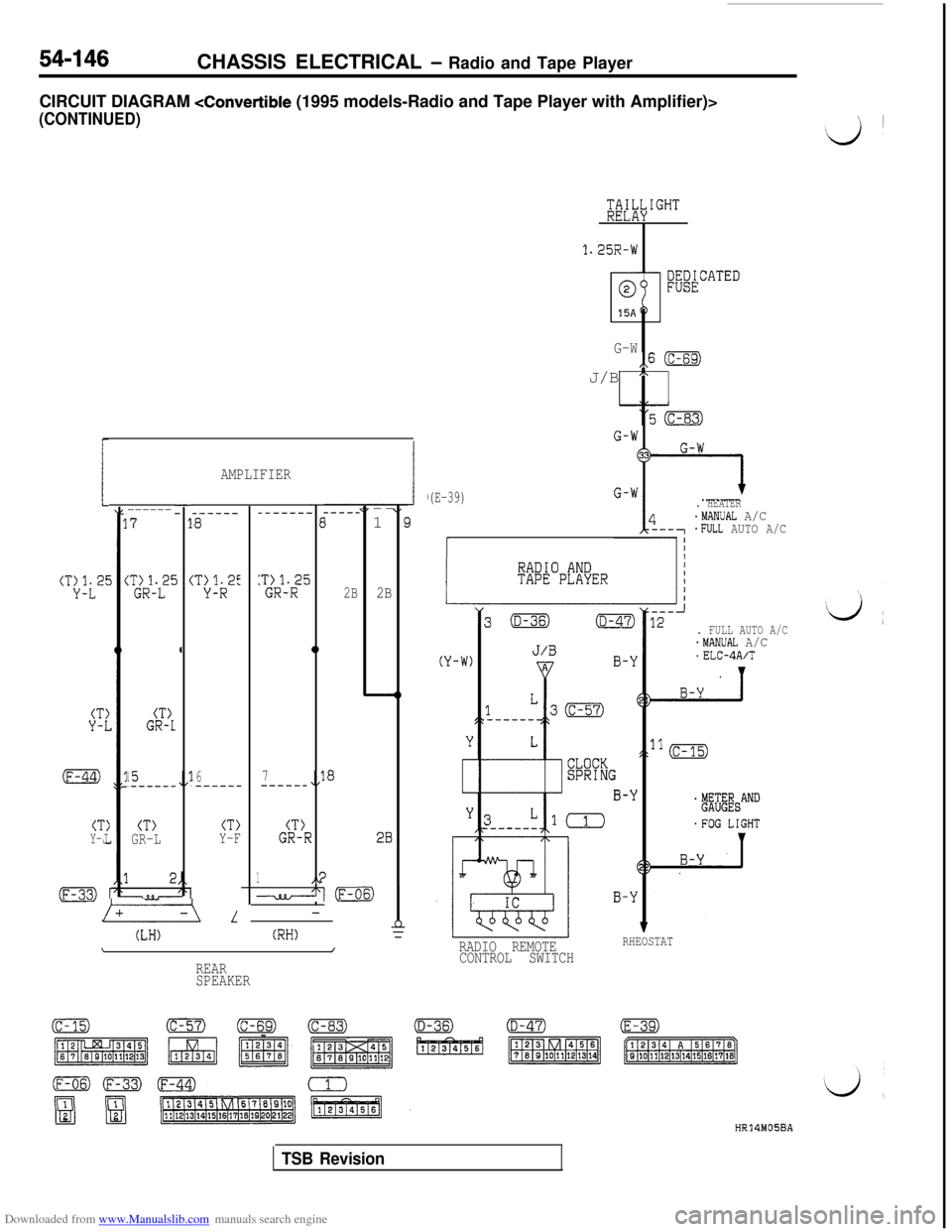
Downloaded from www.Manualslib.com manuals search engine 54-146CHASSIS ELECTRICAL - Radio and Tape Player
CIRCUIT DIAGRAM
(CONTINUED)
tT:i2E
--------71
i (%-i?
4
:*tL2'
CT)GR-1
15.------,/l6--__--
CT)Y-JCT)GR-L
L
(LH)
AMPLIFIER
_-----a
CT>Y-F
-_------E
5:T~R12-t
0
2B
a7---___,,l
(T)GR-r.?
1I‘4d(F-(-
(RH)\/
REAR
SPEAKER---
1
E
2B
28
/
1.25R-W
G-W,,6 (c-69)J/B
n
(E-39). HEATER.MANUAL A/C*FULL AUTO A/C
I
. FULL AUTO A/C.MANUAL A/C.ELC-4A/T
RADIO REMOTERHEOSTAT
CONTROL SWITCH
HR14M05BA
TSB Revision
Page 645 of 738
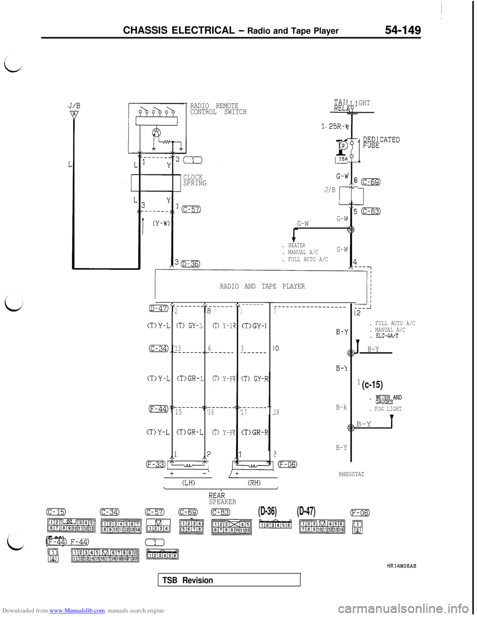
Downloaded from www.Manualslib.com manuals search engine CHASSIS ELECTRICAL - Radio and Tape Player
RADIO REMOTE
CONTROL SWITCHKK1
1.25R-kr
@
GHT
1
;@ATED
i
I6CLOCKSPRINGJ/B
r
. FULL AUTO A/C
G-WG-W
. HEATER. MANUAL A/CG-W
. FULL AUTO A/C
. MANUAL A/C
. ELC-4A/T
1B-Y RADIO AND TAPE PLAYER
i
I-----_OV -“,----_-v------281
(T)Y-LCT) GY-:LCT> Y-li(T>GY-I
_---_----___--____7
(c-34),: .,~1363_-----_------__------
(T>Y-L(T>GR-LCT> Y-F(T> GY-I
_----__------.(F-44)>? q'-.------15161718B-k
(T>Y-L 2(T)GR-ICT> Y-F(T>GR-F
B-Y1
-m
1:2/\
mz7LL/-I:
+-/+
(LH)(RH)\/
RHEOSTAT
,l (c-15)
. b&&&AND
. FOG LIGHTB-Y
1
REAR
SPEAKER
(c-15)(c-34)(c-57)00(D-36)(D-47)(F-06)
c ~~~~1~1~~~
(F-33)Fm)
mB(iisiEa
HR14MOGAB
TSB Revision