heater MITSUBISHI 3000GT 1992 2.G Owner's Manual
[x] Cancel search | Manufacturer: MITSUBISHI, Model Year: 1992, Model line: 3000GT, Model: MITSUBISHI 3000GT 1992 2.GPages: 738, PDF Size: 35.06 MB
Page 650 of 738
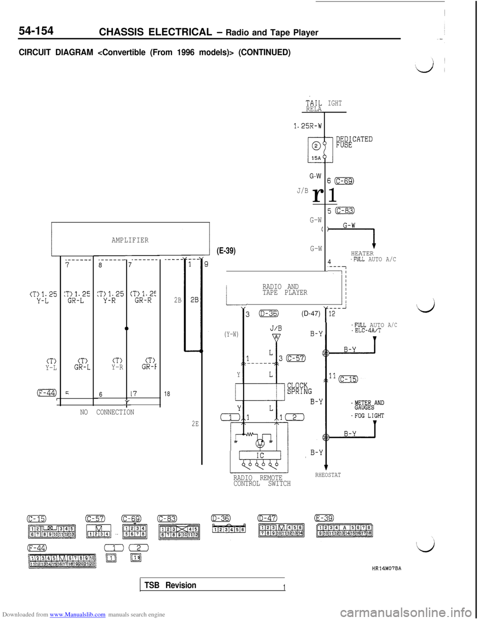
Downloaded from www.Manualslib.com manuals search engine 54-154CHASSIS ELECTRICAL - Radio and Tape Player
CIRCUIT DIAGRAM
(T:Jt25
--7
i
0
CT>CT>CT>CT>Y-LGR-LY-RGR-F
F61718"-
AMPLIFIER
.------8_-----_----L
2B
NO CONNECTION
2E
(E-39)G-W
TiIL
RELA
1.25R-W
G-W
J/Br
G-W
(
-L
(Y-W)
Y
i
r
rr
RADIO AND_ 11TAPE PLAYER
---3(D-36)(D-47)r12 i
IGHT
S(c-69)
1
7HEATER
4'FULL AUTO A/C
'---7-1
*FULL AUTO.ELC-4A/T
RADIO REMOTERHEOSTAT
CONTROL SWITCH
A/C
HR14M07BA
TSB Revision1
Page 689 of 738
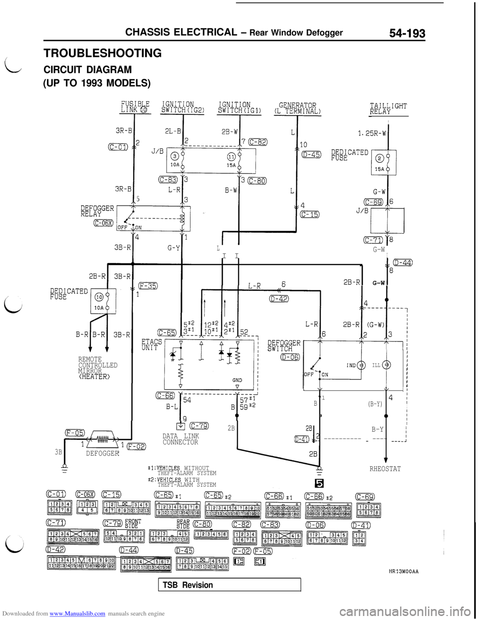
Downloaded from www.Manualslib.com manuals search engine CHASSIS ELECTRICAL - Rear Window Defogger54-193
8,TROUBLESHOOTINGCIRCUIT DIAGRAM
(UP TO 1993 MODELS)
3R-B
5
;&iL#GHT
I
LI IG-WI
- t
8=
i nF;2B-RG-W
REMOTE
CONTROLLED
MIRROR
(HEATER>
3B
DEFOGGER
nZ
+j m
DATA LINK
CONNECTOR
:l:VEHICLES WITHOUTTHEFT-ALARM SYSTEMX2:VEHICLES WITHTHEFT-ALARM SYSTEM
(c-65):1(c-65)
ILL
J I1 \L\I II“1I
B(B-Y)4 IIII0II
2BIB-Y
(i&y,2 ---------- - ---- ----1
f
RHEOSTAT
HR13MOOAA
TSB Revision
Page 696 of 738
Downloaded from www.Manualslib.com manuals search engine 54-200CHASSIS ELECTRICAL - Rear Window Defogger
OPERATIONl
If the defogger switch is turned to “ON” when the generator is generating electricity (L terminal exceeds
10 V.) with the ignition switch at the “ON” position, the timer circuit in the ETACS unit will be operated
to keep the transistor “on” for 11 minutes to close the contact point of the defogger relay. When the
defogger relay is “on”,the defogger and mirror heater will be activated. Moreover, the indicator lightof the defogger switch is lit to inform that the defogger and mirror heater are activated.
lWhen 11 minutes have passed, the defogger and mirror heater will stop activating even if the defoggerswitch is at “ON”. When the defogger and mirror heater are activated (the timer is activated), they
will also stop activating even if the defogger switch is set at “ON” again or if the generator stops
generating electricity (the terminal is 3.5 V or less.)
NOTE
The light automatic shut-off system is valid for the illumination light of the defogger switch. (Refer to
P.54-37.)
TROUBLESHOOTING HINTS
NOTE
For the troubleshooting hints of the automatic light shut-OFF system, refer to P.54-38.
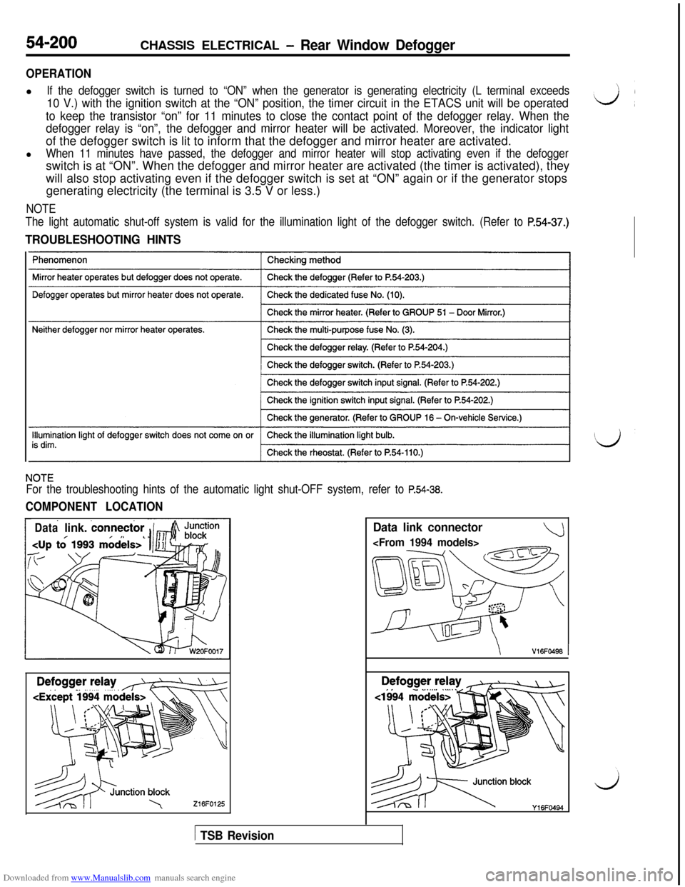
COMPONENT LOCATION
Datalink. connector
216FO125
Data link connector
\V16FO496 1
es.-‘) blocky,6Fww
1 TSB Revision
Page 699 of 738
Downloaded from www.Manualslib.com manuals search engine CHASSIS ELECTRICAL - Rear Window Defogger54-203
L
L-J
c
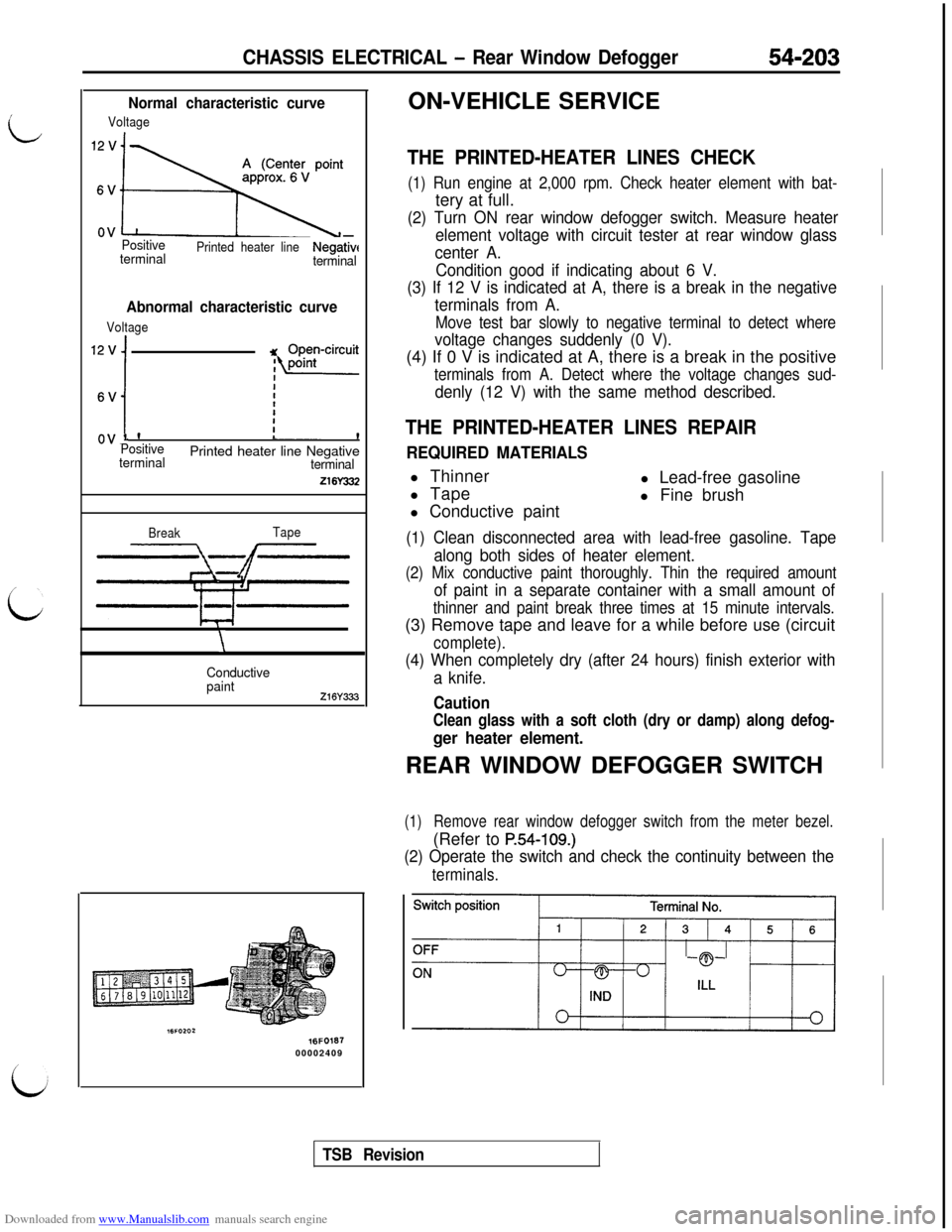
Normal characteristic curve
Voltage
j\
PositivePrinted heater lineterminalNegativeterminal
Abnormal characteristic curve
Voltage
Qj (( r”!“Yui;
Positive
terminalPrinted heater line Negativeterminal
216Y332
BreakTape
\
Conductive
paint
216Y333
16FO16700002409ON-VEHICLE SERVICE
THE PRINTED-HEATER LINES CHECK
(1) Run engine at 2,000 rpm. Check heater element with bat-tery at full.
(2) Turn ON rear window defogger switch. Measure heater
element voltage with circuit tester at rear window glass
center A.
Condition good if indicating about 6 V.
(3) If 12 V is indicated at A, there is a break in the negative
terminals from A.
Move test bar slowly to negative terminal to detect where
voltage changes suddenly (0 V).(4) If 0 V is indicated at A, there is a break in the positive
terminals from A. Detect where the voltage changes sud-
denly (12 V) with the same method described.
THE PRINTED-HEATER LINES REPAIR
REQUIRED MATERIALSl Thinner
l Tapel Lead-free gasoline
l Fine brush
l Conductive paint
(1) Clean disconnected area with lead-free gasoline. Tape
along both sides of heater element.
(2) Mix conductive paint thoroughly. Thin the required amount
of paint in a separate container with a small amount of
thinner and paint break three times at 15 minute intervals.(3) Remove tape and leave for a while before use (circuit
complete).
(4) When completely dry (after 24 hours) finish exterior with
a knife.
Caution
Clean glass with a soft cloth (dry or damp) along defog-
ger heater element.REAR WINDOW DEFOGGER SWITCH
(1)Remove rear window defogger switch from the meter bezel.(Refer to
P.54-109.)
(2) Operate the switch and check the continuity between the
terminals.
TSB Revision
Page 733 of 738
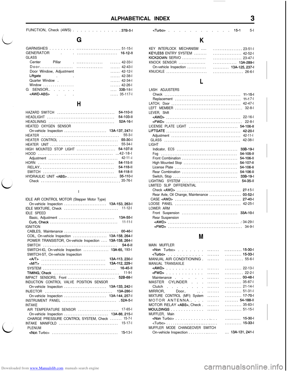
Downloaded from www.Manualslib.com manuals search engine ALPHABETICAL INDEX3FUNCTION, Check (4WS) .
. . . . . . . . . . . .37B-5-l
GARNISHES . . . . . . . . .
GENERATOR . .
GLASSCenter Pillar .
Door.....................
Door Window, Adjustment
Liftgate . .Quarter Window.Window. . . . . . . . . . . . . . . .G SENSOR.. . . . . .
G
.........................51-15-l........................16-12-11
.....................42-33-l.....................42-43-l......42-12-l......42-38-l......42-34-l......42-26-l....338-l 8-l.....35-117-l
H
HAZARD SWITCH..................................54-110-11
HEADLIGHT........................................54-103-11
HEADLINING.......................................52A-16-l
HEATED OXYGEN SENSOROn-vehicle Inspection.........................13A-137,247-l
HEATER..............................................55-3-l
HEATER CONTROL...................................55-30-I
HEATER UNIT........................................55-34-l
HIGH MOUNTED STOP LIGHT.......................54-107-11
HOOD...............................................42-18-lAdjustment.........................................42-11 -I
HORN.............................................54-115-11RELAY..
..........................................54-118-11
SWITCH..........................................54-118-11
HYDRAULIC UNIT CABS>.............................35-110-I
Check
.............................................35-76-lI
IDLE AIR CONTROL MOTOR (Stepper Motor Type)
On-vehicle Inspection.........................13A-153,263-l
IDLE MIXTURE, Check................................11-12-l
IDLE SPEED
Basic, Adjustment.................................13A-55-lCurb,Check........................................11-11-l
IGNITION
CABLES, Maintenance................................00-46-l
COIL, On-vehicle Inspection....................
13A-158,264-l
POWER TRANSISTOR, On-vehicle Inspection....13&158,264-l
SWITCH............................................54-6-11
SWITCH-IG, On-vehicle Inspection...............13A-65, 193-l
SWITCH-ST, On-vehicle Inspection
......................................13A-113,230-l
SYSTEM...........................................16-45-11
TIMING,‘Check.......................................11-9-l
IMPACT SENSORS, Front............................528-68-I
INDUCTION CONTROL VALVE POSITION SENSOROn-vehicle Inspection.........................13A-133,242-l
INJECTOR........................................13A-286-l
On-vehicle Inspection.........................
13A-144,257-l
INSTRUMENT PANEL.................................52A-5-lINTAKE
AIR TEMPERATURE SENSOR........................17-65-l
On-vehicle Inspection..........................13A-88,215-l
CHARGE PRESSURE CONTROL SYSTEM, Check.......15-7-l
INTAKE MANIFOLD...................................15-17-l
PLENUM
K
KEY INTERLOCK MECHANISM....KEYLESS ENTRY SYSTEM........KICKDOWN SERVO...............KNOCK SENSOR.................On-vehicle Inspection............KNUCKLE........................
.................23-51-l.................42-52-l.................23-47-l..............13A-289-l..........
13A-125,237-l..................26-6-l
L
LASH ADJUSTERSCheck.............................................11-15-lReplacement.......................................11-l 7-l
LATCH, Door.........................................42-47-lLEFT MEMBER........................................32-8-l
LEVER, Shift
cFWD>.............................................22-8-lLICENSE PLATE LIGHT.............................54-106-11
LIFTGATE............................................42-20-I
Adjustment.........................................42-11-l
GLASS.............................................42-38-lLIGHT
Indicator, ECS....................................338-19-IFog.............................................54-105-11Front Combination.................................54-106-11High Mounted Stop................................54-107-11License Plate.....................................54-106-11
Rear Combination.................................54-106-11Switch, Stop......................................33B-19-l
LIGHTING SYSTEM..................................54-35-11LIMITED SLIP DIFFERENTIALCheck cAWD>......................................27-l 5-l
Rear Axle, Oil Change, Maintenance...................00-52-I
CASE
LOOSE PANEL.......................................42-25-l
LOWER ARM
Front Suspension.................................33A-10-I
Rear Suspension
M
MAIN MUFFLER
MANUAL AIR CONDITIONING .
MANUAL TRANSAXLE
cFWD> . . . . . . . . . . . .Maintenance. . . . .
MASTER CYLINDER . . .
Clutch . . . . . . . .
MIRROR, Door..
_. .MIXTURE CONTROL (MFI) SystemMOTOR ANTENNA.. . . .
MOTOR RELAY
CABS>, Check .MOULDINGS . . . . . . . . . . . . .MUFFLER, Main
.....................
.......
...............................................................
..........15-30-I..........
15-33-l...........55-6-l..........
22-13-l...........22-2-l..........00-48-I..........35-87-l..........21-14-l..........51-31-l..........17-70-I........54-188-11..........35-83-l..........51-15-l...........
15-30-I..........15-33-l...
13A-131,241-l