check engine light MITSUBISHI 3000GT 1992 2.G Owner's Manual
[x] Cancel search | Manufacturer: MITSUBISHI, Model Year: 1992, Model line: 3000GT, Model: MITSUBISHI 3000GT 1992 2.GPages: 738, PDF Size: 35.06 MB
Page 504 of 738
Downloaded from www.Manualslib.com manuals search engine 54-8CHASSIS ELECTRICAL - Ignition Switch
216AO57000002296INSPECTION
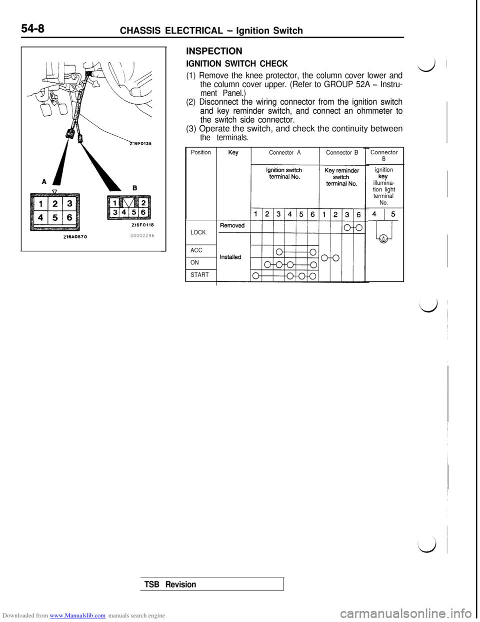
IGNITION SWITCH CHECK
(1) Remove the knee protector, the column cover lower andd’
the column cover upper. (Refer to GROUP 52A - Instru-
ment Panel.)
(2) Disconnect the wiring connector from the ignition switch
and key reminder switch, and connect an ohmmeter to
the switch side connector.(3) Operate the switch, and check the continuity between
the terminals.
PositionKeyConnector AConnector B
LOCK
ACC
ON
START
ConnectorB
ignitionkey
illumina-
tion light
terminal
No.
415
LJ
TSB Revision
Page 514 of 738
Downloaded from www.Manualslib.com manuals search engine 54-18CHASSIS ELECTRICAL - Meters and Gauges
OPERATION
When the ignition key is at the “ON” position,the fuel gauge is activated.
l
When there is much fuel, the unit’s resistanceis small and the current flowing in the circuit
is great, so the gauge’s indicator indicates inthe “F” area.
l When there is little fuel, the unit’s resistance
is high and the current flowing in the circuit
is small, so the gauge’s indicator indicates inthe
“E” area.
lWhen the ignition key is at the “ON” position,
the engine coolant temperature gauge is acti-
vated.l
When the engine coolant temperature is high,
the unit’s resistance is low and there is a greatflow of current in the circuit, so the gauge’s
indicator indicates in the “H” area.
l
When the engine coolant temperature is low,
the unit’s resistance is high and there is a smallflow of current in the circuit, so the gauge’s
indicator indicates in the “C” area.
vehicle speed, and vehicle-speed signals areinput to systems (the MFI system, etc.) that
regulate according to the vehicle speed.
TROUBLESHOOTING HINTS
1.The fuel gauge doesn’t function, or shows the
incorrect indication.
(1) Disconnect the connector of the fuel pumpand gauge unit assembly; the ‘F” side is
indicated when terminal (5) is then
grounded.l Check the fuel gauge.
2.The engine coolant temperature gauge doesn’t
function, or shows the incorrect indication.
(1)The “l-l” side is indicated when the connector
of the engine coolant temperature gauge
unit is disconnected and then grounded.l
Check the engine coolant temperature
gauge unit.
3. Systems dependent upon control according to
the vehicle speed do not function correctly.l Check the reed switch (mechanical
speedometer type)l Check the speed sensor (electrical
speedometer type)
coil pressure gauge>l
When the ignition key is at the “ON” position,
the oil pressure gauge is activated.
lWhen oil pressure is high, the internal contacts
of the gauge unit are kept closed for a longerperiod of time. This causes more current to
flow in the circuit, and the gauge pointer swings
to the high pressure side.
lWhen oil pressure is low, the internal contactsof the gauge unit open in a shorter period of
time. Therefore, there is less current flowing
in the circuit and the gauge pointer swings to
the low pressure side.
lWhen the ignition key is set to the “ON” position,the gauge indicator will be at
“0”.l
When the engine is started, the indicator will
move from
“0” to the minus (-) side, and then,as the boost level increases, it will move to
the plus
(+) side.
position, the voltage gauge operates and indi-
cates a battery voltage of approximately 12 V.l
When the engine is started, the voltage gauge
indicates a battery voltage of 12 to 16 V, indicat-ing that the battery is on charge.
4. The oil pressure gauge doesn’t function, or
shows the incorrect indication.
(1)The “H” side is indicated when the connectorof the oil pressure gauge unit is discon-
nected and then grounded.l Check the oil pressure gauge unit.
5.The meter illumination light does not illuminate.
(1) The tail lights illuminate.l Check the rheostat.
6. The voltage gauge doesn’t function, or shows
the incorrect indication.l Check the voltage gauge.
TSB Revision
Page 523 of 738
Downloaded from www.Manualslib.com manuals search engine I,;CHASSIS ELECTRICAL
- Meters and Gauges54-27
c I\\ zl6F024;
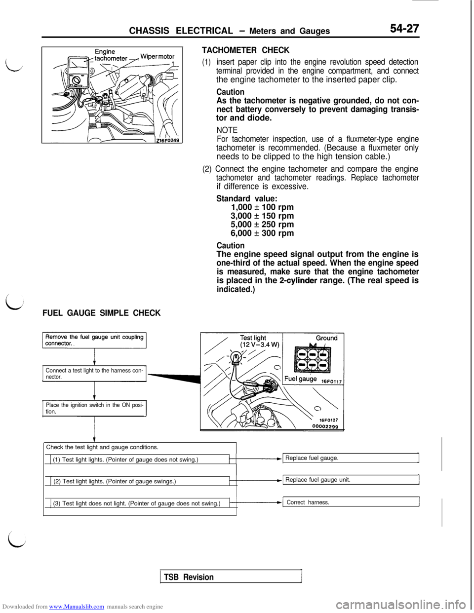
L:FUEL GAUGE SIMPLE CHECKTACHOMETER CHECK
(1)insert paper clip into the engine revolution speed detection
terminal provided in the engine compartment, and connectthe engine tachometer to the inserted paper clip.
Caution
As the tachometer is negative grounded, do not con-
nect battery conversely to prevent damaging transis-tor and diode.
NOTE
For tachometer inspection, use of a fluxmeter-type engine
tachometer is recommended. (Because a fluxmeter onlyneeds to be clipped to the high tension cable.)
(2) Connect the engine tachometer and compare the engine
tachometer and tachometer readings. Replace tachometer
if difference is excessive.
Standard value:1,000
f 100 rpm
3,000
+ 150 rpm
5,000
f 250 rpm
6,000
f 300 rpm
CautionThe engine speed signal output from the engine is
one-third of the actual speed. When the engine speed
is measured, make sure that the engine tachometeris placed in the
2-cylinder range. (The real speed is
indicated.)
Connect a test light to the harness con-nector.
Place the ignition switch in the ON posi-
tion.Check the test light and gauge conditions.
1 (1) Test light lights. (Pointer of gauge does not swing.)/-.-I Replace fuel gauge.
[ (2) Test light lights. (Pointer of gauge swings.)/-.--I Replace fuel gauge unit.1
1 (3) Test light does not light. (Pointer of gauge does not swing.)k-1 Correct harness.I
TSB Revision
Page 524 of 738
Downloaded from www.Manualslib.com manuals search engine 54-28CHASSIS ELECTRICAL - Meters and Gauges
16FO11500002300
16Fo255 00002383
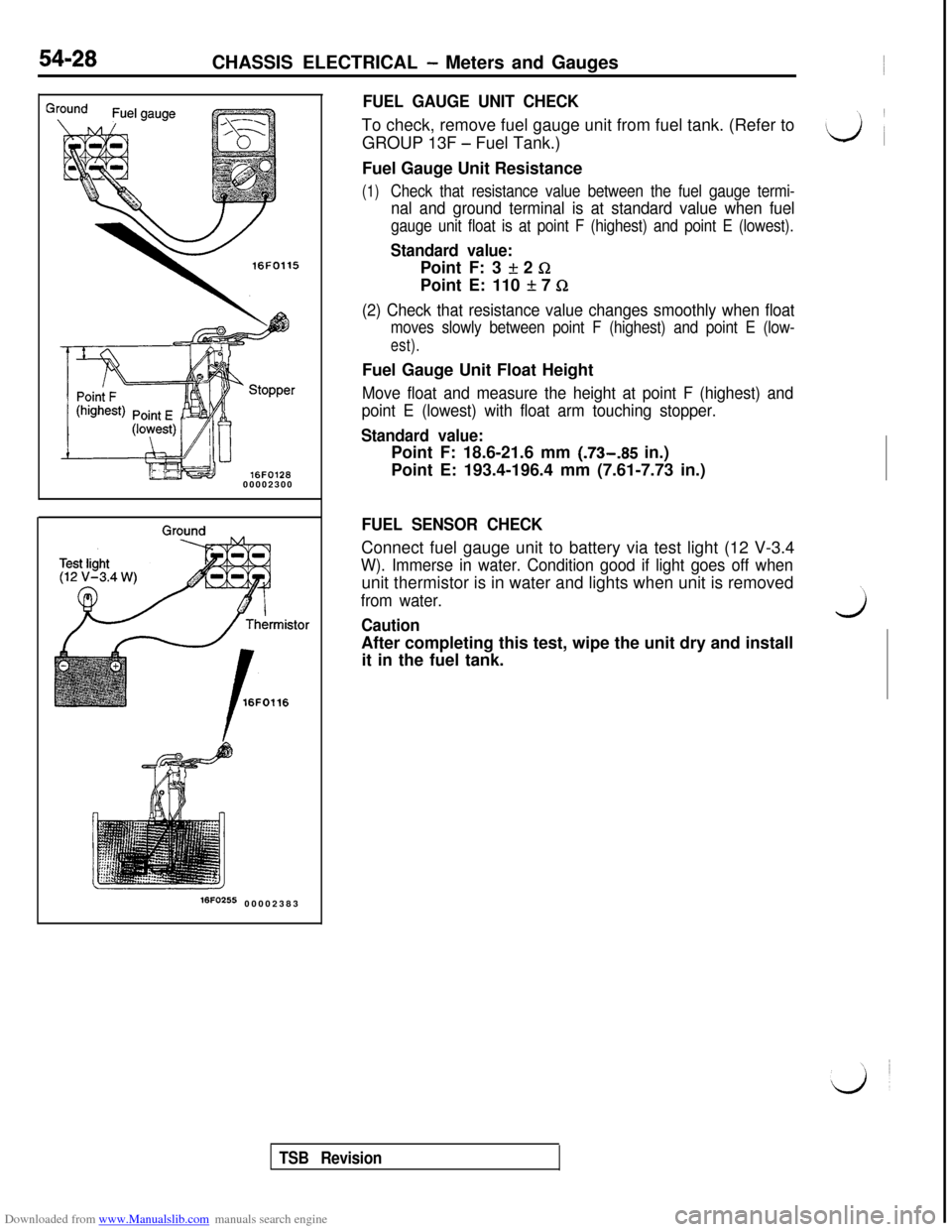
FUEL GAUGE UNIT CHECKTo check, remove fuel gauge unit from fuel tank. (Refer to
GROUP 13F
- Fuel Tank.)
Fuel Gauge Unit Resistance
(1)Check that resistance value between the fuel gauge termi-
nal and ground terminal is at standard value when fuel
gauge unit float is at point F (highest) and point E (lowest).
Standard value:Point F: 3
If: 2 GPoint E: 110
It 7 Q
(2) Check that resistance value changes smoothly when float
moves slowly between point F (highest) and point E (low-
est).Fuel Gauge Unit Float Height
Move float and measure the height at point F (highest) and
point E (lowest) with float arm touching stopper.
Standard value:Point F: 18.6-21.6 mm (.73-.85 in.)
Point E: 193.4-196.4 mm (7.61-7.73 in.)
FUEL SENSOR CHECKConnect fuel gauge unit to battery via test light (12 V-3.4
W). Immerse in water. Condition good if light goes off whenunit thermistor is in water and lights when unit is removed
from water.
CautionwAfter completing this test, wipe the unit dry and install
it in the fuel tank.
TSB Revision
Page 525 of 738
Downloaded from www.Manualslib.com manuals search engine CHASSIS ELECTRICAL - Meters and Gauaes
i
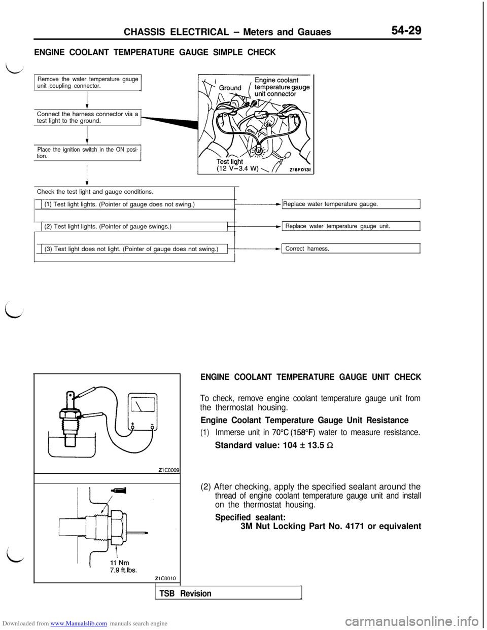
ENGINE COOLANT TEMPERATURE GAUGE SIMPLE CHECKConnect the harness connector via a
test light to the ground.
Remove the water temperature gauge
unit coupling connector.
t
Place the ignition switch in the ON posi-tion.
I
(12 v’3.4 w) \ //Z16FO13lCheck the test light and gauge conditions.
i(1) Test light lights. (Pointer of gauge does not swing.)_____c Replace water temperature gauge.
[ (2) Test light lights. (Pointer of gauge swings.)Replace water temperature gauge unit.
[ (3) Test light does not light. (Pointer of gauge does not swing.)/-------I Correct harness.
ENGINE COOLANT TEMPERATURE GAUGE UNIT CHECK
To check, remove engine coolant temperature gauge unit from
the thermostat housing.
Engine Coolant Temperature Gauge Unit Resistance
(1)Immerse unit in 70°C (158OF) water to measure resistance.Standard value: 104
f 13.5 Sz(2) After checking, apply the specified sealant around the
thread of engine coolant temperature gauge unit and install
on the thermostat housing.
Specified sealant:3M Nut Locking Part No. 4171 or equivalent
TSB RevisionI
Page 526 of 738
Downloaded from www.Manualslib.com manuals search engine 54-30CHASSIS ELECTRICAL - Meters and Gauges
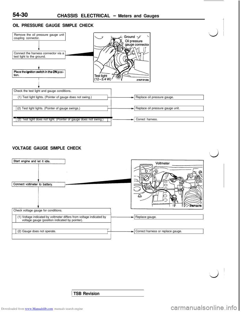
OIL PRESSURE GAUGE SIMPLE CHECKRemove the oil pressure gauge unit
coupling connector.Connect the harness connector via a
test light to the ground.
-1Place the ignition switch in the ON posi-Check the test light and gauge conditions.
(1) Test light lights. (Pointer of gauge does not swing.)
k-1 Replace oil pressure gauge.
1 (2) Test light lights. (Pointer of gauge swings.)k-1 Replace oil pressure gauge unit.
1 (2) Test light does not light. (Pointer of gauge does not swing.)/-1 Correct harness.
VOLTAGE GAUGE SIMPLE CHECKCheck voltage gauge for conditions.
(1) Voltage indicated by voltmeter differs from voltage indicated by
voltage gauge (position indicated by pointer).
-1 Replace gauge.
(2) Gauge does not operate.
/--I Correct harness or replace gauge.
1 TSB Revision
Page 532 of 738
Downloaded from www.Manualslib.com manuals search engine 54-36CHASSIS ELECTRICAL - Lighting System
SPECIAL TOOLS
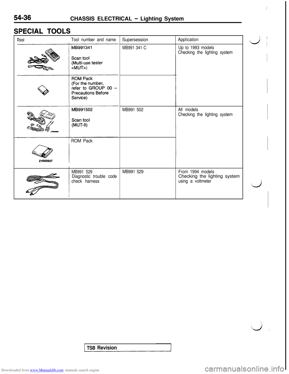
ToolTool number and name
1 ROM Pack
MB991 529Diagnostic trouble code
check harness
Supersession
MB991 341 C
Application
Up to 1993 models
Checking the lighting system
MB991 502All models
Checking the lighting system
MB991 529From 1994 modelsChecking the lighting system
using a voltmeter
I
‘, I
L/i
1
d
TSB Revision
Page 534 of 738
Downloaded from www.Manualslib.com manuals search engine CHASSIS ELECTRICAL - Liahting System
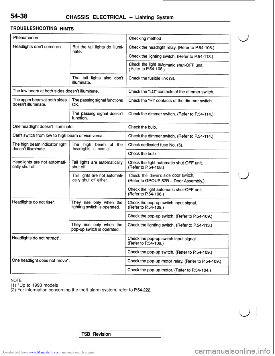
TROUBLESHOOTING
Check the light aut
Refer to
P.54-108.
headlights is normal.
Taillights are not automati-
Check the driver’ssidedoor switch.tally
shut off either.
NOTE(1) *Up to 1993 models
(2) For information concerning the theft-alarm system, refer to
P.54-222.
TSB Revision
Page 552 of 738
Downloaded from www.Manualslib.com manuals search engine INPUT SIGNALWith voltmeterData link connector
Ii ri7-11
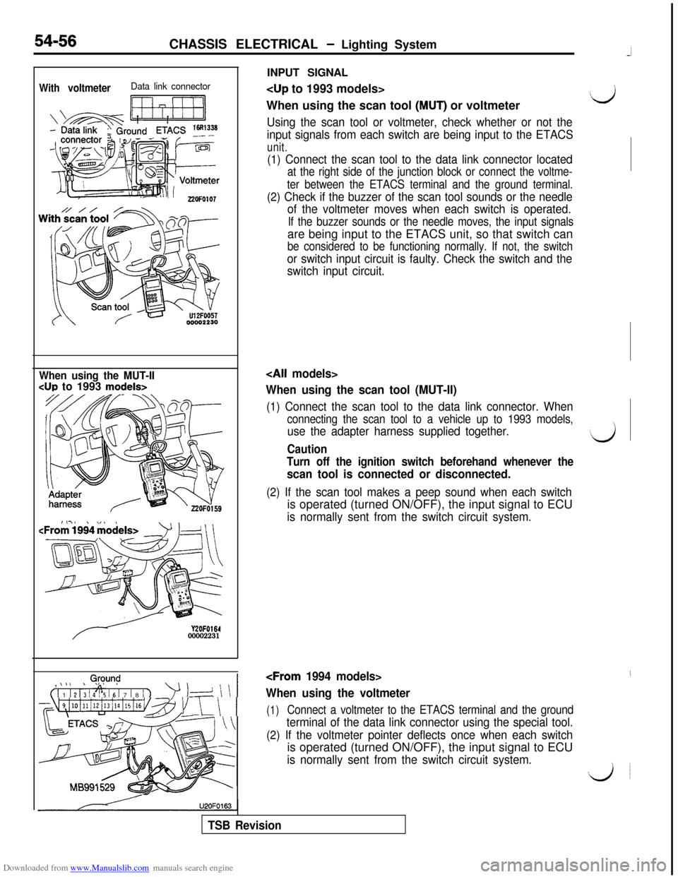
When using the scan tool (MUT) or voltmeter‘d
Using the scan tool or voltmeter, check whether or not the
input signals from each switch are being input to the ETACS
unit.
54-56CHASSIS ELECTRICAL - Lighting System
(1) Connect the scan tool to the data link connector located
at the right side of the junction block or connect the voltme-
ter between the ETACS terminal and the ground terminal.
(2) Check if the buzzer of the scan tool sounds or the needle
of the voltmeter moves when each switch is operated.
If the buzzer sounds or the needle moves, the input signalsare being input to the ETACS unit, so that switch can
be considered to be functioning normally. If not, the switch
or switch input circuit is faulty. Check the switch and the
switch input circuit.
When using the MUT-II
CUP to 1993 models>
Y2OFO16400002231,
0,@y.m$
( 1 1 1 2 1; 1 4% 16 1 7 1 8 / 1
’ 1-d \ \ 1
~~~4i10illi12i13illi15i16v~~~1 \ \ 1U2OFO163
When using the scan tool (MUT-II)
(1) Connect the scan tool to the data link connector. When
connecting the scan tool to a vehicle up to 1993 models,
use the adapter harness supplied together.‘dCaution
Turn off the ignition switch beforehand whenever the
scan tool is connected or disconnected.
(2) If the scan tool makes a peep sound when each switchis operated (turned ON/OFF), the input signal to ECU
is normally sent from the switch circuit system.
When using the voltmeter
(1)Connect a voltmeter to the ETACS terminal and the ground
terminal of the data link connector using the special tool.
(2) If the voltmeter pointer deflects once when each switchis operated (turned ON/OFF), the input signal to ECU
is normally sent from the switch circuit system.
do
TSB Revision
Page 558 of 738
Downloaded from www.Manualslib.com manuals search engine 54-62CHASSIS ELECTRICAL - Lighting System
OPERATION
lWhen the fog light switch is placed in the ON position with the lighting switch in the HEAD positionand the dimmer switch in the LO position, current flows through the dedicated fuse (4) to the coil
of the fog light relay, the fog light switch, the dimmer switch and ground, causing the contacts of
the fog light relay to close.
When the contacts of the fog light relay close, current flows through the dedicated fuse (4) to the
contacts of the fog light relay, the fog lights and ground, causing the fog lights to come on.
lWhen the dimmer switch is placed in the HI position or the lighting switch is placed in the TAIL or
OFF position while the fog lights are ON, current supply to the fog light relay or headlight relay is
cut off. As a result, the contacts of the fog light relay open, and the fog lights go out.
NOTE
The fog lights are included in the light automatic shut-OFF system. (Refer to P.54-37). The indicator lights
are also included in the same system.
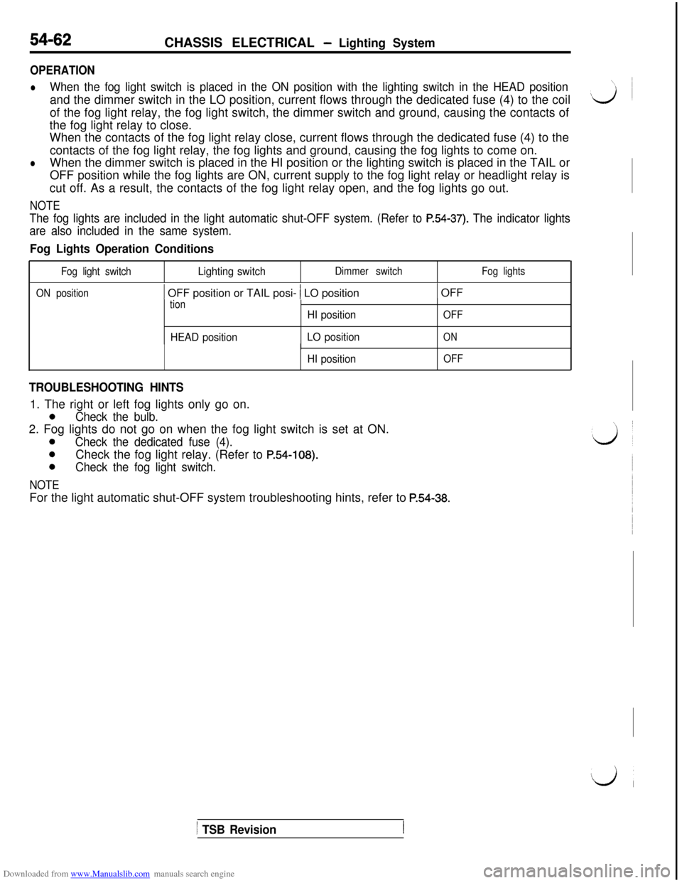
Fog Lights Operation Conditions
Fog light switchLighting switchDimmer switchFog lights
ON position
1 OFF position or TAIL posi- 1 LO position1 OFF
tion
HEAD positionHI position
LO position
OFF
ON
HI position
I
OFF
TROUBLESHOOTING HINTS1. The right or left fog lights only go on.
0Check the bulb.2. Fog lights do not go on when the fog light switch is set at ON.
0Check the dedicated fuse (4).
0Check the fog light relay. (Refer to P.54-108).
0Check the fog light switch.
NOTEFor the light automatic shut-OFF system troubleshooting hints, refer to
P.54-38.
1 TSB Revision