check engine light MITSUBISHI 3000GT 1992 2.G Service Manual
[x] Cancel search | Manufacturer: MITSUBISHI, Model Year: 1992, Model line: 3000GT, Model: MITSUBISHI 3000GT 1992 2.GPages: 738, PDF Size: 35.06 MB
Page 619 of 738
Downloaded from www.Manualslib.com manuals search engine LCHASSIS ELECTRICAL
- Cigarette Lighter
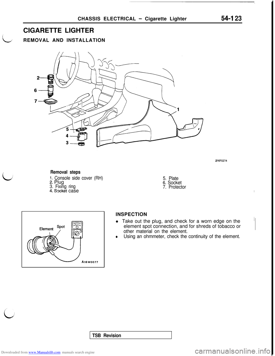
CIGARETTE LIGHTER
REMOVAL AND INSTALLATION54-I 23
i,
216FO274
Removal steps
1. Console side cover (RH)2. Plug3. Fixing ring4. Socket case
5. Plate6. Socket7. ProtectorINSPECTION
l Take out the plug, and check for a worn edge on the
element spot connection, and for shreds of tobacco or
other material on the element.
lUsing an ohmmeter, check the continuity of the element.
TSB Revision
Page 658 of 738
Downloaded from www.Manualslib.com manuals search engine 54-I 62CHASSIS ELECTRICAL - Radio and Tape Player
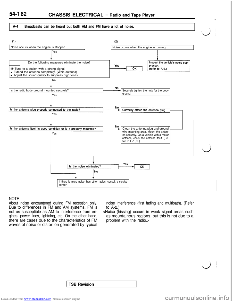
A-4
Broadcasts can be heard but both AM and FM have a lot of noise.
(1)Noise occurs when the engine is stopped.
YesJ
(2)Noise occurs when the engine in running.
Do the following measures eliminate the noise?
@ Tune to a station with a strong signal.
l Extend the antenna completely. (Whip antenna)
l Adjust the sound quality to suppress high tones.
NoIs the radio body ground mounted securely?
Yes
Securely tighten the nuts for the bodyground.
Yes
YesClean the antenna plug and ground
wire mounting area. Mount the anten-
na securely. On a vehicle with a motor
antenna, check the antenna itself. (Re-fer to E-1, 2.)
If there is more noise than other radios, consult a servicecenter
NOTE
About noise encountered during FM reception only.
Due to differences in FM and AM systems, FM is
noise interference (first fading and multipath). (Refer
to A-2.)
not as susceptible as AM to interference from en-
gines, power lines, lightning, etc. On the other hand,
TSB Revision
Page 659 of 738
Downloaded from www.Manualslib.com manuals search engine CHASSIS ELECTRICAL - Radio and Tape Plavers54-163 ~
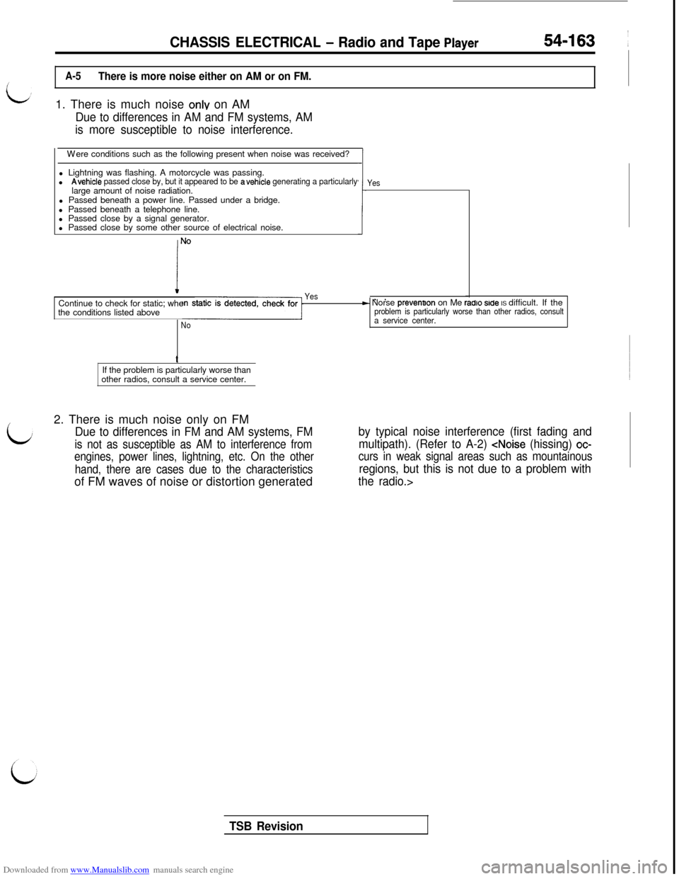
A-5There is more noise either on AM or on FM.1. There is much noise
onlv on AM
Due to differences in AM and FM systems, AM
is more susceptible to noise interference.Were conditions such as the following present when noise was received?
l Lightning was flashing. A motorcycle was passing.
l
Avehicle passed close by, but it appeared to be avehicle generating a particularlylarge amount of noise radiation.
l Passed beneath a power line. Passed under a bridge.
l Passed beneath a telephone line.
l Passed close by a signal generator.
l Passed close by some other source of electrical noise.
.I-!
I
NO
Yes
. .F- Norse prevenoon on Me radro srde IS difficult. If theproblem is particularly worse than other radios, consulta service center.Continue to check for static; whe
the conditions listed aboveNoYest
If the problem is particularly worse than
other radios, consult a service center.
2. There is much noise only on FM
Due to differences in FM and AM systems, FM
is not as susceptible as AM to interference from
engines, power lines, lightning, etc. On the other
hand, there are cases due to the characteristicsof FM waves of noise or distortion generated
by typical noise interference (first fading and
multipath). (Refer to A-2)
regions, but this is not due to a problem with
the radio.>
TSB Revision
Page 663 of 738
Downloaded from www.Manualslib.com manuals search engine CHASSIS ELECTRICAL - Radio and Tape Player54-167
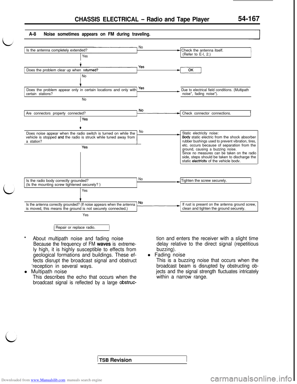
A-8Noise sometimes appears on FM during traveling.
NoIs the antenna completely extended?
Yes
t Check the antenna itself.
(Refer to E-l, 2.)
+Does the problem clear up whenre
1 No
Yes
iDoes the problem appear only in certain locations and only with yes
certain stations?
No
~ Due to electrical field conditions. (Multipath
noise*, fading noise*).
Are connectors property connected?
Yes
Check connector connections.1
tDoes noise appear when the radio switch is turned on while the
vehicle is stopped
and the radio is struck while tuned away froma station?
Yes
No*Static electricity noise:Sody static electric from the shock absorberrubber bushings used to prevent vibration, tires,etc. occurs because of separation from the
ground, causing a buzzing noise.
Since no measures can be taken on the radioside, steps should be taken to discharge the
static
electricitv of the vehicle bodv.
Is the radio body correctly grounded?
No(Is the mounting screw tightened securely?
)
Yes
-) Tighten the screw securely.I
Is the antenna correctly grounded? (If noise appears when the antennais moved, this means the ground is not securely connected.)
Yes
If rust is present on the antenna ground screw,clean and tighten the ground securely.
*
1 Repair or replace radio.1
About multipath noise and fading noise
Because the frequency of FM waves is extreme-
ly high, it is highly susceptible to effects from
geological formations and buildings. These ef-
fects disrupt the broadcast signal and obstruct
‘reception in several ways.l Multipath noise
This describes the echo that occurs when the
broadcast signal is reflected by a large obstruc-
tion and enters the receiver with a slight time
delay relative to the direct signal (repetitious
buzzing).l Fading noise
This is a buzzing noise that occurs when the
broadcast beam is disrupted by obstructing ob-
jects and the signal strength fluctuates intricately
within a narrow range.
1 TSB Revision
Page 686 of 738
Downloaded from www.Manualslib.com manuals search engine CHASSIS ELECTRICAL - Radio and Tape Player
Ring nut
Tbothsideofrack cable
Rack cable
16LO42700002407,8Loa1
7
Tooth side of rack cable
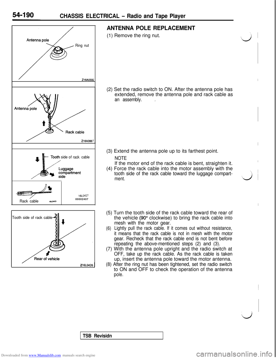
ANTENNA POLE REPLACEMENT(1) Remove the ring nut.
(2) Set the radio switch to ON. After the antenna pole has
extended, remove the antenna pole and rack cable as
an assembly._.(3) Extend the antenna pole up to its farthest point.
NOTEIf the motor end of the rack cable is bent, straighten it.
(4) Force the rack cable into the motor assembly with the
tooth side of the rack cable toward the luggage compart-
ment.(5) Turn the tooth side of the rack cable toward the rear of
the vehicle
(90” clockwise) to bring the rack cable into
mesh with the motor gear.
(6)Lightly pull the rack cable. If it comes out without resistance,
it means that the rack cable is not in mesh with the motor
gear. Recheck that the rack cable end is not bent before
repeating the above-mentioned steps (2) and (3).(7) With the antenna pole upright and the radio switch at
OFF, take up the rack cable. As the rack cable is takenup, insert the antenna pole toward the motor antenna.
(8) After the ring nut has been tightened, set the radio switchto ON and OFF to check the operation of the antenna
pole.
I
I
I
vi ~
I~
d
TSB Revisidn
Page 717 of 738
Downloaded from www.Manualslib.com manuals search engine iCHASSIS ELECTRICAL
- Theft-alarm Svstem54-221
(Output)Voltmeter rvv 1-1
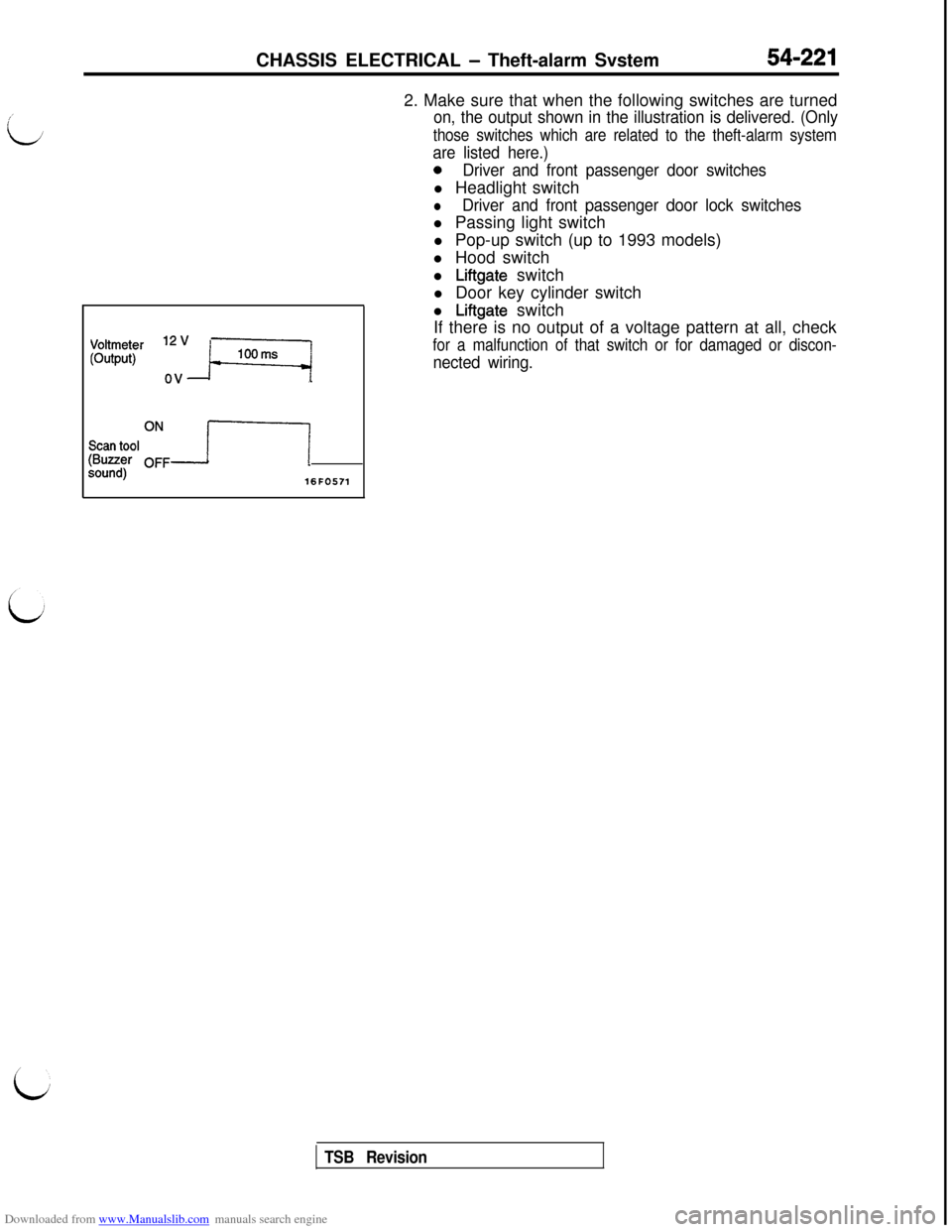
Scan tool(Buzzer %,isound)16FO5712. Make sure that when the following switches are turned
on, the output shown in the illustration is delivered. (Only
those switches which are related to the theft-alarm system
are listed here.)
0Driver and front passenger door switchesl Headlight switch
lDriver and front passenger door lock switchesl Passing light switch
l Pop-up switch (up to 1993 models)
l Hood switch
l
Liftgate switch
l Door key cylinder switch
l
Liftgate switch
If there is no output of a voltage pattern at all, check
for a malfunction of that switch or for damaged or discon-
nected wiring.
TSB Revision
Page 718 of 738
Downloaded from www.Manualslib.com manuals search engine 54-222CHASSIS ELECTRICAL - Theft-alarm System
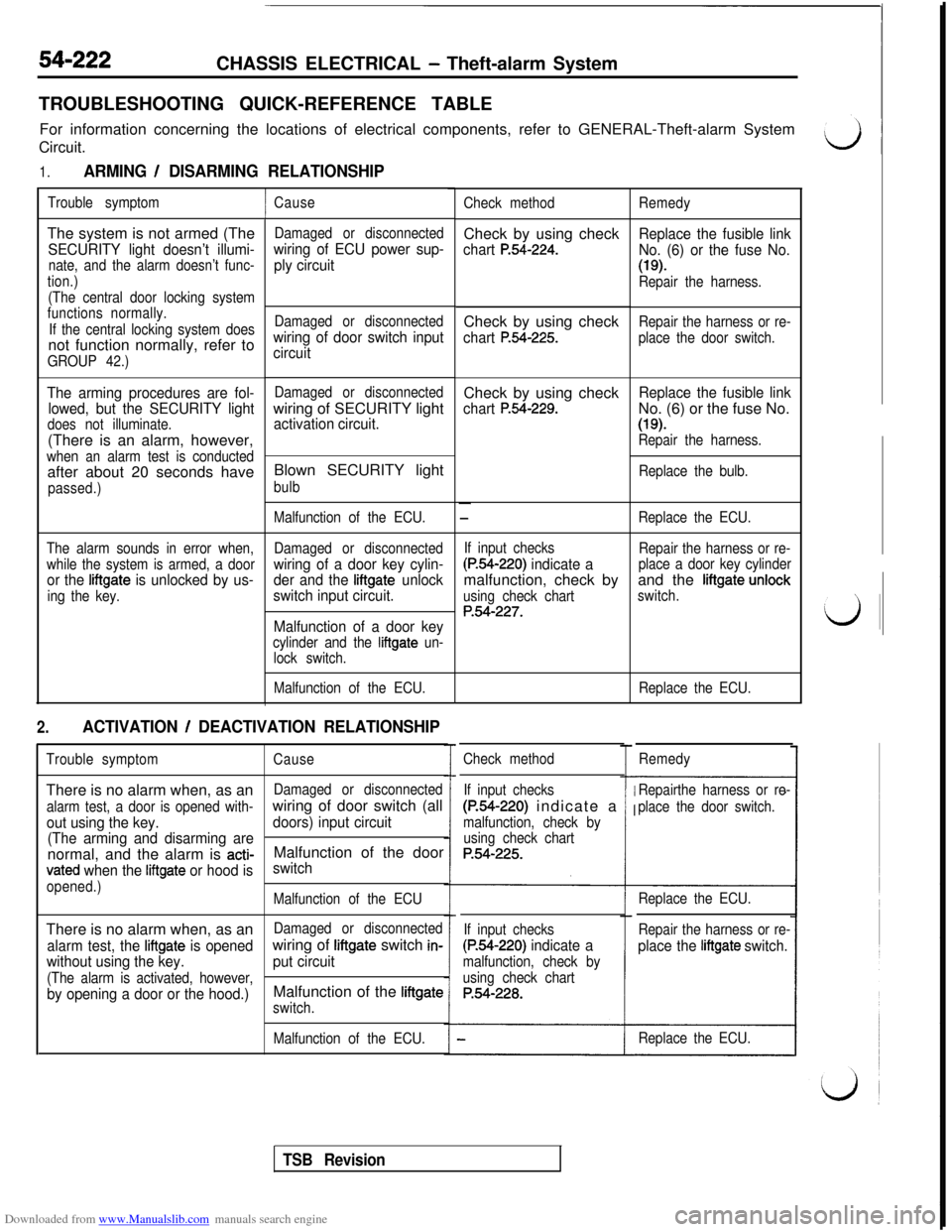
TROUBLESHOOTING QUICK-REFERENCE TABLE
For information concerning the locations of electrical components, refer to GENERAL-Theft-alarm System
Circuit.
1.ARMING / DISARMING RELATIONSHIP
Trouble symptomThe system is not armed (The
SECURITY light doesn’t illumi-
nate, and the alarm doesn’t func-
tion.)
(The central door locking system
functions normally.
If the central locking system doesnot function normally, refer to
GROUP 42.)
The arming procedures are fol-
lowed, but the SECURITY light
does not illuminate.(There is an alarm, however,
when an alarm test is conductedafter about 20 seconds have
passed.)
The alarm sounds in error when,
while the system is armed, a door
or the liftgate is unlocked by us-
ing the key.
ICause
Damaged or disconnected
wiring of ECU power sup-
ply circuit
Damaged or disconnected
wiring of door switch input
circuit
Damaged or disconnectedwiring of SECURITY light
activation circuit.Blown SECURITY light
bulb
Malfunction of the ECU.
Damaged or disconnected
wiring of a door key cylin-
der and the
liftgate unlock
switch input circuit.
Malfunction of a door key
cylinder and the liftgate un-
lock switch.
Malfunction of the ECU.
2.ACTIVATION / DEACTIVATION RELATIONSHIP
Trouble symptomCauseThere is no alarm when, as an
Damaged or disconnected
alarm test, a door is opened with-wiring of door switch (all
out using the key.doors) input circuit
(The arming and disarming arenormal, and the alarm is
acti-Malfunction of the door
vated when the liftgate or hood isswitch
opened.)
Malfunction of the ECUThere is no alarm when, as an
Damaged or disconnected
alarm test, the liftgate is opened
without using the key.wiring of liftgate switch in-
put circuit
(The alarm is activated, however,
by opening a door or the hood.)Malfunction of the liftgate
switch.
Malfunction of the ECU.Check methodCheck by using check
chart P.54-224.Check by using check
chart P.54-225.Check by using check
chart P.54-229.
If input checks
(P.54-220) indicate amalfunction, check by
using check chart
P&f-227.
Check method
If input checks
(P.54-220) indicate a
malfunction, check by
using check chart
P.54-225.
If input checks
(P.54-220) indicate a
malfunction, check by
using check chart
P.54-228.
Remedy
Replace the fusible link
No. (6) or the fuse No.
(19).Repair the harness.
Repair the harness or re-
place the door switch.
Replace the fusible linkNo. (6) or the fuse No.(1%
Repair the harness.
Replace the bulb.
Replace the ECU.
Repair the harness or re-
place a door key cylinderand the
liftgate unlock
switch.
Replace the ECU.
Remedy
Repairthe harness or re-
place the door switch.
Replace the ECU.
Repair the harness or re-
place the liftgate switch.
Replace the ECU.
TSB Revision
Page 719 of 738
Downloaded from www.Manualslib.com manuals search engine CHASSIS ELECTRICAL - Theft-alarm System54-223
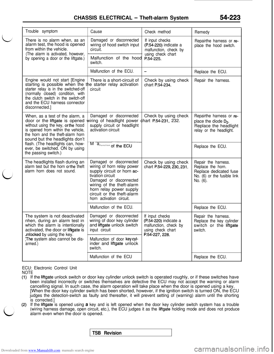
Trouble symptom
Cause
Check method
Remedy
There is no alarm when, as analarm test, the hood is openedDamaged or disconnected
wiring of hood switch input
If input checks
Repairthe harness or re-
from within the vehicle.circuit.
(P.54-220) indicate aplace the hood switch.
(The alarm is activated, however,malfunction, check by
I
by opening a door or the liftgate.)using check chartMalfunction of the hood p.54-225.
switch.
Malfunction of the ECU.
-Replace the ECU.
Engine would not start [EngineThere is a short-circuit of
starting is possible when the the starter relay activationCheck by using check
chart P.54-234.
Repair the harness.
starter relay is in the switched-off
circuit
(normally closed) condition, with
the clutch switch in the switch-off
and the ECU harness connector
disconnected.]
When, as a test of the alarm, aDamaged or disconnectedCheck by using check
door or the
liftgate is opened wiring of headlight power chart P.54-231, 232.
Repairthe harness or re-
without using the key, orthe hood
is opened from within the vehicle,supply circuit or headlightplace the diode Ds.
activation circuitReplace the headlight
the horn and the theft-alarm hornrelay or the headlight.sound but the headlights don’t
flash. (The headlights can, how-
ever, be switched. ON by usingMa
lfunction of the ECUReplace the ECU.
the passing switch.)The headlights flash during an
alarm test but the horn orthe theftDamaged or disconnectedCheck by using checkRepair the harness.
alarm horn does not sound.wiring of horn relay power
chart P.54-229,230,231.supply circuit or horn ac-Replace the horn.
tivation circuitReplace dedicated fuse
Damaged or disconnectedNo. (6) or the fusible linkwiring of the theft-alarmNo. (6).horn relay power supply
circuit or the theft-alarm
horn activation circuit.
Malfunction of the ECU.
Replace the ECU.The system is not deactivated
nhen, during an alarm test in
Damaged or disconnected
If input checks
which the alarm is intentionallywiring of door key cylinder
Repair the harness.activated, the door or
liftgate isand
liftgate unlock switch(P.54-220) indicate a
input circuitmalfunction, check byReplace the key cylinder
Jnlocked by using the key.
using check chartswitch or the
liftgate
switch.
:The system also cannot be dis-P.54-227,228.
armed.)
Malfunction of door keycyl-inder and liftgate unlock
switch.
Malfunction of the ECU
Replace the ECU.
ECU: Electronic Control Unit
NOTEIf the
lifigate unlock switch or door key cylinder unlock switch is operated roughly, or if these switches have
been installed incorrectly or switches themselves are defective the ECU may not accept the warning or alarmcancelling signal. In such case, the alarm operation will take place when the door is opened using a key.
[When the door key cylinder switch has been shorted, however, if the ignition switch is turned ON, the ECU
judges the detection-switch as faulty and thereafter, it will prevent setting of (warning) alarm until the shorting
is corrected.]
If the
liftgate is opened using a key and is left opened when the door key cylinder switch system has a trouble
(wiring harness damage, open circuit, etc.), the ECU judges it as the
liftgate holding mode and does not producealarm even when the door is opened.
TSB Revision
Page 725 of 738
Downloaded from www.Manualslib.com manuals search engine iCHASSIS ELECTRICAL
- Theft-alarm System54-229
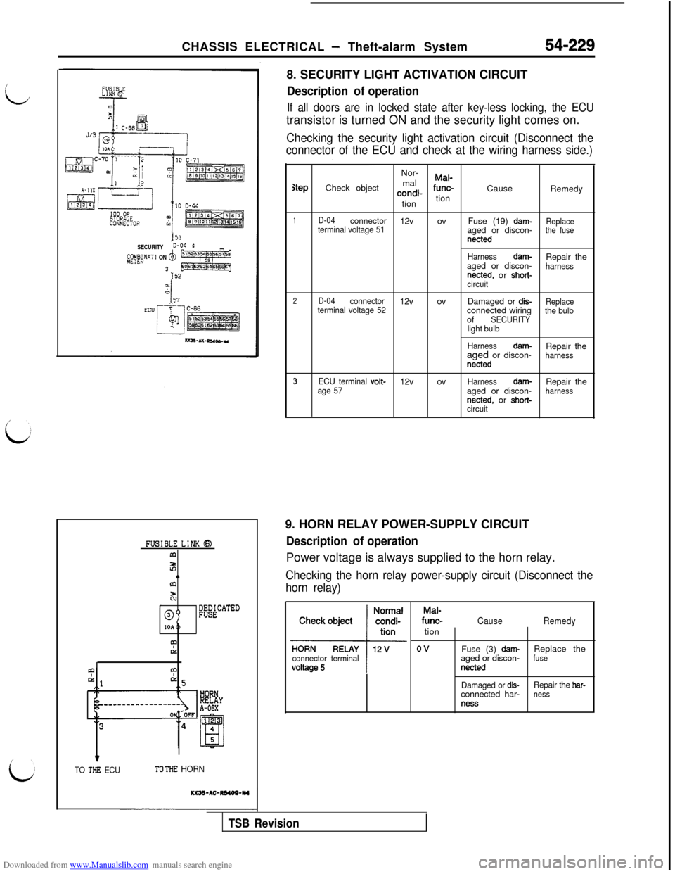
JS!SECURITYE-04@y&fiNAT! ON .$36
152
FUSIBLE LINK CE)m
z0alz!
r%BECATED
mCL
1
TO THE ECUTO THE HORN8. SECURITY LIGHT ACTIVATION CIRCUIT
Description of operation
If all doors are in locked state after key-less locking, the ECUtransistor is turned ON and the security light comes on.
Checking the security light activation circuit (Disconnect the
connector of the ECU and check at the wiring harness side.)Nor-
malMal-
stepCheck objectcondi-func-
Cause
Remedy
tiontion
1D-04connector12v ovterminal voltage 51Fuse (19) dam-Replaceaged or discon-the fusenetted
Harnessdam-Repair the
aged or discon-harnessnetted, or short-circuit
2D-04connector12v ovterminal voltage 52Damaged or dis-
Replaceconnected wiringthe bulbofSECURITYlight bulb
Harness
dam-Repair the
aged or discon-harnessnetted
3ECU terminal volt-12v ovHarnessdam-
age 57Repair the
aged or discon-harnessnetted, or short-circuit9. HORN RELAY POWER-SUPPLY CIRCUIT
Description of operationPower voltage is always supplied to the horn relay.
Checking the horn relay power-supply circuit (Disconnect the
horn relay)
connector terminal
Mal-func-CauseRemedytion
Fuse (3)
dam-Replace the
aged or discon-fusenetted
Damaged or dis-Repair the har-connected har-nessness
TSB Revision
Page 727 of 738
Downloaded from www.Manualslib.com manuals search engine i
LCHASSIS ELECTRICAL
- Theft-alarm System54-231
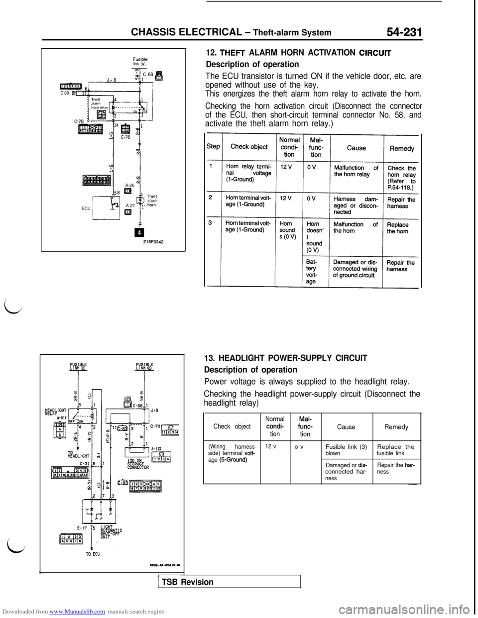
Fwbklink (6)A-26
8=’ Theft-
alarm
ECUA 27
i
1 *horn
al
Z16FO342
TO Ecu
auO-U-RS4I2-YI
12. THEFT ALARM HORN ACTIVATION ClRCUlT
Description of operation
The ECU transistor is turned ON if the vehicle door, etc. are
opened without use of the key.
This energizes the theft alarm horn relay to activate the horn.
Checking the horn activation circuit (Disconnect the connector
of the ECU, then short-circuit terminal connector No. 58, and
activate the theft alarm horn relay.)
13. HEADLIGHT POWER-SUPPLY CIRCUIT
Description of operation
Power voltage is always supplied to the headlight relay.
Checking the headlight power-supply circuit (Disconnect the
headlight relay)
Check objectNormalMal-condi-func-CausetiontionRemedy
(Wiring
harness12 vovside) terminal volt-Fusible link (3)Replace theblownfusible link
age (5-Ground)Damaged or dis-Repair the har-connected har-nessness
1 TSB Revision