headlight MITSUBISHI 3000GT 1992 2.G Owner's Manual
[x] Cancel search | Manufacturer: MITSUBISHI, Model Year: 1992, Model line: 3000GT, Model: MITSUBISHI 3000GT 1992 2.GPages: 738, PDF Size: 35.06 MB
Page 202 of 738
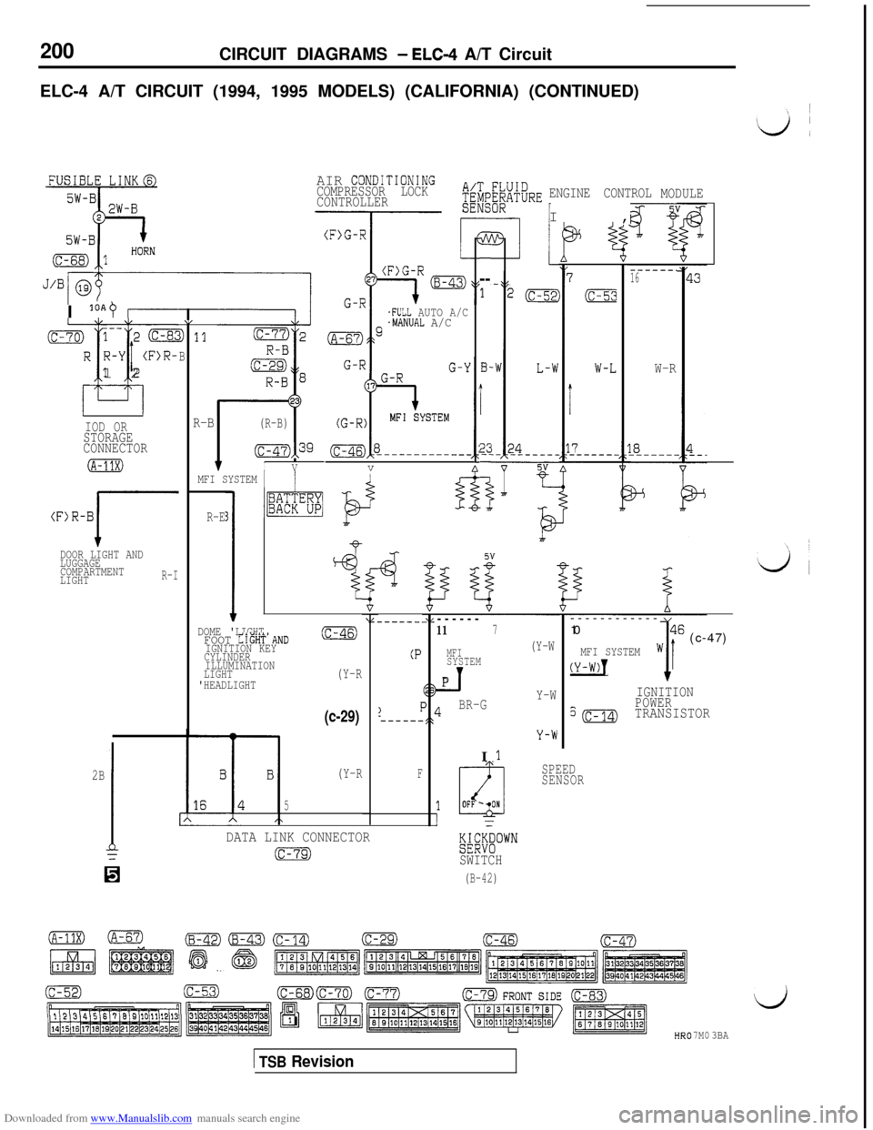
Downloaded from www.Manualslib.com manuals search engine 200CIRCUIT DIAGRAMS - ELC-4 A/T Circuit
ELC-4 A/T CIRCUIT (1994, 1995 MODELS) (CALIFORNIA) (CONTINUED)
AIR CONDiTIONINGCOMPRESSOR LOCK
CONTROLLERENGINE CONTROLI,MODULE
3---
1
B-
i
2;-
i
7
SW-RI +
------.16
W-RI
loAO I.FULL AUTO A/C.MANUAL A/C
v(c-70) 1-- 2 (c-8cR R-Y
(F>R-
T-i
i12
1,
D 11
B
R-B(R-B)
(c-47),39
fIV
IOD ORSTORAGE
CONNECTOR
(A-11X)MFI SYSTEM 1/
(F)R-B
JDOOR LIGHT AND
LUGGAGE
COMPARTMENT
LIGHT
R-I
R-E3
1
I1~%“BF
4
l-
“i------
117
MFI(Y-W
SYSTEM
_TPI
BR-GY-W------------
10
w46 (c-47)MFI SYSTEM
(Y-W)!1I
IGNITION
?(c-14)
POWERTRANSISTOR
DOME 'LIGHTFOOT LIGHT'AND(c-46)
IGNITION KEY
CYLINDER
ILLUMINATION
LIGHT
(Y-R'HEADLIGHT
(P
(c-29)
2B
1=
SPEED
SENSOR(Y-RF
5
DATA LINK CONNECTOR
(c-79)%%““”SWITCH
(B-42)H
7M03BA
1 TSB Revision
Page 219 of 738
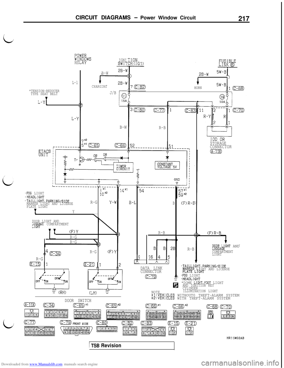
Downloaded from www.Manualslib.com manuals search engine CIRCUIT DIAGRAMS - Power Window Circuit217
i
3REIGNISWI?
B-W2B-b
CHARGING
J/B
2B-W5W-Bl
HORN5W-B,1-i\ 1
L-l
*TENSION-REDUCER
TYPE SEAT BELT
L-Y1
B-WR-B
STORAGE
CONNECTOR
(A-11X)
51-------1
L-------------_---y_-_____
8:1.FOG LIGHT.HEADLIGHT1oz2
.TAILLIGHT,PARKING/SIDE
MARKER LIGHT AND LICENSER-GY-WPLATE LIGHT
'IY
\DOOR LIGHT AND/gG&GE COMPARTMENT
TT
(F)Y
R-G
R-G
3,4mR-G(F)Y
R-G
(E-15)1(E-21)1
IAI II
(F)R-E
14:'
B
R-B(F)R-B
R-B@zA&GHT AND
COMPARTMENT
LIGHT
.TAILLI
!%ER
GHl
L!i
',PARKING/SIDEGHT AND LICENSE:HTDATA LINK
CONNECTOR
(c-79).FOG LIGHT
Ii
.HEADLIGHT*DOME LIGHTSFOOT LIGHTAND IGNITION KEY
CYLINDER
NOTEILLUMINATION LIGHTxl:VEHICLES WITHOUT0 THEFT-ALARM SYSTEM:2:VEHICLES WITH THEFT-ALARM SYSTEM
3=
(RH)(LH) =
B-.L
DOOR SWITCH
(A-11X)-(c-65):'(c-65):2(c-68)
q
El1(c-70)m1234
HRllM02AB
1 TSB Revision
Page 221 of 738
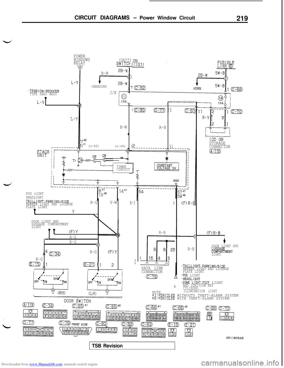
Downloaded from www.Manualslib.com manuals search engine CIRCUIT DIAGRAMS - Power Window Circuit
219
POWER
WINDOWS
RELAYIGNITI
A
I
SWITCl
B-W2B-r,
L-'y'rCHARGING
J/B.TENSION-REDUCER
TYPE SEAT BELT
L-Y1
L-‘i
B-W
722
jzl (c-65)
(c-66)u
I
TIMER1CIRCUIT/1
\,
I(c-80) (c-77)“1(c-8:!
R-B
j251‘----------------------~
FOG LIGHT
HEADLIGHT
TAILLIGHT,PARKING/SIDE
MARKER LIGHT AND LICENSER-GY-WB-IPLATE LIGHT
IY
\DOOR LIGHT AND
LUGGAGE COMPARTMENT
LIGHT
1'
(F)Y
R-G
R-G
$2
s&gR-G(F>Y
R-G
(E-15),1/t(E-21)1 2 [
II /I
E(F)R-E
R-B
R-B(F>R-BI
tDOOR LIGHT
~X%@MENT
AND
LIGHT
DATA LINK
CONNECTOR
@gT2J
.TAILLIGHT,PARKING/SIDEMARKER LIGHT AND LICENSE
PLATE LIGHT
.FOG LIGHT6.HEADLIGHT.DOME LIGHTsFOOT LIGHTAND IGNITION KEYCYLINDERNOTEILLUMINATION LIGHTxl:VEHICLES WITHOUT0 THEFT-ALARM SYSTEM:2:VEHICLES WITH THEFT-ALARM SYSTEM
IODSTORAGE
CONNECTOR
(A-11X)
HRllMOGAB
TSB Revision
Page 379 of 738
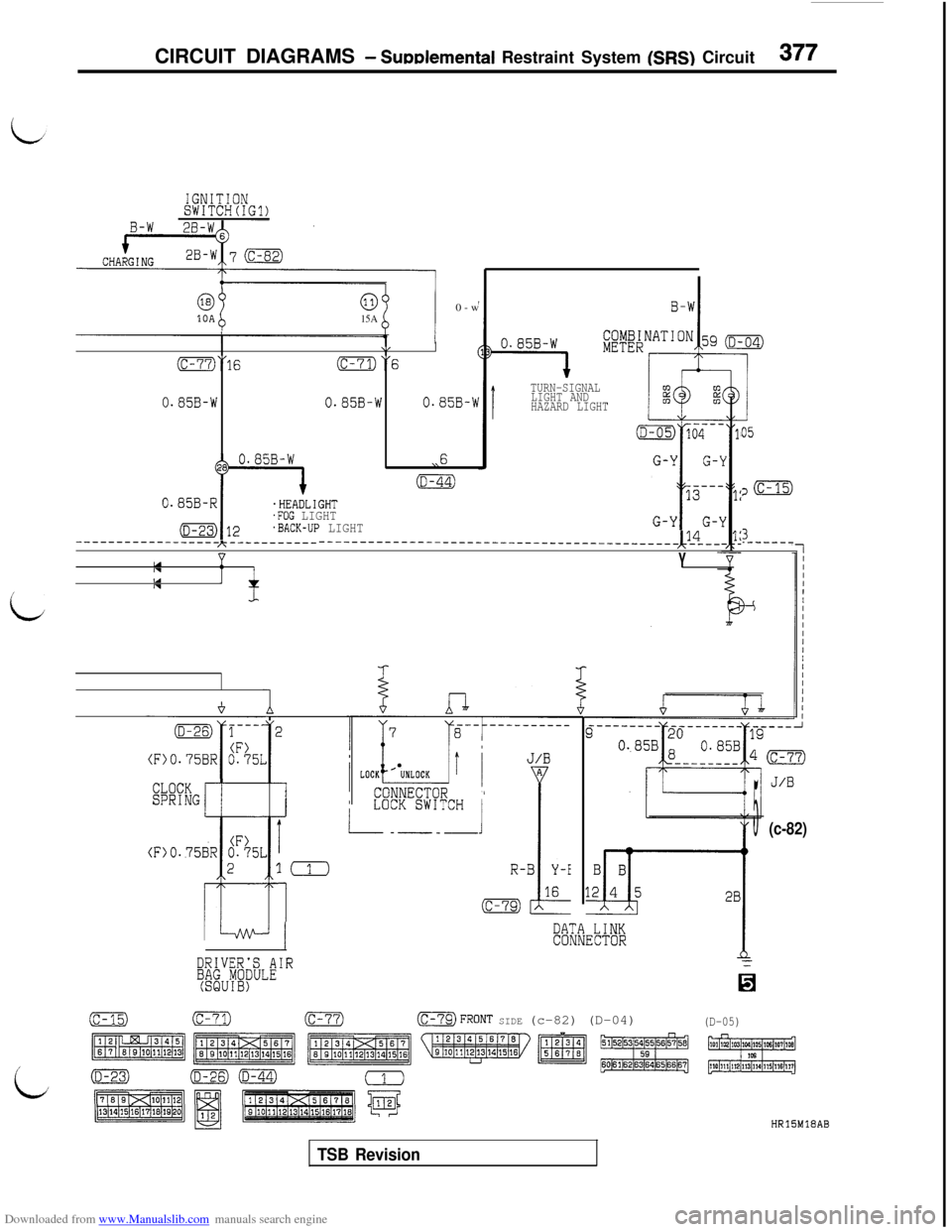
Downloaded from www.Manualslib.com manuals search engine CIRCUIT DIAGRAMS - Sudemental Restraint System (SRS) Circuit377
IGNITIONSWITCH(IG1)
i
i
63
%
00-w10A15A
\,I
0“16(c-71)“6 '
0.85B-W0.85B-W0.85B-W
,,6
(D-44)
0.85B-R
I
.HEADLIGHT.FOG LIGHT
(D-25) 12.BACK-UP LIGHT------------------h-------------__---- ------- - ------- - ----- ---------------&4--nYuInIAnJ
TURN-SIGNAL
LIGHT AND
HAZARD LIGHT
a-
:3
CLOCKSPRINGr-l-
5
4
I,
CONNECTOR 1LOCK SWITCH
I
--_-
>
I(1
1DATA LINKCONNECTOR
DRIVER'S AIR;MU~f~ULE0
05
:,m
3.------
(c-82)
(c-15)(c-71)(c-77)-FRONT SIDE (c-82) (D-04)(D-05)
HRlSM18AB
TSB Revision
Page 426 of 738
Downloaded from www.Manualslib.com manuals search engine 424
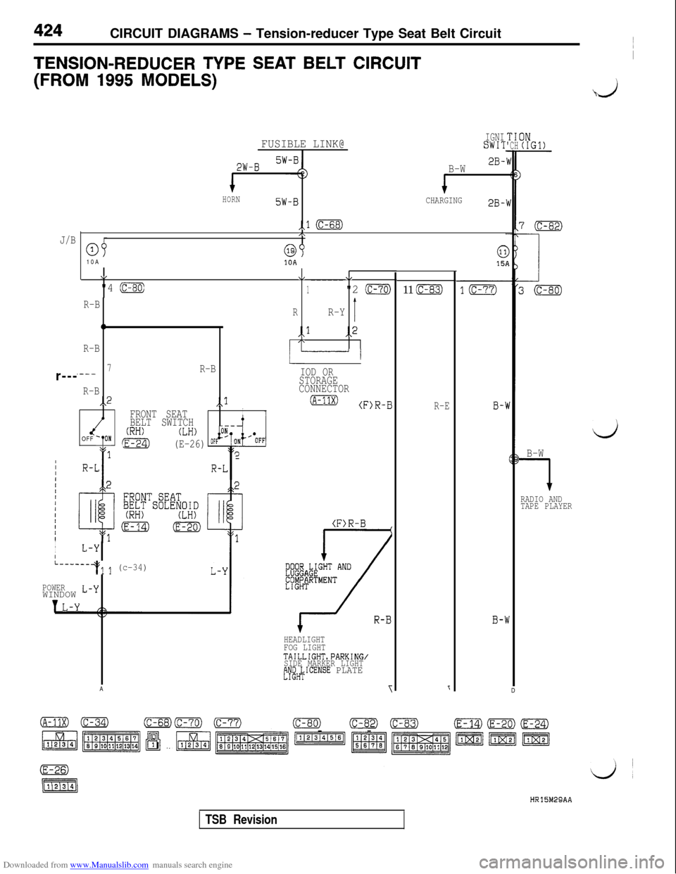
CIRCUIT DIAGRAMS - Tension-reducer Type Seat Belt Circuit
TENSION-REDUCER TYPE SEAT BELT CIRCUITI
(FROM 1995 MODELS)
&Ij
FUSIBLE LINK@IGNISWIT
2W-BB-W2B-
HORN5W-BCHARGING2B-
,.l (c-68)
J/B/\
a3r---10A10A
VV\I
"4 (c-80)------1"2 (c-70)
R-BRR-YI0,,l,,2
R-B
I“------I
7R-B.---
R-B,,2,,l
FRONT SEATI1BELT SWITCH(RH)OFF 'TON
71
!E-24)
(LH) p"-
(E-26) oFFI(
IIIR-L1
I
I1-YI
L------+l 1 (c-34)
POWERWINDOW L-yA
IOD ORSTORAGE
CONNECTOR
(A-11X)(F)R-B
HEADLIGHT
FOG LIGHT
TAILLIGHT.PARKING/
SIDE MARKER LIGHT
tYeH$ICENSE PLATE
11 (c-83)
R-EB-'
B-'
TICIN'CH(IGl)
blD
d
B-W
1
RADIO AND
TAPE PLAYER
HR15M29AA
TSB Revision
Page 427 of 738
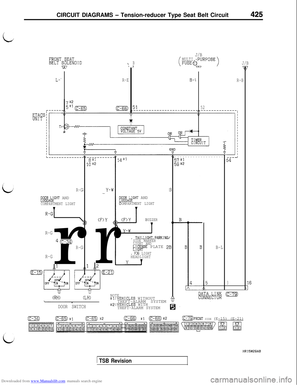
Downloaded from www.Manualslib.com manuals search engine CIRCUIT DIAGRAMS - Tension-reducer Type Seat Belt Circuit425
id
J/B;EATILENOIDi7‘
MULTI.BFUSEC7
B-\
LJRPOSE)J/B
R-B
52 R-E
3-------------------
i7%1
/
iJR-G
$l$A&GHT AND
COMPARTMENT LIGHT
R-G1 \
R-Gr
Q(c-34)
R-G
R-G
Y-h-E
iEgAk;GHT AND
OMPARTMENT LIGHT
BUZZER
I
(F)Y
r
B
I
. TAILLIGHT.PARKING/SIDE MARKER
LIGHT AND
EjgfiFSE PLATE 2EB-L
5
I. FOG LIGHTHEADLIGHT
Iy
-
(RH<(LH;NOTE:l:VEHICLES WITHOUTTHEFT-ALARM SYSTEM =
DOOR SWITCH:E:VEHICLES WITHTHEFT-ALARM SYSTEMIs-
(c-34)(c-65) $1m :2(c-66) :1 (c-66):2OFRONT SIDE (E-15) (E-21)
HRl5M29AB
1 TSB Revision
Page 433 of 738
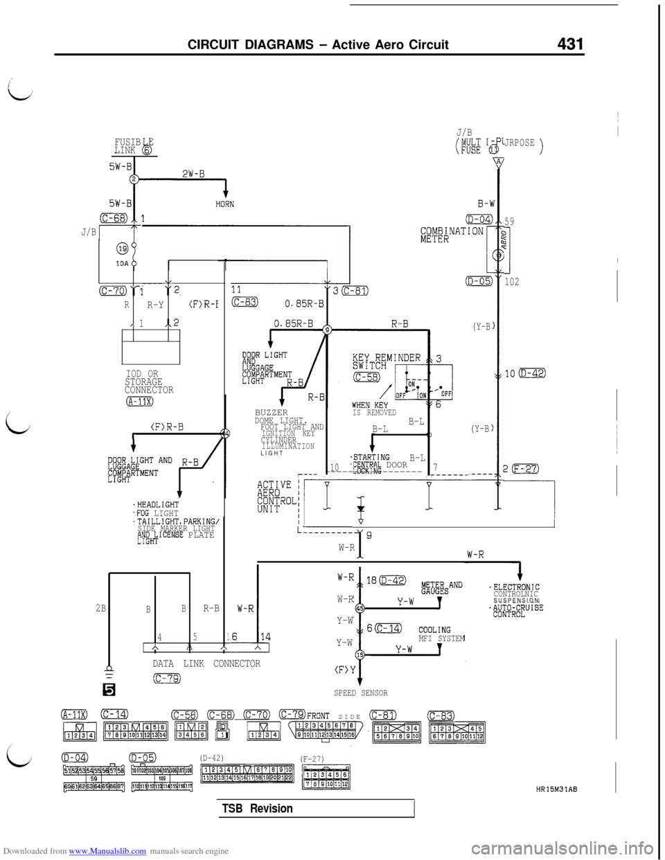
Downloaded from www.Manualslib.com manuals search engine CIRCUIT DIAGRAMS - Active Aero Circuit431
FUSIB E
LINK 6b
J/B
i
@
10A
\,----(c-70)‘1 “2.
RR-Y(F)R-I
,\ 1,.2
IOD ORSTORAGE
CONNECTOR
(F)R-Br
'HEADLIGHT.FOG LIGHT'TAILLIGHTsPARKING,SIDE MARKER LIGHTtjW&ICENSE PLATE
J/B
(WE 'e
BUZZERIS REMOVEDDOME LIGHT.FOOT LIGHT ANDB-L
IGNITION KEYB-LCYLINDER10ILLUMINATIONLIGHT
.STARTINGB-L10jf#Pf~~ DOOR7r--- ----------------------_-
(Y-B
(Y-B
JRPOSE)
59
?jc
I
102
20
-----I/
LL--------19W-R1
.
I.ELECTRONIC
CONTROLNICSUSPENSION
W-R
Y-W
Y-W
MFI SYSTEM
2BBBR-B
451AA*
nDATA LINK CONNECTOR(F>Y
n
(c-79)
SPEED SENSOR
(A-11X)0(c-58) (c-68) 0773 OFRONT SIDE (c-81)(c-83)
(D-42)
(F-27)
HR15M31AB
TSB Revision
Page 453 of 738
Downloaded from www.Manualslib.com manuals search engine ENGINE ELECTRICAL - Charging System16-7/
L
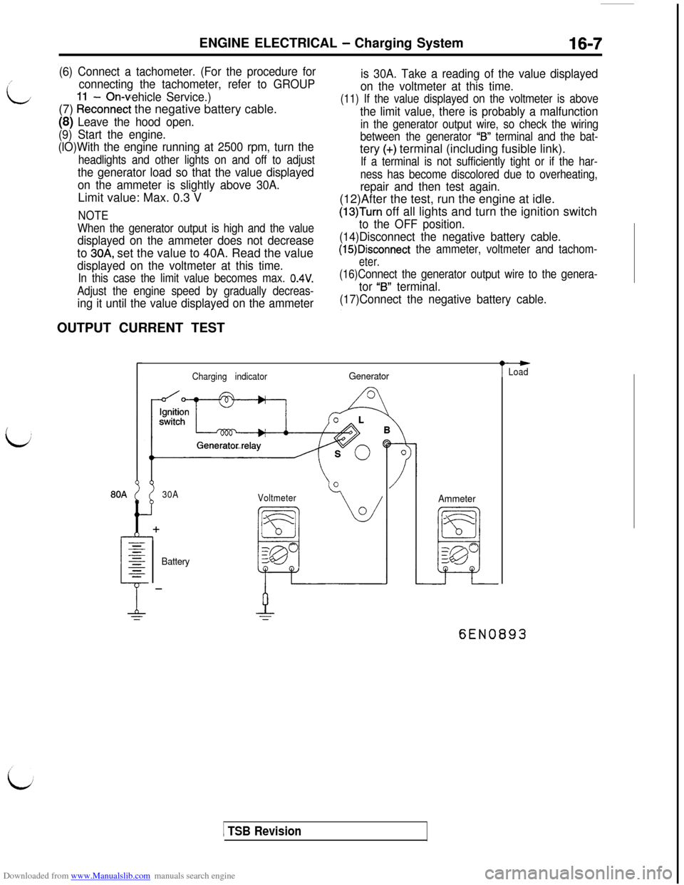
(6) Connect a tachometer. (For the procedure for
connecting the tachometer, refer to GROUP
- On-vehicle Service.)(7)
kkconnect the negative battery cable.
(8) Leave the hood open.
(9) Start the engine.
(lO)With the engine running at 2500 rpm, turn the
headlights and other lights on and off to adjust
the generator load so that the value displayed
on the ammeter is slightly above 30A.Limit value: Max. 0.3 V
NOTE
When the generator output is high and the value
displayed on the ammeter does not decreaseto
30A, set the value to 40A. Read the value
displayed on the voltmeter at this time.
In this case the limit value becomes max. 0.4V.
Adjust the engine speed by gradually decreas-
ing it until the value displayed on the ammeterOUTPUT CURRENT TEST
is 30A. Take a reading of the value displayed
on the voltmeter at this time.
(11) If the value displayed on the voltmeter is above
the limit value, there is probably a malfunction
in the generator output wire, so check the wiring
between the generator
“IS” terminal and the bat-tery
(+) terminal (including fusible link).
If a terminal is not sufficiently tight or if the har-
ness has become discolored due to overheating,
repair and then test again.(12)After the test, run the engine at idle.
(13)Turn off all lights and turn the ignition switch
to the OFF position.
(14)Disconnect the negative battery cable.
(15)Disconnect the ammeter, voltmeter and tachom-
eter.
(16)Connect the generator output wire to the genera-
tor “B” terminal.
(17)Connect the negative battery cable.
Charging indicatorGenerator
30A
Voltmeter
BatteryAmmeter
t
-Load
6EN0893
1 TSB Revision
Page 454 of 738
Downloaded from www.Manualslib.com manuals search engine 16-8ENGINE ELECTRICAL - Charging System
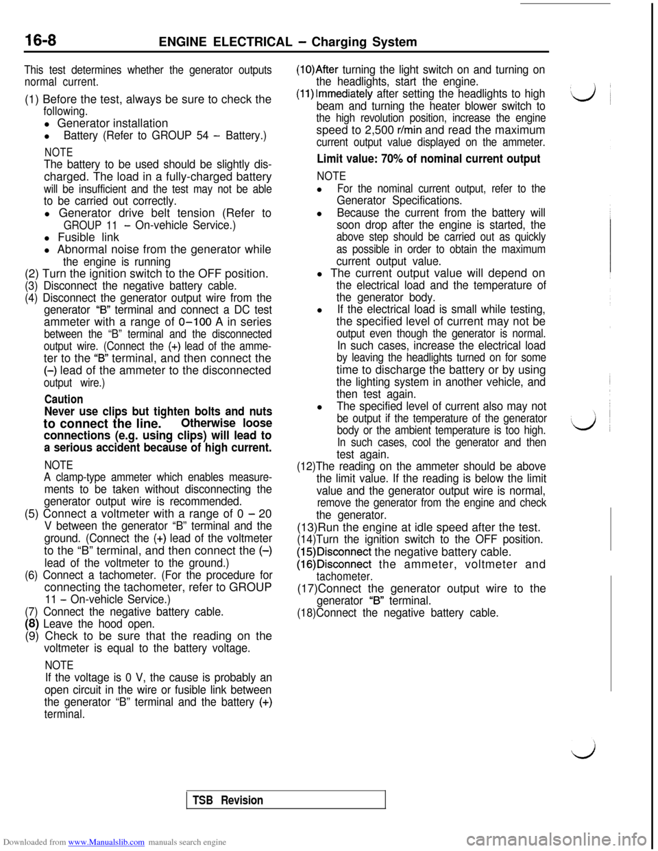
This test determines whether the generator outputs
normal current.(1) Before the test, always be sure to check the
following.l Generator installation
l
Battery (Refer to GROUP 54 - Battery.)
NOTE
The battery to be used should be slightly dis-charged. The load in a fully-charged battery
will be insufficient and the test may not be able
to be carried out correctly.l Generator drive belt tension (Refer to
GROUP 11- On-vehicle Service.)l Fusible link
l Abnormal noise from the generator while
the engine is running(2) Turn the ignition switch to the OFF position.
(3) Disconnect the negative battery cable.
(4) Disconnect the generator output wire from the
generator
“B” terminal and connect a DC testammeter with a range of O-100 A in series
between the “B” terminal and the disconnected
output wire. (Connect the
(+) lead of the amme-ter to the
“B” terminal, and then connect the(-) lead of the ammeter to the disconnected
output wire.)
Caution
Never use clips but tighten bolts and nutsto connect the line.
Otherwise loose
connections (e.g. using clips) will lead to
a serious accident because of high current.
NOTE
A clamp-type ammeter which enables measure-
ments to be taken without disconnecting the
generator output wire is recommended.(5) Connect a voltmeter with a range of 0
- 20
V between the generator “B” terminal and the
ground. (Connect the
(+) lead of the voltmeterto the “B” terminal, and then connect the (-)
lead of the voltmeter to the ground.)
(6) Connect a tachometer. (For the procedure forconnecting the tachometer, refer to GROUP
11 - On-vehicle Service.)
(7) Connect the negative battery cable.
(8) Leave the hood open.(9) Check to be sure that the reading on the
voltmeter is equal to the battery voltage.
NOTE
If the voltage is 0 V, the cause is probably an
open circuit in the wire or fusible link between
the generator “B” terminal and the battery
(+)
terminal.
(1O)After turning the light switch on and turning on
the headlights, start the engine.
(1l)lmmediately after setting the headlights to high
beam and turning the heater blower switch to
the high revolution position, increase the enginespeed to 2,500
r/min and read the maximum
current output value displayed on the ammeter.
Limit value: 70% of nominal current output
NOTEl
For the nominal current output, refer to the
Generator Specifications.l
Because the current from the battery will
soon drop after the engine is started, the
above step should be carried out as quickly
as possible in order to obtain the maximum
current output value.l The current output value will depend on
the electrical load and the temperature of
the generator body.l
If the electrical load is small while testing,the specified level of current may not be
output even though the generator is normal.
In such cases, increase the electrical load
by leaving the headlights turned on for sometime to discharge the battery or by using
the lighting system in another vehicle, and
then test again.l
The specified level of current also may not
be output if the temperature of the generator
body or the ambient temperature is too high.
In such cases, cool the generator and then
test again.
(12)The reading on the ammeter should be above
the limit value. If the reading is below the limit
value and the generator output wire is normal,
remove the generator from the engine and check
the generator.(13)Run the engine at idle speed after the test.
(14)Turn the ignition switch to the OFF position.
(15)Disconnect the negative battery cable.
(16)Disconnect the ammeter, voltmeter and
tachometer.(17)Connect the generator output wire to the
generator “B” terminal.
(18)Connect the negative battery cable.
TSB Revision
Page 457 of 738
Downloaded from www.Manualslib.com manuals search engine ENGINE ELECTRICAL - Charging System16-11
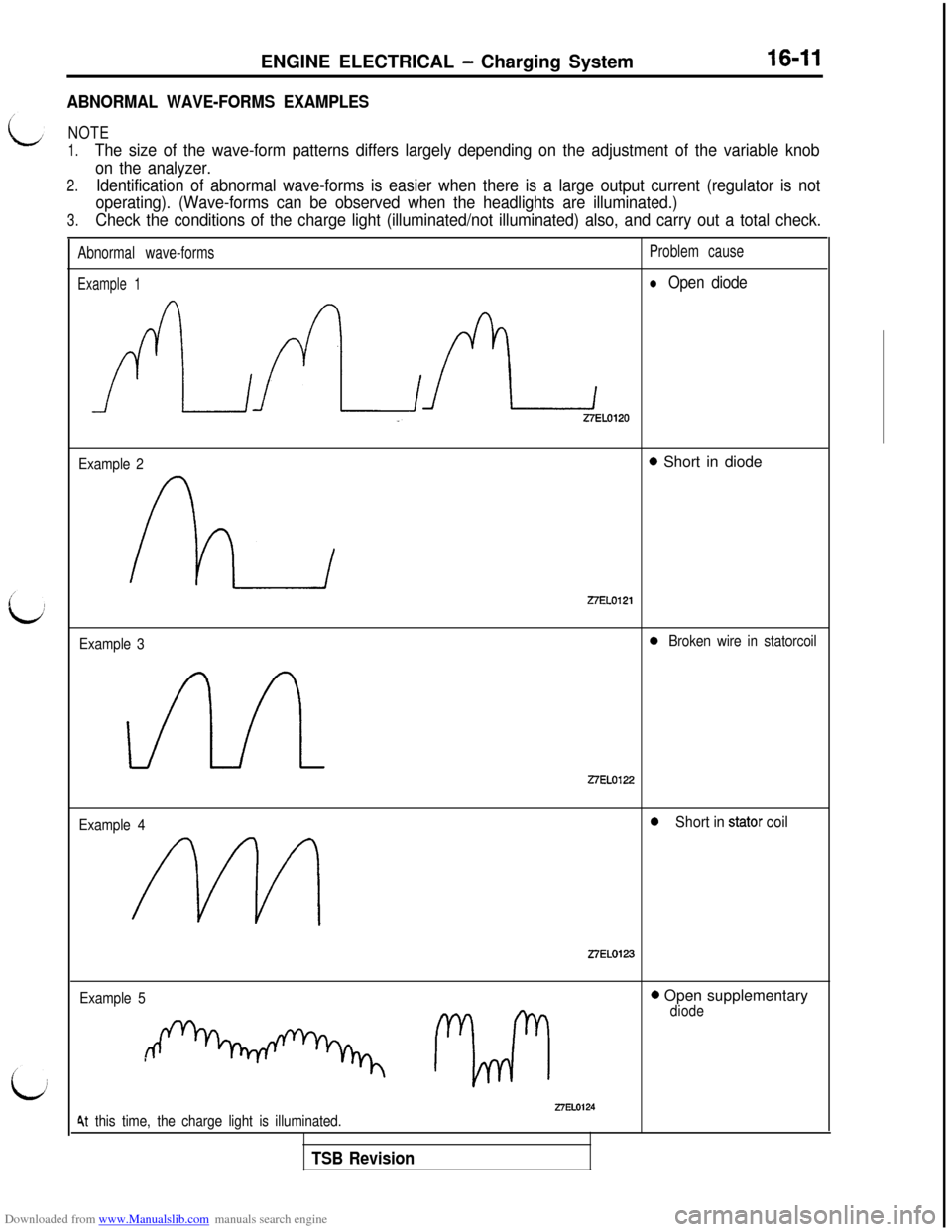
ABNORMAL WAVE-FORMS EXAMPLES
NOTE
1.The size of the wave-form patterns differs largely depending on the adjustment of the variable knob
on the analyzer.
2.Identification of abnormal wave-forms is easier when there is a large output current (regulator is not
operating). (Wave-forms can be observed when the headlights are illuminated.)
3.Check the conditions of the charge light (illuminated/not illuminated) also, and carry out a total check.
Abnormal wave-formsProblem cause
Example 1l Open diode
AALZELOlZO
Example 20 Short in diodeZ7EL0121
Example 30Broken wire in statorcoil
27EL0122
Example 40Short in stator coil
Z7EL0123
Example 5
1 r2rrirl
0 Open supplementarydiode
27EL01244t this time, the charge light is illuminated.
TSB Revision