headlight MITSUBISHI 3000GT 1992 2.G Service Manual
[x] Cancel search | Manufacturer: MITSUBISHI, Model Year: 1992, Model line: 3000GT, Model: MITSUBISHI 3000GT 1992 2.GPages: 738, PDF Size: 35.06 MB
Page 549 of 738
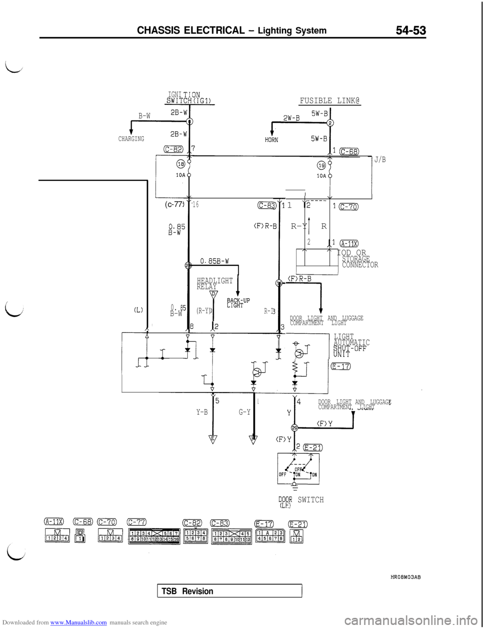
Downloaded from www.Manualslib.com manuals search engine CHASSIS ELECTRICAL - Lighting System54-53
IGNISWIT
B-W2B-
CHARGING
(L)
r_c
A-
I(c-77:
0. 8!B-W
,
FUSIBLE LINK@
16(c-8c
(F)R-
0.85B-W
HEADLIGHT
RELAY
D
Y
&m&UP
(R-Y)R-I
5
I
G-Y Y-B
10AI
r!
J/B
\/I1
\2---_
1mR-Y R
I
2,.l (A-11x)I\A IOD ORSTORAGE
CONNECTOR
(F)R-B
1DOOR LIGHT AND LUGGAGE
COMPARTMENT LIGHT
-is---l
LIGHT
AUTOMATIC
Kw°FF
DOOR LIGHT
AND LUGGAGE
COMPARTMENT LIGHT
--
s!fip SWITCHHROBMOSAB
TSB Revision
Page 551 of 738
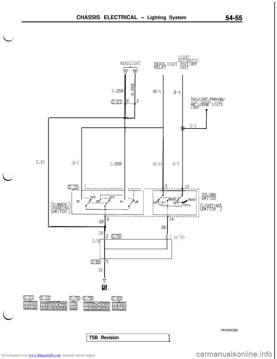
Downloaded from www.Manualslib.com manuals search engine CHASSIS ELECTRICAL - Lighting System54-55
LIGHT
AUTOMATIC
IGHT s/Y;-OFFHEADLIGHTHE!REL\DL,AY
1.25RG-Y
G-Y
TAILLIGHT,PARKING/
SIDE MARKER LIGHT
;yeHkICENSE PLATE
JG-Y
10
t
0.85(R-Y
(c-10)1
1.25R(R-Y
-----__
r
)2---------------
~:JqzT
-----_
-_
ILO
OP
2Bx.3 (c-76)
J/B A,\ 7 (c-78)
(c-82) "5
2B
HROBM03BB
TSB Revision1
Page 556 of 738
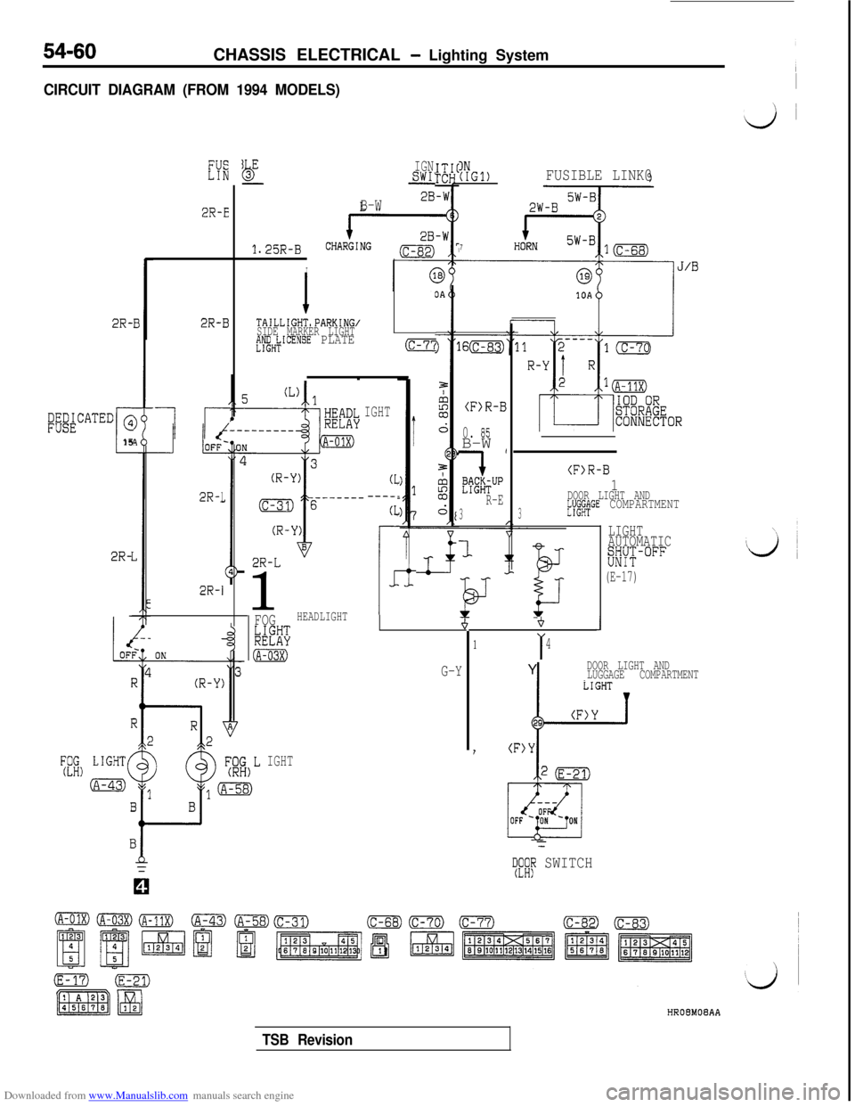
Downloaded from www.Manualslib.com manuals search engine 54-60CHASSIS ELECTRICAL - Lighting System
CIRCUIT DIAGRAM (FROM 1994 MODELS)I
2R-E
LEb-
1.25R-B
I
IGNSWI’IN(IGl)FUSIBLE LINK@
7
B-W
2R-B
I I
lr-
TAILLIGHT,PARKING/
SIDE MARKER LIGHT
#eH;ICENSE PLATE
2R-I
(c-7’i
(F>R-B
0. 05B-W (
'7
E%~TUPR-E
3
1
;ig&CATED @
c15
IGHT
2R-1
(F>R-B
1DOOR LIGHT AND
3E'I'UX&GE COMPARTMENT
2R-L1
(L----.
(L
r
1
LIGHT
AUTOMATIC
EK°FF
(E-17)
2R-
i
G-Y
2R-1
FOGHEADLIGHT
kB%
(A-03X)
+J
1I4Y
DOOR LIGHT AND
LUGGAGE COMPARTMENT
I(F>Y
vii L1GHT(A-43)
IGHT
=
TF;fi SWITCHHROBMOBAA
TSB Revision
Page 558 of 738
Downloaded from www.Manualslib.com manuals search engine 54-62CHASSIS ELECTRICAL - Lighting System
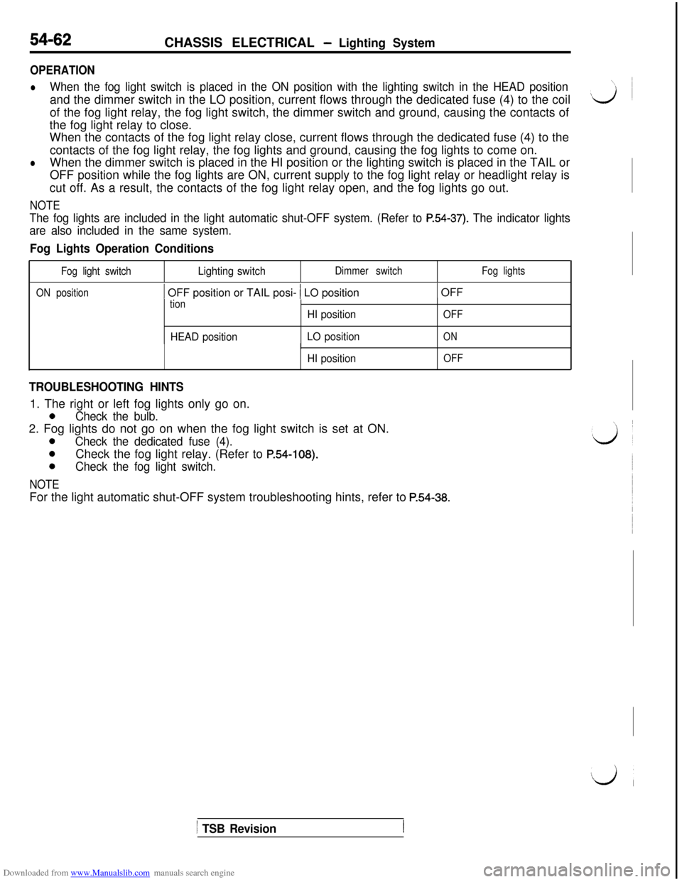
OPERATION
lWhen the fog light switch is placed in the ON position with the lighting switch in the HEAD positionand the dimmer switch in the LO position, current flows through the dedicated fuse (4) to the coil
of the fog light relay, the fog light switch, the dimmer switch and ground, causing the contacts of
the fog light relay to close.
When the contacts of the fog light relay close, current flows through the dedicated fuse (4) to the
contacts of the fog light relay, the fog lights and ground, causing the fog lights to come on.
lWhen the dimmer switch is placed in the HI position or the lighting switch is placed in the TAIL or
OFF position while the fog lights are ON, current supply to the fog light relay or headlight relay is
cut off. As a result, the contacts of the fog light relay open, and the fog lights go out.
NOTE
The fog lights are included in the light automatic shut-OFF system. (Refer to P.54-37). The indicator lights
are also included in the same system.
Fog Lights Operation Conditions
Fog light switchLighting switchDimmer switchFog lights
ON position
1 OFF position or TAIL posi- 1 LO position1 OFF
tion
HEAD positionHI position
LO position
OFF
ON
HI position
I
OFF
TROUBLESHOOTING HINTS1. The right or left fog lights only go on.
0Check the bulb.2. Fog lights do not go on when the fog light switch is set at ON.
0Check the dedicated fuse (4).
0Check the fog light relay. (Refer to P.54-108).
0Check the fog light switch.
NOTEFor the light automatic shut-OFF system troubleshooting hints, refer to
P.54-38.
1 TSB Revision
Page 559 of 738
Downloaded from www.Manualslib.com manuals search engine CHASSIS ELECTRICAL - Lighting System
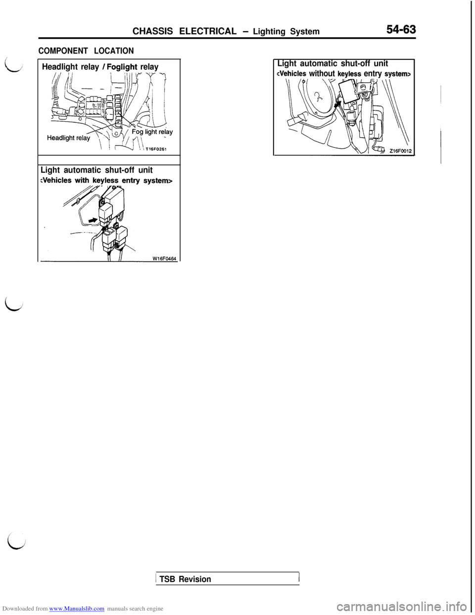
COMPONENT LOCATION
54-63
Headlight relay / Foglight relay
Light automatic shut-off unitLight automatic shut-off unit
1 TSB Revision
Page 562 of 738
Downloaded from www.Manualslib.com manuals search engine 54-66CHASSIS ELECTRICAL - Lighting System
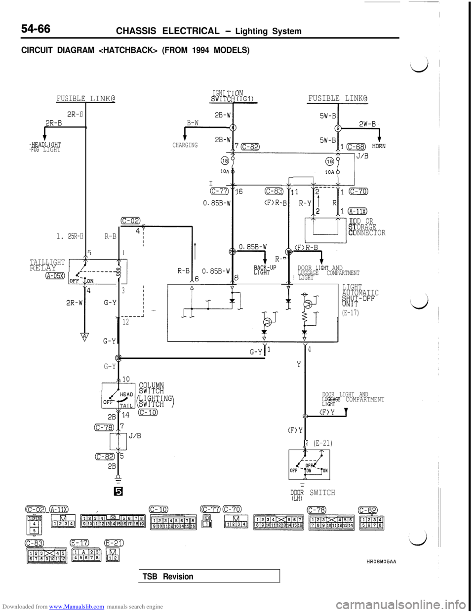
CIRCUIT DIAGRAM
FUSIBL
2R-1
2R-B
.HEADLIGHT.FOG LIGHT
#E
3
5
3
EI\-x-
1. 25R-1
TAILLIGHTRELAY ,r
LINK@
R-B
j2T
DOOR LIGHT AND.--__--LUGGAGE COMPARTMENT1 LIGHT
LIGHT
AUTOMATICKK-"""
-(E-17)
1
I
3
_----12
0.85B-W
1 R-
K#TUP1
(F>R-B
i-
G-Y ‘I4
&r1
G-Y
IDOOR LIGHT AND~JJ$C&GE COMPARTMENT29
(F>Y 'I
(F>Y
,,2 (E-21)
IGNISWIT
2B-B-W
cCHARGING
6I10
(c-7'i
O.S5B-
IN(IGl)FUSIBLE LINK@
07:;; SWITCH
cFE0 (A-11X)(c-02)(c-10)(c-68)cm~07)HROEMOBAA
16(c-8:!
(F>R-
----121mR-Y
1 R
t
210
IOD ORSTORAGE
CONNECTOR
TSB Revision
Page 564 of 738
Downloaded from www.Manualslib.com manuals search engine 54-68CHASSIS ELECTRICAL - Lighting System
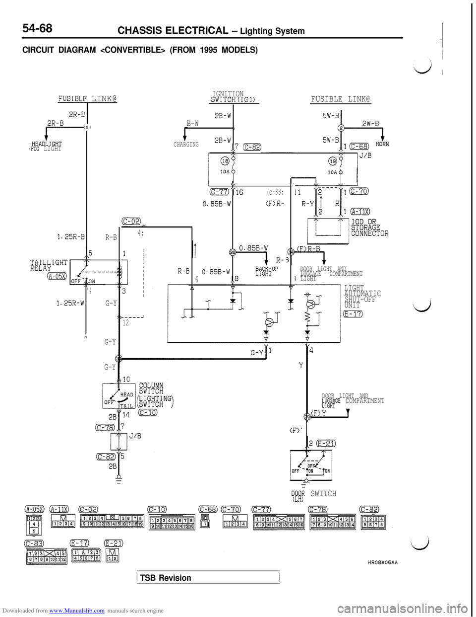
CIRCUIT DIAGRAM
FUSIBLE:LINK@
2R-B
f=-.HEADLIGHT.FOG LIGHT
5/
1.25R-B
R-B
5
'4
1.25R-W
G-Y
AG-Y
6G-Y
IGNITIONSWITCH(IG1)
I2B-WB-W6
CHARGING2B-W,,7 (c-82)rm
q----J12
FUSIBLE LINK@
0
(c-02),,
4:
0
6
I\/
O“16(c-83:
.85B-W(F>R-
@0.85B-W
R-
.85B-W,8E%ffTUP
10A
IP II
(F>R-B
DOOR LIGHT AND
LUGGAGE COMPARTMENT
3 LIGHT
LIGHT
AUTOMATIC
SHUT-OFF
UNIT
(E-17)
(F>'
DOOR LIGHT ANDkY;k+GE COMPARTMENT
(F>Y 7
it
yE[F SWITCH
1 TSB Revision
Page 566 of 738
Downloaded from www.Manualslib.com manuals search engine 54-70CHASSIS ELECTRICAL - Lighting System
OPERATION
0When the lighting switch is placed in the TAILor HEAD position, current flows through the
coil of the tail light relay to the lighting switchand ground, causing the contacts of the tail
light relay to close.
Then current flows through the contacts of thetail light relay to the dedicated fuse
(2) the
individual lights and ground, causing the tail
lights, parking/side marker lights and licenseplate lights to go ON.
lIf the driver’s door is opened after the ignition
switch is turned to “OFF” or the ignition switchis turned to “OFF” after the driver’s door is
opened when the tail lights are lit, the current
which flows to the coil side of the tail light relaywill be cut off by the light automatic shut-off
unit opening the contact point, and the tail light
relay will be turned “OFF’ to automatically shut
off the tail lights, parking and front side marker
lights and license plate light.
lTo turn on the tail lights, parking and front side
marker lights and license plate light again after
they are automatically shut off, turn the lightingswitch to “OFF” once and to “HEAD” again,
or turn the ignition switch to “ACC” or “ON”,
and the automatic shut-OFF will be cancelled
and the current will flow from the light automaticshut-OFF unit to the coil side of the tail light
relay to close the contact point. Thus, the taillight relay will be turned “ON” to turn on the
tail lights, parking and front marker lights and
license plate light.
NOTE
When the lighting switch is at the “HEAD” position,
the light automatic shut-OFF system will be also
activated for the headlights. (Refer to P.54-37.) The
same system will also be activated for the illumina-
tion lights, etc.
TROUBLESHOOTING HINTS1. All lights don’t illuminate.
(1) The headlights don’t illuminate, either.l Check the fusible link (3).
(2) The headlights illuminate.l Check the tail light relay. (Refer to
P.54-108.)l Check the dedicated fuse (2).
l Check the lighting switch. (Refer to
P.54-113.)l Check the light automatic shut-OFF
unit. (Refer to
P.54-108.)2. Some light does not come on.
l Check the bulb.
l Check the grounding circuit.
3. Some light is not automatically shut off.
lCheck the driver’s side door switch.
(Refer to GROUP 42- Door Assembly.)l Check the automatic shut-OFF unit.
(Refer to
P.54-108.)
1 TSB Revision
Page 577 of 738
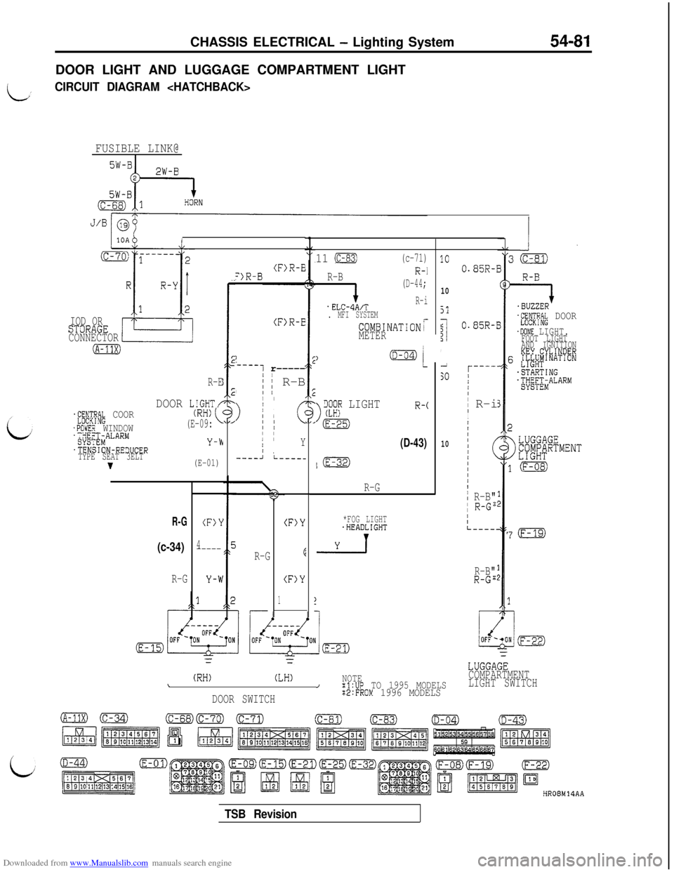
Downloaded from www.Manualslib.com manuals search engine CHASSIS ELECTRICAL - Lighting System54-81DOOR LIGHT AND LUGGAGE COMPARTMENT LIGHT
LCIRCUIT DIAGRAM
FUSIBLE LINK@I
I
IOD ORSTaRAGE
CONNECTOR
(A-11X)
R-E
DOOR LIGHT/.f;;$yik COOR
.POWER WINDOW';;gX$MALARM
.TENSION-RE3UCER
TYPE SEAT 3ELT
v
(RH)(E-09:
Y-b
(E-01)
R-G
(c-34)
R-G
(F)Y
4-----
(F>R-E=)R-B
(F>R-E
)
-----1 r-----/
,; ~ R-BII /
>
I/ II I1; cII II IIY/ ,----Ji-----
R-G
(F)Y
E
(F)Y
1
11 (c-83)(c-71)
R-B
i
(D-44;
.ELCdA/TR-i
. MFI SYSTEM
COMBINATIONrMETER
)
>
iX;? LIGHTR-c
m
(D-43)
l(E-32)
R-G
*FOG LIGHT.HEADLIGHT
-2-l
1C
10
51
$I1',1
SO
10
(RH)(LH)NOTE\/:l:UP TO 1995 MODELS
DOOR SWITCH%2:FROM 1996 MODELS
0.85R-1
0.85R-I
r----'/I/II
R-iI
I
/IIIII/(III/I
i R-B"I R-G":
/IL----.
R-B"R-G";
=I.BUZZER'L"RN;RP.k DOOR
.DOME LIGHT.FOOT LIGHT
AND IGNITION
KEY.CYLINDER6 &L#'NAT'ON
-STARTING.;yE;;iALARMj
7(F-19)
LUGGAGE
COMPARTMENT
LIGHT SWITCH
HR08M14AA
TSB Revision
Page 578 of 738
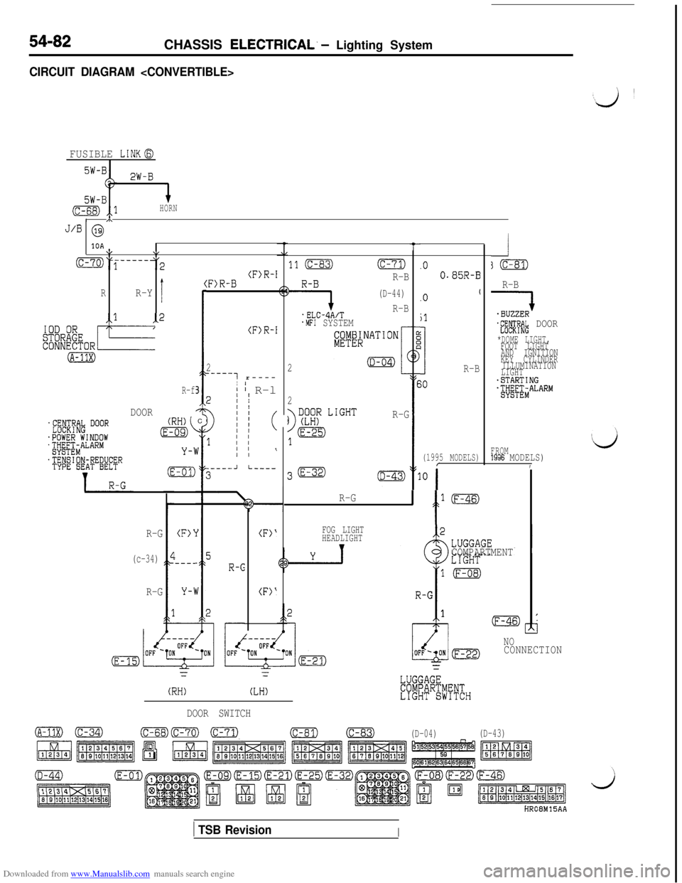
Downloaded from www.Manualslib.com manuals search engine 54-82CHASSIS ELECTRICAL. - Lighting System
CIRCUIT DIAGRAM
FUSIBLE LINKG
2W-B
5W-B(c-68) ,,lHORN/ m
J/B @
10A\I\,
(C-70)y-----3
I
(RR-Y
-1
(A-31X)
-2 I
R-f3
DOORC
R-B
QJ-fE#& DOOR
*DOME LIGHT,FOOT LIGHT
AND IGNITION
KEY CYLINDER
ILLUMINATION
LIGHT
-STARTINGjtjg&ALARM
t
11 (C-83)(c-71)
9
R-B
(D-44)
.ELC-4A/TR-B
.MFI SYSTEM
2
.O0.85R-B(F)R-I:F)R-B
(F)R-I
2
_----7 r----
I' I R-l2II
011 (
1 I/
I I\
.Ot
jl
3R-B
(1995 MODELS)
30
;0
2
R-G
FROM1996 MODELS),.----JI-----
R-G
' f
l(F-46)
R-G
(c-34)
R-G
FOG LIGHT
HEADLIGHT
vCOMPARTMENT
(F>‘
I---_
(F>‘
(F)'
NOCONNECTION
r=
(RH)(LH)
DOOR SWITCH
o(C-34)(c-68)Fml m(c-81)(c-83)
(D-04)(D-43)
HROBM15AA
1 TSB RevisionI