sensor MITSUBISHI 3000GT 1992 2.G Owner's Manual
[x] Cancel search | Manufacturer: MITSUBISHI, Model Year: 1992, Model line: 3000GT, Model: MITSUBISHI 3000GT 1992 2.GPages: 738, PDF Size: 35.06 MB
Page 54 of 738
Downloaded from www.Manualslib.com manuals search engine 52CONFIGURATION DIAGRAMS - Dash Panel
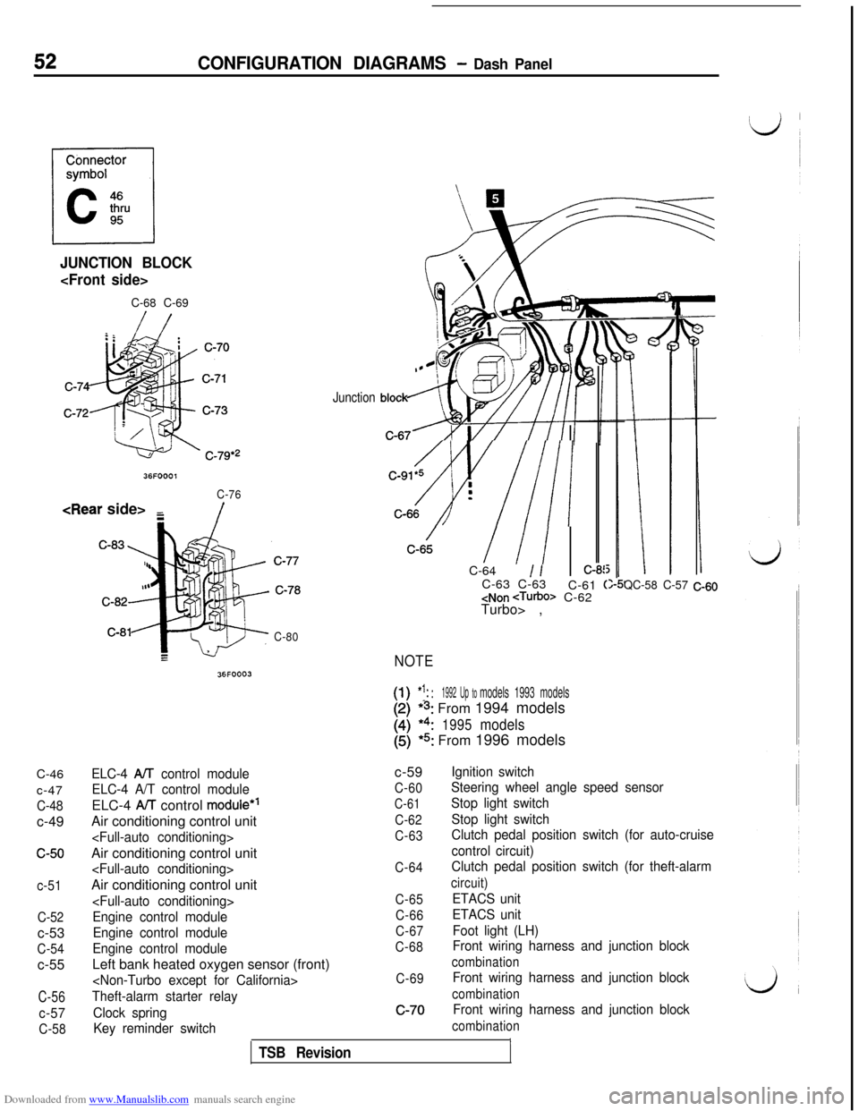
JUNCTION BLOCK
C-68 C-69C-46
c-47
C-48c-49
c-50
c-51
C-52c-53
C-54c-55
C-56
c-57
C-58
36FOOOl
C-76
/
C-80
36FOOO3
Junction
/C-91*5 i
Av///I :-C-64
1 /:-8!C-63 C-63
C-61
(
Turbo> ,
NOTE
[-I!1:: :1992 Up tomodels 1993 models
*s: From 1994 models
*4:1995models
(5)*5: From 1996 models
QC-58 C-57 C-60
ELC-4 AA control module
ELC-4 A/T control moduleELC-4
AiT control module*’Air conditioning control unit
Engine control module
Engine control module
Engine control moduleLeft bank heated oxygen sensor (front)
Theft-alarm starter relay
Clock spring
Key reminder switchc-59
C-60
C-61
C-62
C-63
C-64
C-65
C-66
C-67
C-68
C-69c-70
Ignition switch
Steering wheel angle speed sensor
Stop light switch
Stop light switch
Clutch pedal position switch (for auto-cruise
control circuit)
Clutch pedal position switch (for theft-alarm
circuit)
ETACS unit
ETACS unit
Foot light (LH)
Front wiring harness and junction block
combination
Front wiring harness and junction block
combination
Front wiring harness and junction block
combinationITSB Revision
Page 56 of 738
Downloaded from www.Manualslib.com manuals search engine 54CONFIGURATION DIAGRAMS - Instrument Panel and Floor Console
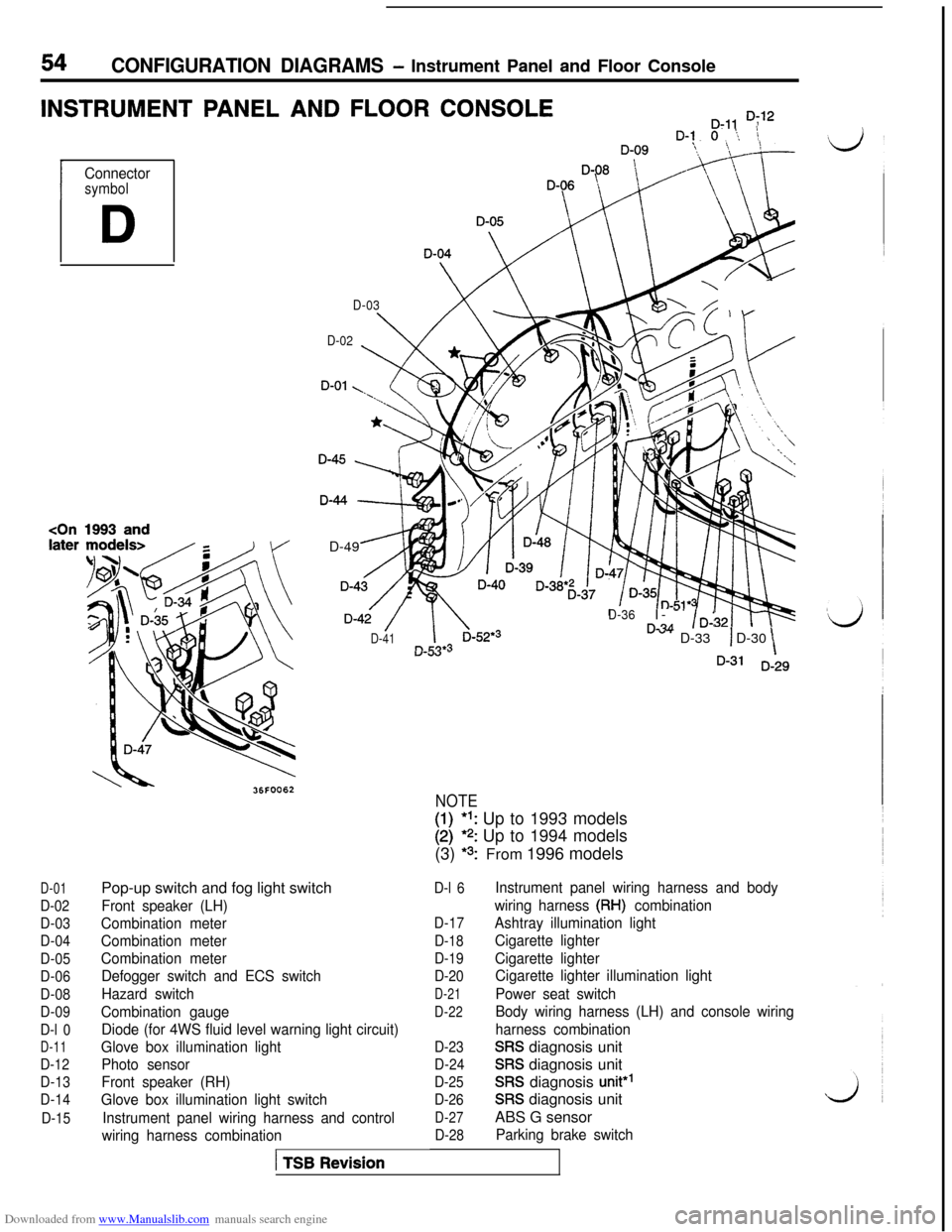
INSTRUMENT PANEL AND FLOOR CONSOLED-11 D;‘2D-1 0 ‘.,, \
I
Connectorsymbol
D
1993 and
D-03
D-Or ~~\\ Id&
D-02
4D-49 _
D-4i /
D-41
D-36I- -’rL?A/D-:” “- D-331 D-30“-c.w -\D-31 D-29
D-01
D-02
D-03
D-04
D-05
D-06
D-08
D-09
D-l 0
D-11
D-12
D-13
D-14
D-15Pop-up switch and fog light switch
Front speaker (LH)
Combination meter
Combination meter
Combination meter
Defogger switch and ECS switch
Hazard switch
Combination gauge
Diode (for 4WS fluid level warning light circuit)
Glove box illumination light
Photo sensor
Front speaker (RH)
Glove box illumination light switch
Instrument panel wiring harness and control
wiring harness combination
1 TSB Revision
NOTE
I:I*l: Up to 1993 models*? Up to 1994 models
(3)
*3:From 1996 models
D-l 6
D-17
D-18
D-19
D-20
D-21
D-22
D-23
D-24
D-25
D-26
D-27
D-28
Instrument panel wiring harness and body
wiring harness
(RH) combination
Ashtray illumination light
Cigarette lighter
Cigarette lighter
Cigarette lighter illumination light
Power seat switch
Body wiring harness (LH) and console wiring
harness combination
SRS diagnosis unit
SRS diagnosis unit
SRS diagnosis unit*’
SRS diagnosis unit
ABS G sensor
Parking brake switch
Page 58 of 738
Downloaded from www.Manualslib.com manuals search engine 56CONFIGURATION DIAGRAMS - Interior
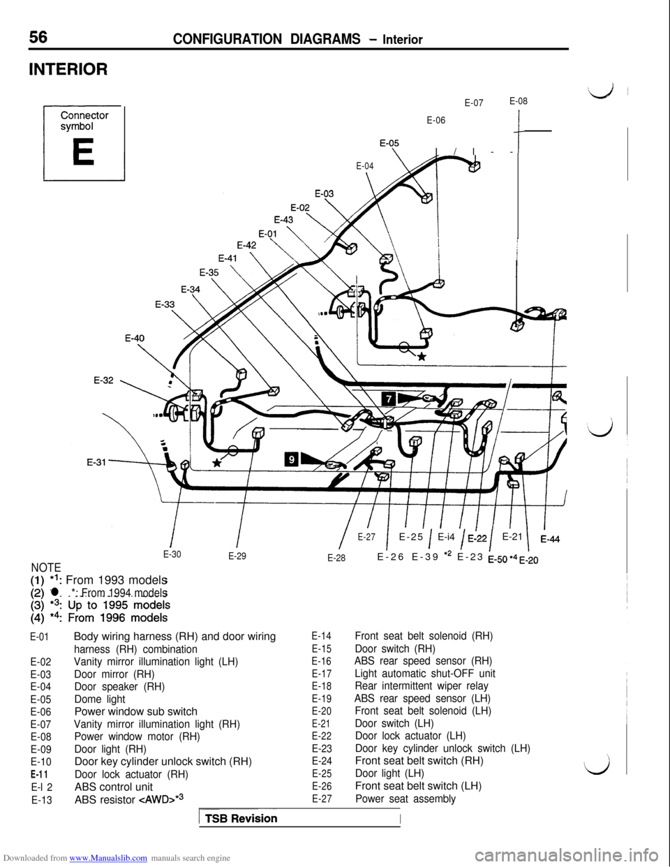
INTERIOR
E-07E-08
E-06
‘-OfI/l--c
E-04
\
II/E-27
E-30
1E-25 1 E-i4 / E:22/E-21 1
E-29
E-28
NOTEE-26 E-39
*2 E-23 EJJ, +4 ,520*I: From 1993 models
l *: From 1994 models
E-01
E-02
E-03
E-04
E-05
E-06
E-07
E-08
E-09
E-10
E-11
E-l 2
E-13Body wiring harness (RH) and door wiring
harness (RH) combination
Vanity mirror illumination light (LH)
Door mirror (RH)
Door speaker (RH)
Dome lightPower window sub switch
Vanity mirror illumination light (RH)
Power window motor (RH)
Door light (RH)Door key cylinder unlock switch (RH)
Door lock actuator (RH)ABS control unit
ABS resistor
-=zAWD>*~
E-14
E-15
E-16
E-17
E-18
E-19
E-20
E-21
E-22
E-23
E-24
E-25
E-26
E-27
Front seat belt solenoid (RH)
Door switch (RH)
ABS rear speed sensor (RH)
Light automatic shut-OFF unit
Rear intermittent wiper relay
ABS rear speed sensor (LH)
Front seat belt solenoid (LH)
Door switch (LH)
Door lock actuator (LH)
Door key cylinder unlock switch (LH)Front seat belt switch (RH)
Door light (LH)Front seat belt switch (LH)
Power seat assembly
ITSBionI
Page 59 of 738
Downloaded from www.Manualslib.com manuals search engine CONFIGURATION DIAGRAMS - InteriorE-45 E-46 E-47
E-48E-4g
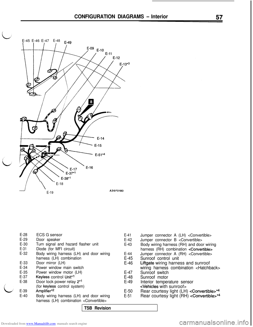
E-28
E-29
E-30
E-31
E-32
E-33
E-34
E-35
E-37
E-38
E-39
E-40
\
’ E-18
E-19ECS G sensor
Door speaker
Turn signal and hazard flasher unit
Diode (for MFI circuit)
Body wiring harness (LH) and door wiring
harness (LH) combination
Door mirror (LH)
Power window main switch
Power window motor (LH)
Keyless control Unit”’Door lock power relay 2*’
(for keyless control system)
Amplifier*2
Body wiring harness (LH) and door wiring
harness (LH) combination
E-41
E-42
E-43
E-44
E-45
E-46
E-47
E-48
E-49
E-50
E-51
Jumper connector A (LH)
Jumper connector B
harness (RH) combination
Jumper connector A (RH)
Sunroof control unit
Liftgate wiring harness and sunroof
wiring harness combination
Sunroof switch
Sunroof motor
Interior temperature sensor
Rear courtesy light (LH)
cConvertible>*4Rear courtesy light (RH)
cConvertible>*4
TSB Revision
Page 60 of 738
Downloaded from www.Manualslib.com manuals search engine 58CONFIGURATION DIAGRAMS - Luaaaae Compartment
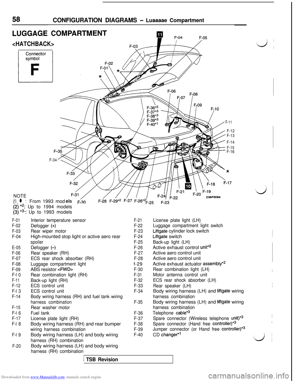
LUGGAGE COMPARTMENTpIl --.
F-11
F-12
F-13
F-14
F-15F-F-16
F-34
NOTE
(1) l ‘:From 1993 mod
[;I I’,: Up to 1994 models-_
: Up to 1993 models
F-01
F-02
F-03
F-04
E-05
F-06
F-07
F-08
F-09
F-l 0
F-11
F-12
F-l 3
F-14
F-15
F-l 6
F-17
F-l 8
F-l 9
F-20
Interior temperature sensor
Defogger
(+)
Rear wiper motorHigh-mounted stop light or active aero rear
spoiler
Defogger (-)
Rear speaker (RH)
ECS rear shock absorber (RH)
Luggage compartment lightABS resistor
Rear combination light (RH)
Back-up light (RH)
ECS control unit
ECS control unit
Body wiring harness (RH) and fuel tank wiring
harness combination
Rear washer motor
Fuel tank
License plate light (RH)Body wiring harness (RH) and rear bumper
wiring harness combinationBody wiring harness (LH) and body wiring
harness (RH) combinationBody wiring harness (LH) and body wiring
harness (RH) combination
F-21
F-22
F-23
F-24
F-25
F-26
F-27
F-28f-29
F-30
F-31
F-32
F-33
F-34
F-35
F-36
F-37
F-38
F-39
F-40
License plate light (LH)
Luggage compartment light switch
Liftgate cylinder lock switch
Liftgate switch
Back-up light (LH)Active exhaust control
unit*2Active aero control unit
Active aero control unit
Active exhaust actuator
assembly*2
Rear combination light (LH)
Motor antenna control unit
ECS rear shock absorber (LH)
Rear speaker (LH)Body wiring harness (LH) and
liftgate wiring
harness combinationBody wiring harness (LH) and
liftgate wiring
harness combination
Telephone
cable*3
Spare connector (Wireless telephone unity3
Spare connector (Hand free
controller)*3
Jumper connector (or Hand free controller)*3CD
changer*’
1 TSB Revision
I
‘id ~~
I
II~
I
LJ
Page 66 of 738
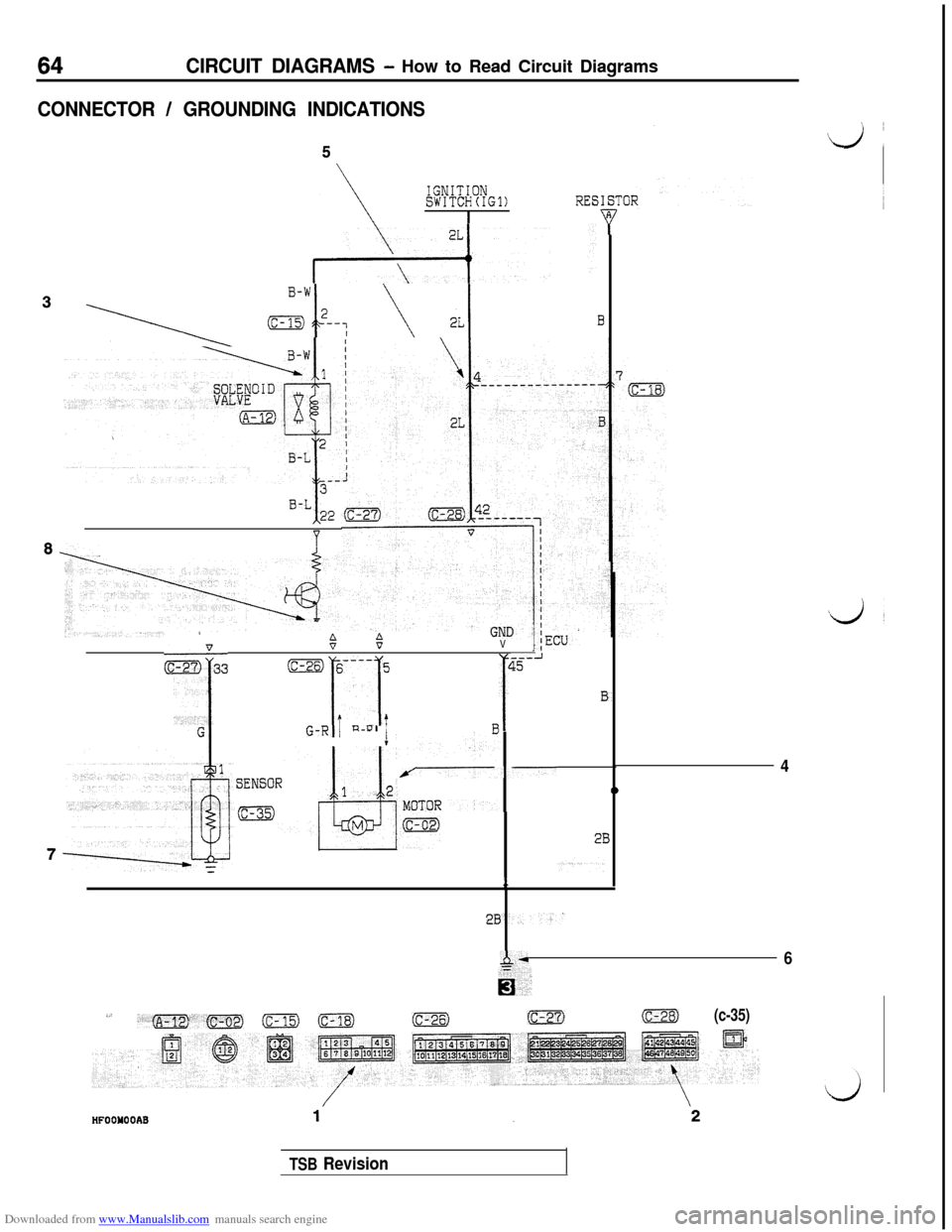
Downloaded from www.Manualslib.com manuals search engine CIRCUIT DIAGRAMS - How to Read Circuit Diagrams
CONNECTOR / GROUNDING INDICATIONS
IGNITIONSWITCH(IG1)RESI
IT
3 \ J?--: ‘- ^r;lI3
3B-LI22
8..e
:6
E&3
$5V
ic-26) 6---- 5
,I iI
45
1
---A
f3~
t -tGG-RI1 n-PI IAI
7-4
SENSOR0
q\v
213
1
A*6
ii,
,’,m,fC-021 ic-15) (c-18)fc-271(c-28f(c-35)
tr
TSB Revision
s1A7
Page 77 of 738
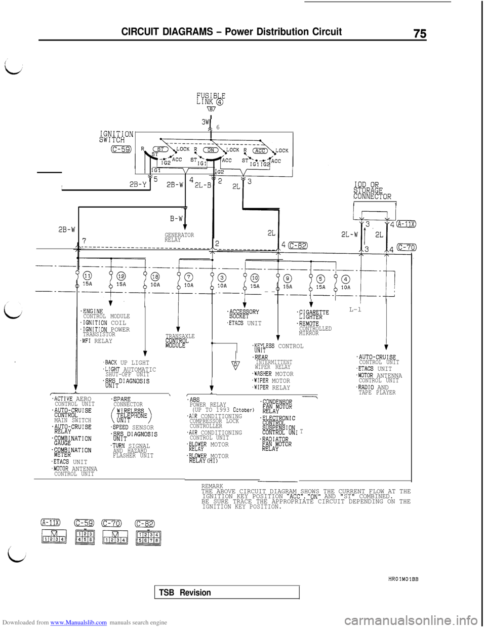
Downloaded from www.Manualslib.com manuals search engine CIRCUIT DIAGRAMS - Power Distribution Circuit75
IGNITION3y; 6
SWITCH
(c-59)
I
IGlVI
2B-YpL52B-W *2L-BIOD OR%ii&!OR
II
B-W
JGENERATOR7RELAY__-_--_-_____-___-_____________
2B-W
.ENGINECONTROL MODULE.IGNITION COIL.IGNITION POWERTRANSISTOR.MFI RELAYTRANSAXLE
ki8%EL
f
,BACK UP LIGHT.LIGHT AUTOMATICSHUT-OFF UNIT$$~TDIAGNOSIS
I$
'ABSPOWER RELAY(UP TO 1993 October).AIR CONDITIONINGCOMPRESSOR LOCK
CONTROLLER
.AIR CONDITIONINGCONTROL UNIT'&#R MOTOR
.BLOWER MOTORRELAYCHI)
.--_--
.&EE;qORY
.ETACS UNIT
+ L-l'#fiBi;'"
.REMOTECONTROLLED
MIRROR
+jjf$ESS CONTROLic
.REARINTERMITTENT
WIPER RELAY
.WASHER MOTOR.WIPER MOTOR.WIPER RELAY
.AUTO-CRUISECONTROL UNIT.ETACS UNIT.MOTOR ANTENNACONTROL UNIT.RADIO ANDTAPE PLAYER.ACTIVE AERO\
CONTROL UNIT.SPARECONNECTOR$@RC~UISE
MAIN SWITCH(jiifb%E)
~f$J&CRUISE.SPEED SENSOR
~'$@~NATION$/$TDIAGNOSIS
.&y&NATION.TURN SIGNALAND HAZARD
FLASHER UNIT
.ETACS UNIT.MOTOR ANTENNACONTROL UNIT
T
REMARKTHE ABOVE CIRCUIT DIAGRAM SHOWS THE CURRENT FLOW AT THE
IGNITION KEY POSITION "ACC","ON" AND "ST" COMBINED.
BE SURE TRACE THE APPROPRIATE CIRCUIT DEPENDING ON THE
IGNITION KEY POSITION.
HROlMOlBB
TSB Revision
Page 81 of 738
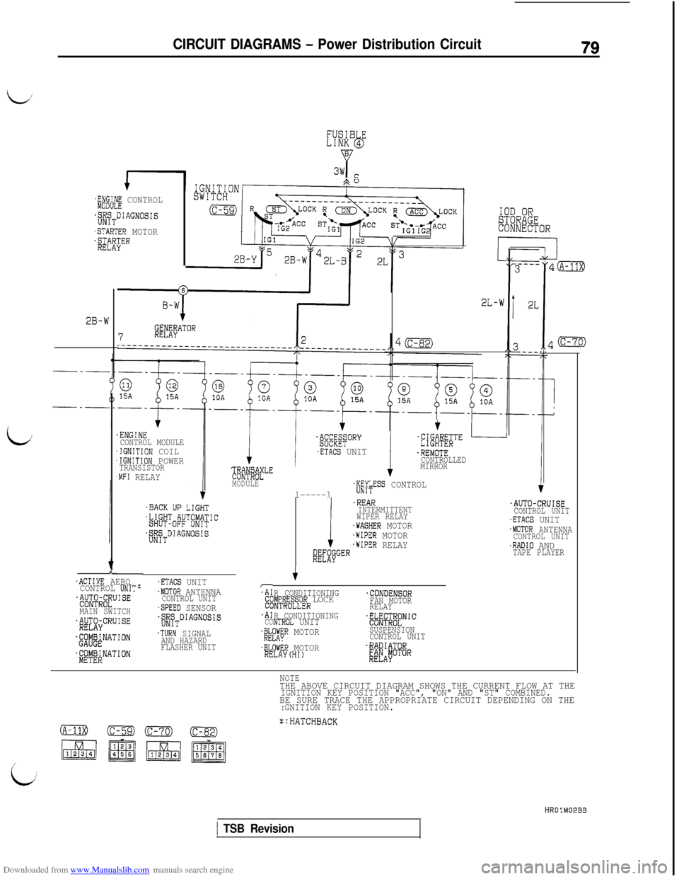
Downloaded from www.Manualslib.com manuals search engine CIRCUIT DIAGRAMS - Power Distribution Circuit79
FUSIB ELINK 4bB
Y3w c
'&# CONTROL
.;gTDIAGNO~~~
,STARTER MOTOR$$$;ER
IOD ORSTORAGECONNECTOR
4’
I
-J4a
*(c-70)
2L-w
2B-W
.ETACS UNIT
;I$@fLE
l-----l
IMODULE$i$ESS CONTROL
f$#;&TE
.REMOTECONTROLLED
MIRROR
.ENGINECONTROL MODULE,IGNITION COIL,IGNITION POWERTRANSISTOR,MFI RELAY
!
.REARINTERMITTENT
WIPER RELAY
.WASHER MOTOR.WIPER MOTOR.WIPER RELAY;gL"itGER
.AUTO-CRUISECONTROL UNIT.ETACS UNIT.MOTOR ANTENNACONTROL UNIT.RADIO ANDTAPE PLAYER
A.ACTIVE AERO
CONTROL UNIT:.#J$$;U'SE
MAIN SWITCHj&CRUISE
.ETACS UNIT.MOTOR ANTENNACONTROL UNIT.SPEED SENSOR.$WSTDIAGNOSI~
.TURN SIGNALAND HAZARD
FLASHER UNIT
TI
2.A1CC
R CONDITIONINGIMPRESSOR LOCK.CONDENSOR
INTROLLERFAN MOTOR
RELAY
R CONDITIONING
lNTROL UNITf~~~;~L"NIC
$kL"A"&R MOTORSUSPENSION
CONTROL UNIT
.BLOWER MOTOR.RADIATORRELAYCHI)[;FAyOTOR$&&NATION.~~~~RNATION
NOTETHE ABOVE CIRCUIT DIAGRAM SHOWS THE CURRENT FLOW AT THEIGNITION KEY POSITION "ACC", "ON" AND "ST" COMBINED.BE SURE TRACE THE APPROPRIATE CIRCUIT DEPENDING ON THEIGNITION KEY POSITION.
::HATCHBACK
HROlM02BB
1 TSB Revision
Page 85 of 738
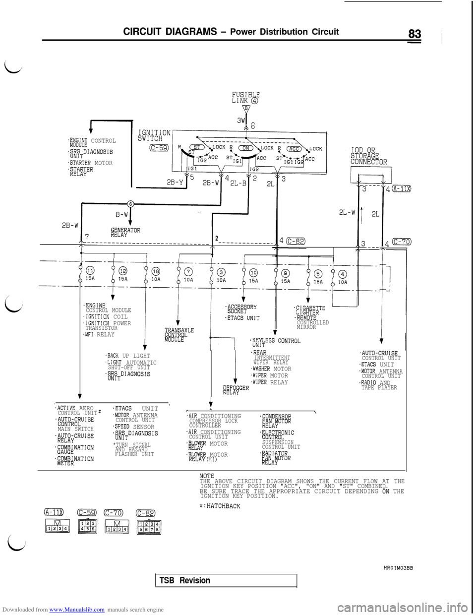
Downloaded from www.Manualslib.com manuals search engine CIRCUIT DIAGRAMS - Power Distribution Circuit
L,
FUSIB ELINK 4bB
P3w P
$$d! CONTROL
jj!JyTDIAGNOSIS
.STARTER MOTOR$$eEl?ER
2L-w
:
J
I
2B-b
7@#"TO"
2__-__--__-__-_--_--_--~~-~~-~-- -_-----__-_--_C\
1I/4,/---t-_
/
i/.ENGINECONTROL MODULE.IGNITION COIL.IGNITION POWERTRANSISTOR.MFI RELAY
.REMOTECONTROLLED
MIRROR
.AUTO-CRUISECONTROL UNIT.ETACS UNIT.MOTOR ANTENNACONTROL UNIT.RADIO ANDTAPE PLAYER
.BACK UP LIGHT.LIGHT AUTOMATICSHUT-OFF UNIT.;;~TDIAGNOSIS
i
.REARINTERMITTENT
WIPER RELAY
.WASHER MOTOR.WIPER MOTOR.WIPER RELAY@L"'$jGER
:ACTIVE AEROCONTROL UNIT~~~&~~U'SE
MAIN SWITCH$&CRUISE
.@j&NATION
$'~$!$NATION
:.ETACS UNIT '.MOTOR ANTENNACONTROL UNIT.SPEED SENSORjiyTDIAGNOSIS
*TURN SIGNALAND HAZARD
FLASHER UNITr
*
.AIR CONDITIONING\
COMPRESSOR LOCK.CONDENSOR
CONTROLLER;@AiOTOR
.AIR CONDITIONINGCONTROL UNIT.~@;~~NIC
.&A";R MOTORSUSPENSIONCONTROL UNIT
.BLOWER MOTOR.RADIATORRELAY(HI)&JAFOTOR
THE ABOVE CIRCUIT DIAGRAM SHOWS THE CURRENT FLOW AT THE
IGNITION KEY POSITION "ACC", "ON" AND "ST" COMBINED
BE SURE TRACE THE APPROPRIATE CIRCUIT DEPENDING ON THEIGNITION KEY POSITION.
X:HATCHBACK
HROlM03BB
TSB Revision
Page 88 of 738
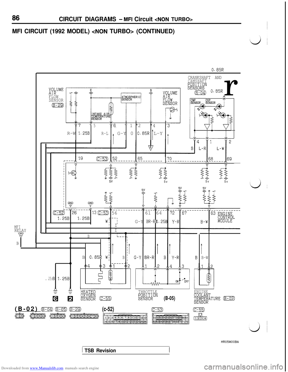
Downloaded from www.Manualslib.com manuals search engine 86CIRCUIT DIAGRAMS - MFI Circuit
MFI CIRCUIT (1992 MODEL)
MFIRELAYC
YB
0.85R
XW””FLOW
SENSOR
(8-29)
\/\k\/“7" 5“6" 1 "2"4
R-W 1.25BR-LG-Y 0 0.85R L-Y
I
CRANKSHAFT ANDCAMSHAFT
- Wan"(~-64) 0.85Rr
5v5v5v
5v
19r---IIvvII/IIIIIIIIfrF Y-/I/ GNDGND
(c-52) %6VL- ------Y130 5661 64
1.25B1.25Bw/--iG-Y BR-R1.258j I
' I
L-&r
L
+B
. 25:B 1.25B
III
iI
IIIIB
0.85R W/IB I10------i:,4253 $51ts;
THROTTLE!Xl;Xl;;ON(B-05)
I
B-W
1ENGINE
f[i&i/iTURE (8-02)(B-02)
mz) (B-05) (8-29)(c-52)ic-53)(c-55)HR05MOOBA
1 TSB Revision