MITSUBISHI 3000GT 1992 2.G Workshop Manual
Manufacturer: MITSUBISHI, Model Year: 1992, Model line: 3000GT, Model: MITSUBISHI 3000GT 1992 2.GPages: 738, PDF Size: 35.06 MB
Page 321 of 738
Downloaded from www.Manualslib.com manuals search engine CIRCUIT DIAGRAMS - Rear Wiper and Washer Circuit
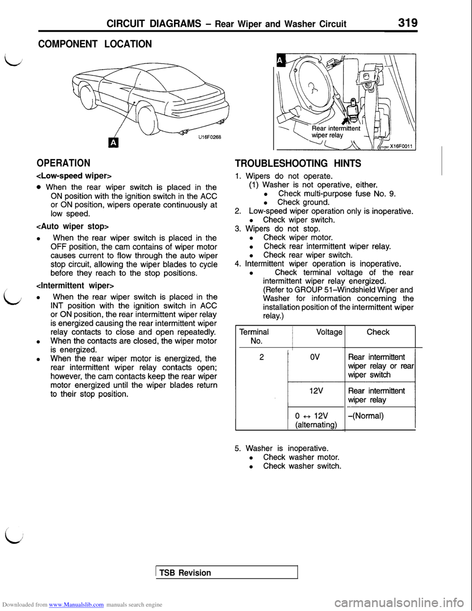
COMPONENT LOCATION
OPERATION
0 When the rear wiper switch is placed in the
ON position with the ignition switch in the ACC
or ON position, wipers operate continuously at
low speed.
When the rear wiper switch is placed in the
OFF position, the cam contains of wiper motor
causes current to flow through the auto wiper
stop circuit, allowing the wiper blades to cycle
before they reach to the stop positions.
i
When the rear wiper switch is placed in the
INT position with the ignition switch in ACC
or ON position, the rear intermittent wiper relay
is energized causing the rear intermittent wiper
relay contacts to close and open repeatedly.l
When the contacts are closed, the wiper motor
is energized.l
When the rear wiper motor is energized, the
rear intermittent wiper relay contacts open;
however, the cam contacts keep the rear wiper
motor energized until the wiper blades return
to their stop position.
TROUBLESHOOTING HINTS
1. Wipers do not operate.
(1) Washer is not operative, either.l
Check multi-purpose fuse No. 9.l
Check ground.
2.Low-speed wiper operation only is inoperative.l
Check wiper switch.
3. Wipers do not stop.l
Check wiper motor.l
Check rear intermittent wiper relay.l
Check rear wiper switch.
4. Intermittent wiper operation is inoperative.l
Check terminal voltage of the rear
intermittent wiper relay energized.
(Refer to GROUP 51-Windshield Wiper and
Washer for information concerning the
installation position of the intermittent wiper
relay.)
Terrr$al 1 Voltage
I
12v
0 3-b 12v
1 (alternating)
5. Washer is inoperative.l
Check washer motor.l
Check washer switch.
Check
Rear intermittent
1 TSB Revision
Page 322 of 738
Downloaded from www.Manualslib.com manuals search engine 320CIRCUIT DIAGRAMS - Remote Controlled Mirror Circuit
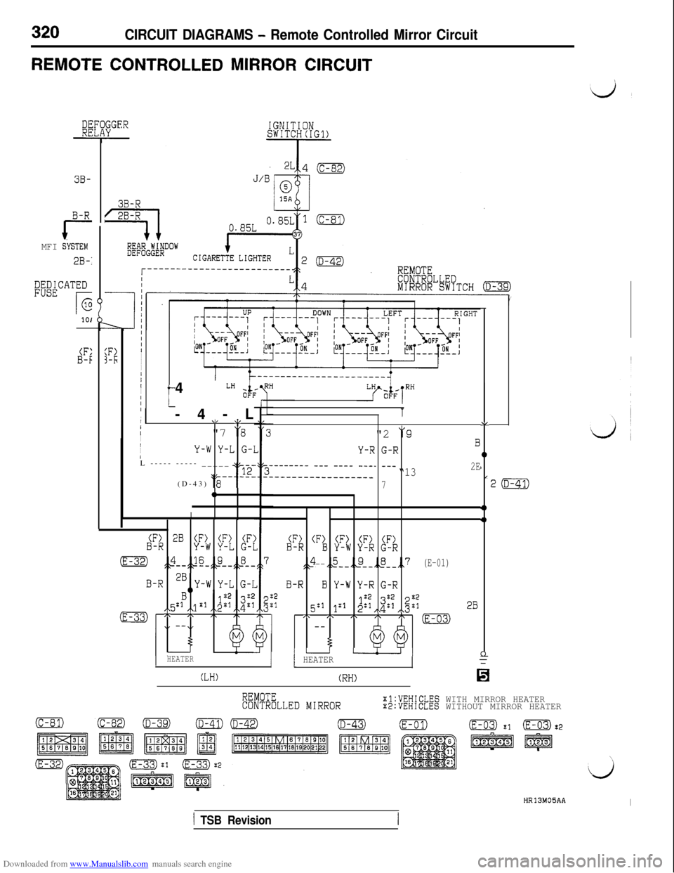
REMOTE CONTROLLED MIRROR CIRCUIT
3B-
B-R
rMFI SiSTEM
20-I
DEDICATEDFUSE
r(2
101
:F>3-I;
11
III
I
I
I/II
I
III,//II/
I
/4
LH
t21-4-L
d/ \,"7
"8
Y-W Y-L G-:L ----- ----- _____
“r12(D-43)
‘g------0
I
(F> 28 (F) (F> (F:B-RY-W Y-L G-I
(E-32) ,&-,p&&-
B-R 2B,,Y-W Y-L G-I
,:1B 1:'
(E-33) :\2--
HEATER
(LH)
\RH
1"2
j‘9
Y-R G-RB
-------- --- ---- ---_ ___“132E____----___--_-___7
(F) (F> (F> (F) (F)B-RB Y-W Y-R G-R
$3 ,,5--,_4-,,g-,,7--(E-01)
B-RB Y-W Y-R G-R:2:15:1 1x18;;$;I\ ,\g;2B/\ /\ I\ /\ I\ (E-03)--
5I- UI1 HEATER
(RH)
AL
0
1I
4)
4)
cl=
2(D-41)
REMOTECONTROLLED MIRRORXl:VEHICLES WITH MIRROR HEATER:2:VEHICLES WITHOUT MIRROR HEATER
HR13M05AAI
1 TSB Revision
Page 323 of 738
Downloaded from www.Manualslib.com manuals search engine CIRCUIT DIAGRAMS - Remote Controlled Mirror Circuit321 ~
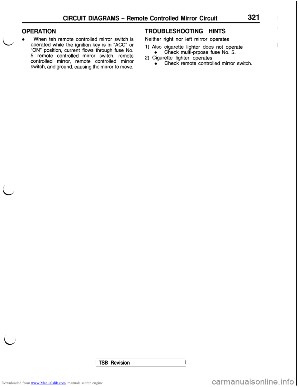
OPERATIONTROUBLESHOOTING HINTSI
Ll When teh remote controlled mirror switch isNeither right nor left mirror operates
operated while the ignition key is in “ACC” or
“ON” position, current flows through fuse No.1) Also cigarette lighter does not operateI
5 remote controlled mirror switch, remotel Check multi-prpose fuse No. 5.
controlled mirror, remote controlled mirror2) Cigarette lighter operates
switch, and ground, causing the mirror to move.l Check remote controlled mirror switch.
1 TSB RevisionI
Page 324 of 738
Downloaded from www.Manualslib.com manuals search engine 322Anti-lock Braking System (ABS)
CIRCUIT DIAGRAMS - Circuit
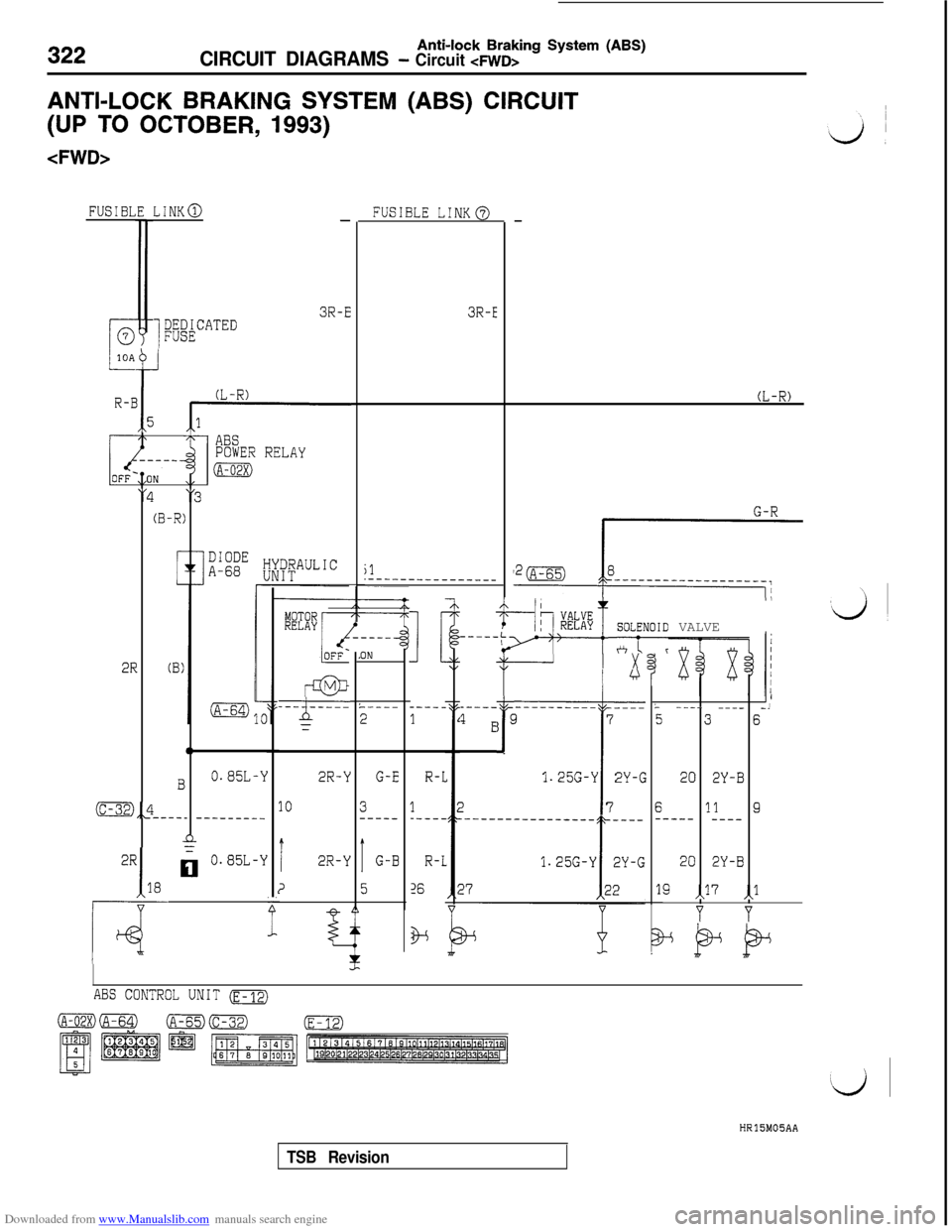
ANTI-LOCK BRAKING SYSTEM (ABS) CIRCUIT
(UP TO OCTOBER, 1993)
FUSIBLLINK@-FUSIBLE LINK@
3R-E3R-E
i&&CATED
R-E
b
i5
(L-R)
7ABSPOWER RELAY
IA-02X)
"4"3
(B-R)
2R
=z==
0
B0.85L-Y
m,Jl----_ --------_
n-
00.85L-Y
t
2R-Y
10
T2R-Y
2
G-R
jl.___-__________--
I !
----_
1
+--&";T ;fNOID VALVE1;
z
ft
I x
i
I-
E27
;I
1.25G-Y 2Y-G
7
IL ---- --__ -,
536
20 2Y-B
611 9----- ---_
----_
-----
' E
20 2Y-B
19 ,>7 ,,l
Y Y
.ON
L----
2
R-l
1-----
R-L
16
G-E
3-----
IG-B
5f2
f
ABS CONTROL UNIT (E-12)
HR15M05AA
TSB Revision
Page 325 of 738
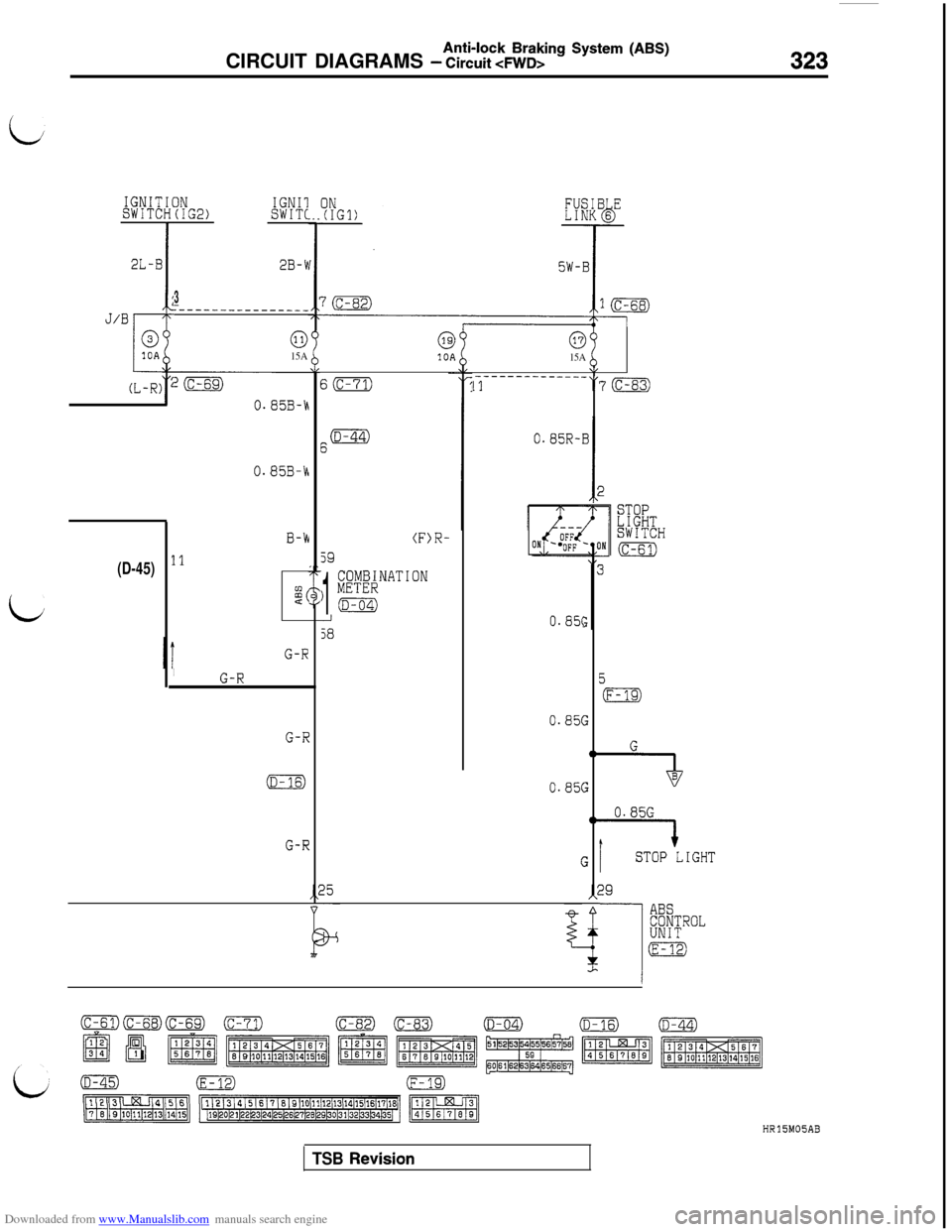
Downloaded from www.Manualslib.com manuals search engine Anti-lock Braking System (ABS)CIRCUIT DIAGRAMS - Circuit 4WD>323
i
L
IGNITSWITC
2L-B
J/B
(L-R)
(D-45)
INIGNII(IG2)SWITC
2B-1
3:----------------
015A
?(c-69)
0.85B-VI
0.85B-k
B-k
11
$2
IG-R
G-R
G-R
S(c-71)
6o
(F)R-
59
1
COMBINATION) METER
(D-04)-J
58
015A\/--------______13“7 (c-83)
0.85R-B
I2
0.8%
0.85(
0.85(
(
;
ac
;
tc
;A
i
STOPLIGHTSWITCH
(c-61)
5
(F-1S)
T7B
0.85G
STOP LIGHT29
ABSCONTROLUNIT
(E-12)
(D-45)(E-12)(F-19)
m/HR15M05AB
TSB Revision
Page 326 of 738
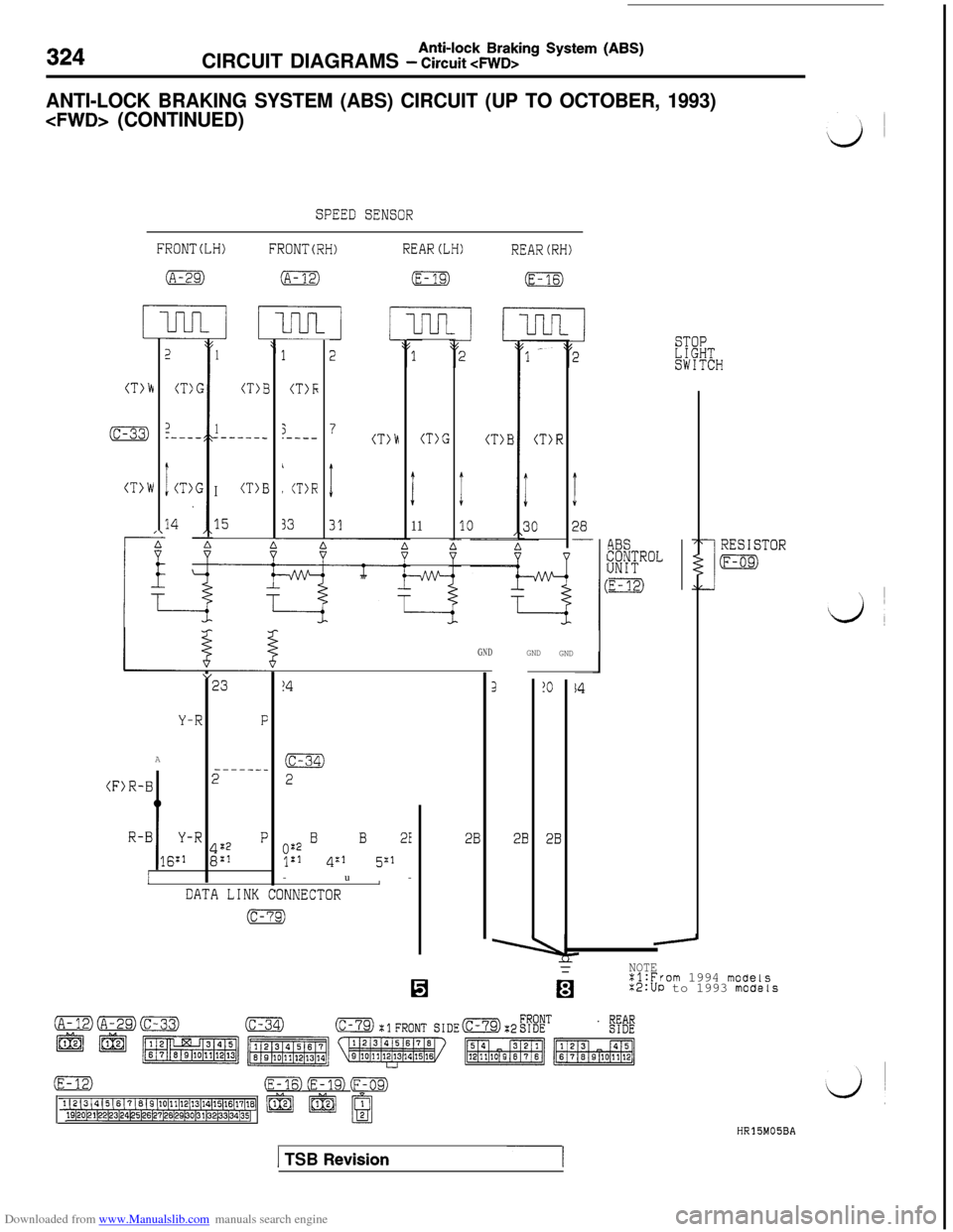
Downloaded from www.Manualslib.com manuals search engine 324CIRCUIT DIAGRAMS - Circuit cFWD>Anti-lock Braking System (ABS)
ANTI-LOCK BRAKING SYSTEM (ABS) CIRCUIT (UP TO OCTOBER, 1993)
SPEED SENSOR
FRONTCLH)FRONTCRH)REAR(LH)REAR(RH)
(A-29)(A-12)iE-19)(E-16)
(T>h
(c-33)
(T>W
2
CT:
3:---
:CT)
14
1
CT)1
1------.
ICT)1
15
1
(T>F;
3.----
,
, (T>R
33
(T)E
:
10
I
28-
TCH
(T)R(T)G
I
11
7(T)h
RESISTOR
(F-09)
4BS@UROL
m
GNDGND
GND
”23
Y-RFA
------_
.B2
,B
g::
P
I
3!O
2B2B2B
!4
(c-34)
2(F>R-
R--u-
y::
BB21
4:1 5:1
/IDATA LINK CONNECTOR
(c-79)
-NOTE:l:From 1994 moueis%2:UP to 1993 mocfels
(E-12)(E-16) (E-19) ~~
1(2~3j4(5(6(?~6(9(10(11~12/13~14(15(16(17118j m19/20~21~22~23~24~5~6~27/28/29po131~32~33~34~35] pf m B
HR15M05BA
1 TSB Revision-~-I
Page 327 of 738
Downloaded from www.Manualslib.com manuals search engine i
1 TSB Revision
Page 328 of 738
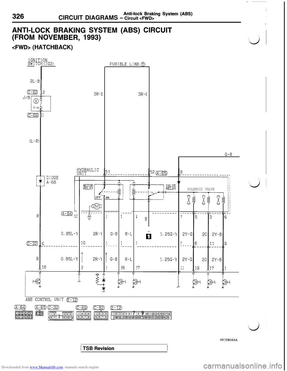
Downloaded from www.Manualslib.com manuals search engine 326CIRCUIT DIAGRAMS - Circuit cFWD>Anti-lock Braking System (ABS)
ANTI-LOCK BRAKING SYSTEM (ABS) CIRCUIT
(FROM NOVEMBER, 1993)
IGbSW1-
2L
(C-E
J/B(
L1
(C-E
(L-
Q ,,:-7
3OA
--LL
92
-R)
r-
IN(IG2)
I
DIODEA-68
FUSIBLE LINK@
3R-E3R-E!!---
----------- ---!I
SOLENOID VALVE
R
i
34
R
1
4
kkEBr/
_----
11 B
----------
R-L
1.----
01.25G-k2Y-G
7-----
R-L1.25G-Y2Y-G
16!722
/OFF‘
M
-4F.-- -----=ON
-----
2
2R-\IG-B
103--------------
i2R-kIG-B
25-
Y
1@mlC
o.a5~-k
-------z------
0.85w
a
ABS CONTROL UNIT (E-12)
5 16 / 7 / 8 / 9 j10~11/12~13~14~15~16117j1819~Ol21~22~3~24~25~26~27128129130plp8133~34~35~
HRlSMOGAA
1 TSB Revision
Page 329 of 738
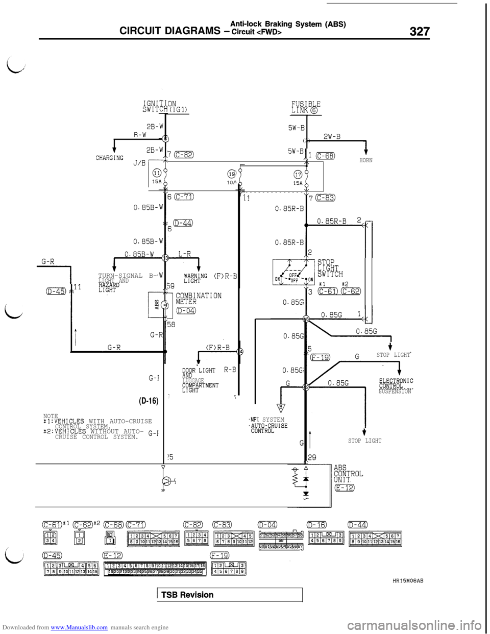
Downloaded from www.Manualslib.com manuals search engine Anti-lock Braking System (ABS)CIRCUIT DIAGRAMS - Circuit
IGNISWIT
2B-R-W
12B-
CHARGING J/B
0.85B-
0.858-
0.85B-WG-R
1TURN-SIGNAL B-LIGHT AND
L
G-I
(D-16)
NOTE:l:VEHICLES WITH AUTO-CRUISECONTROL SYSTEM.X2:VEHICLES WITHOUT AUTO- G-1CRUISE CONTROL SYSTEM.
ON(IGl)
5W-B
)(2)2W-B
7(c-82)5w-B,,1 (c-68)HORN
@0!OP15A
S(c-71)--------------II17m
59
#$"G (F)R-f
I
i;M;NATION
(D-04)
;l;R'LIGHT R-B
LUGGAGE~~~~~RTMENT
77
!5
3
0.85R-B
0.85R-B
0.85c:
0.85~
.MFI SYSTEM~EFR;FUISE
STOPLIGHTSWITCH
21:2cm (c-62)
5t
jF-19) GSTOP LIGHT
SUSPENSION
tSTOP LIGHT
ABSCONTROLUNIT
HRlSMOGAB
1 TSB Revision
Page 330 of 738
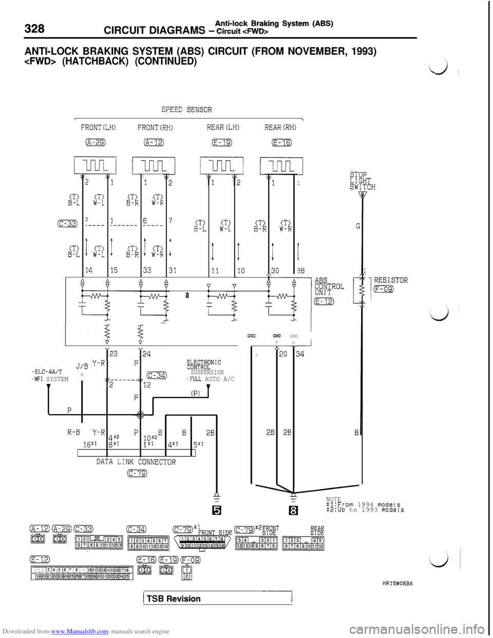
Downloaded from www.Manualslib.com manuals search engine 328Anti-lock Braking System (ABS)CIRCUIT DIAGRAMS - Circuit 4WD>
ANTI-LOCK BRAKING SYSTEM (ABS) CIRCUIT (FROM NOVEMBER, 1993)
cFWD> (HATCHBACK) (CONTINUED)
SPEED SENSOR
I\
FRONTCLH)FRONTCRH)REAR(LH)REAR(RH)
(A-29)(A-12)(E-19)(E-16)
CT)B-L2
1
(T)(T>W-LB-R
(c-33)3_----
CT)B-Li(T)W-L
:1
CT)W-F
16_---_------_
ICT>ICT>B-RW-I;
1533
7CT>CT)B-LCT)W-LB-F
I
i
31
1
11
I
10
!CT)W-R
:
30
2
t
28f,ABSCONTROLUNIT
m
14
1
RESISTOR
(F-09)a
GNDGNDGNDV
--.--I
34V
-
cr r2423”320
2B 28
J/B Y-R.ELC-4A/T
~LFXIC~~N’CA
SUSPENSION*MFI SYSTEM.FULL AUTO A/C1;;---m-Y-;lF2
(P)
P
R-BY-R422P B B 20lo:216:’ 8:’1:14:1 5:1
1DATA LINK CONNECTOR
(c-79)
nTNOTE%l:From 1994 moaels:2:UD to 1993 moaels
(E-(E-16)cFm19)(F-09)
1 [ 2 13 14 15 16 17 j 6 [ 9 ~10(11~12~13~14~15(16(17(18j19~20~21/22~3~24~5~6~7/26~29~0~1~32~33~34~35~ @ @@ BHR15MOGBA
( TSB Revision~~ ---I