key MITSUBISHI 3000GT 1992 2.G Repair Manual
[x] Cancel search | Manufacturer: MITSUBISHI, Model Year: 1992, Model line: 3000GT, Model: MITSUBISHI 3000GT 1992 2.GPages: 738, PDF Size: 35.06 MB
Page 514 of 738
Downloaded from www.Manualslib.com manuals search engine 54-18CHASSIS ELECTRICAL - Meters and Gauges
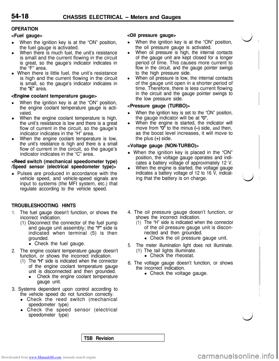
OPERATION
When the ignition key is at the “ON” position,the fuel gauge is activated.
l
When there is much fuel, the unit’s resistanceis small and the current flowing in the circuit
is great, so the gauge’s indicator indicates inthe “F” area.
l When there is little fuel, the unit’s resistance
is high and the current flowing in the circuit
is small, so the gauge’s indicator indicates inthe
“E” area.
lWhen the ignition key is at the “ON” position,
the engine coolant temperature gauge is acti-
vated.l
When the engine coolant temperature is high,
the unit’s resistance is low and there is a greatflow of current in the circuit, so the gauge’s
indicator indicates in the “H” area.
l
When the engine coolant temperature is low,
the unit’s resistance is high and there is a smallflow of current in the circuit, so the gauge’s
indicator indicates in the “C” area.
vehicle speed, and vehicle-speed signals areinput to systems (the MFI system, etc.) that
regulate according to the vehicle speed.
TROUBLESHOOTING HINTS
1.The fuel gauge doesn’t function, or shows the
incorrect indication.
(1) Disconnect the connector of the fuel pumpand gauge unit assembly; the ‘F” side is
indicated when terminal (5) is then
grounded.l Check the fuel gauge.
2.The engine coolant temperature gauge doesn’t
function, or shows the incorrect indication.
(1)The “l-l” side is indicated when the connector
of the engine coolant temperature gauge
unit is disconnected and then grounded.l
Check the engine coolant temperature
gauge unit.
3. Systems dependent upon control according to
the vehicle speed do not function correctly.l Check the reed switch (mechanical
speedometer type)l Check the speed sensor (electrical
speedometer type)
coil pressure gauge>l
When the ignition key is at the “ON” position,
the oil pressure gauge is activated.
lWhen oil pressure is high, the internal contacts
of the gauge unit are kept closed for a longerperiod of time. This causes more current to
flow in the circuit, and the gauge pointer swings
to the high pressure side.
lWhen oil pressure is low, the internal contactsof the gauge unit open in a shorter period of
time. Therefore, there is less current flowing
in the circuit and the gauge pointer swings to
the low pressure side.
lWhen the ignition key is set to the “ON” position,the gauge indicator will be at
“0”.l
When the engine is started, the indicator will
move from
“0” to the minus (-) side, and then,as the boost level increases, it will move to
the plus
(+) side.
position, the voltage gauge operates and indi-
cates a battery voltage of approximately 12 V.l
When the engine is started, the voltage gauge
indicates a battery voltage of 12 to 16 V, indicat-ing that the battery is on charge.
4. The oil pressure gauge doesn’t function, or
shows the incorrect indication.
(1)The “H” side is indicated when the connectorof the oil pressure gauge unit is discon-
nected and then grounded.l Check the oil pressure gauge unit.
5.The meter illumination light does not illuminate.
(1) The tail lights illuminate.l Check the rheostat.
6. The voltage gauge doesn’t function, or shows
the incorrect indication.l Check the voltage gauge.
TSB Revision
Page 535 of 738
Downloaded from www.Manualslib.com manuals search engine CHASSIS ELECTRICAL - Lighting System54-39
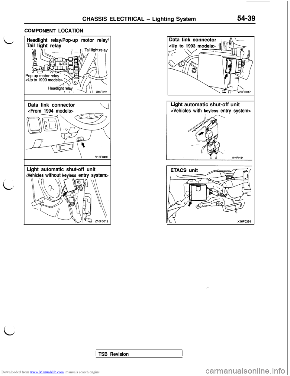
ZOMPONENT LOCATION
Headlight relay/Pop-up motor relay/
HeadliiW,$w, q\\ u,6F026,
Data link connector
\V16FO49E
Light automatic shut-off unit
-Light automatic shut-off unit
i
1 TSB Revision
Page 550 of 738
Downloaded from www.Manualslib.com manuals search engine 54-54CHASSIS ELECTRICAL - Lighting System
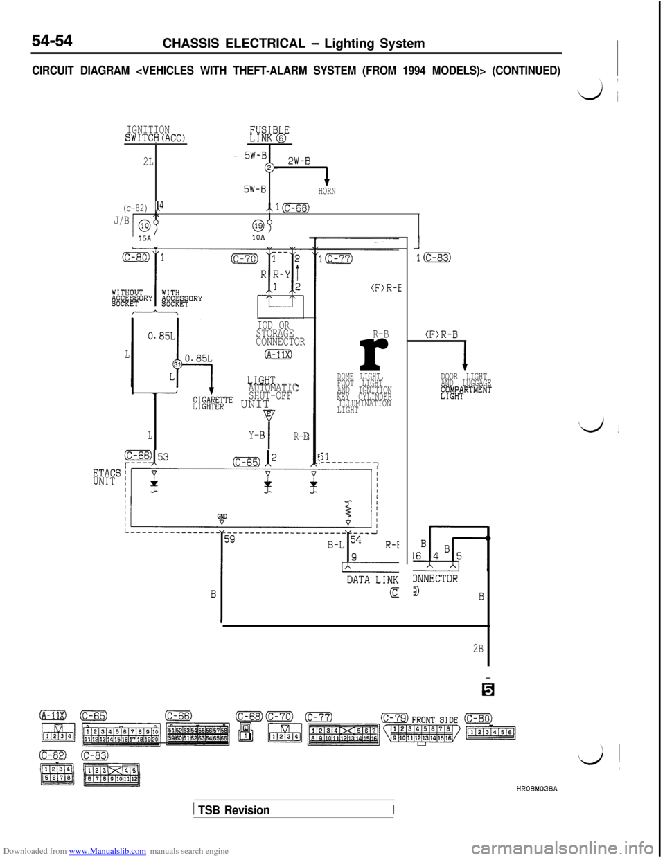
CIRCUIT DIAGRAM
IGNITIONSWITCH(ACC)I
2L2W-B
5W-BHORN
(c-82) ,P/x1=
J/Ba315A10A
IOD ORSTORAGE
CONNECTOR
L
AUTOMATIC
SHUT-OFF
L";@v;$TE UNITE
LYY-BR-E
(F>R-E
R-Br
DOME LIGHT,FOOT LIGHT
AND IGNITION
KEY CYLINDER
ILLUMINATION
LIGHT
51---------7
(F)R-B
2B
DOOR LIGHT
AND LUGGAGE
EWtRTMENT
d,
3NNECTOR
3I3HROBM03BA
1 TSB RevisionI
Page 559 of 738
Downloaded from www.Manualslib.com manuals search engine CHASSIS ELECTRICAL - Lighting System
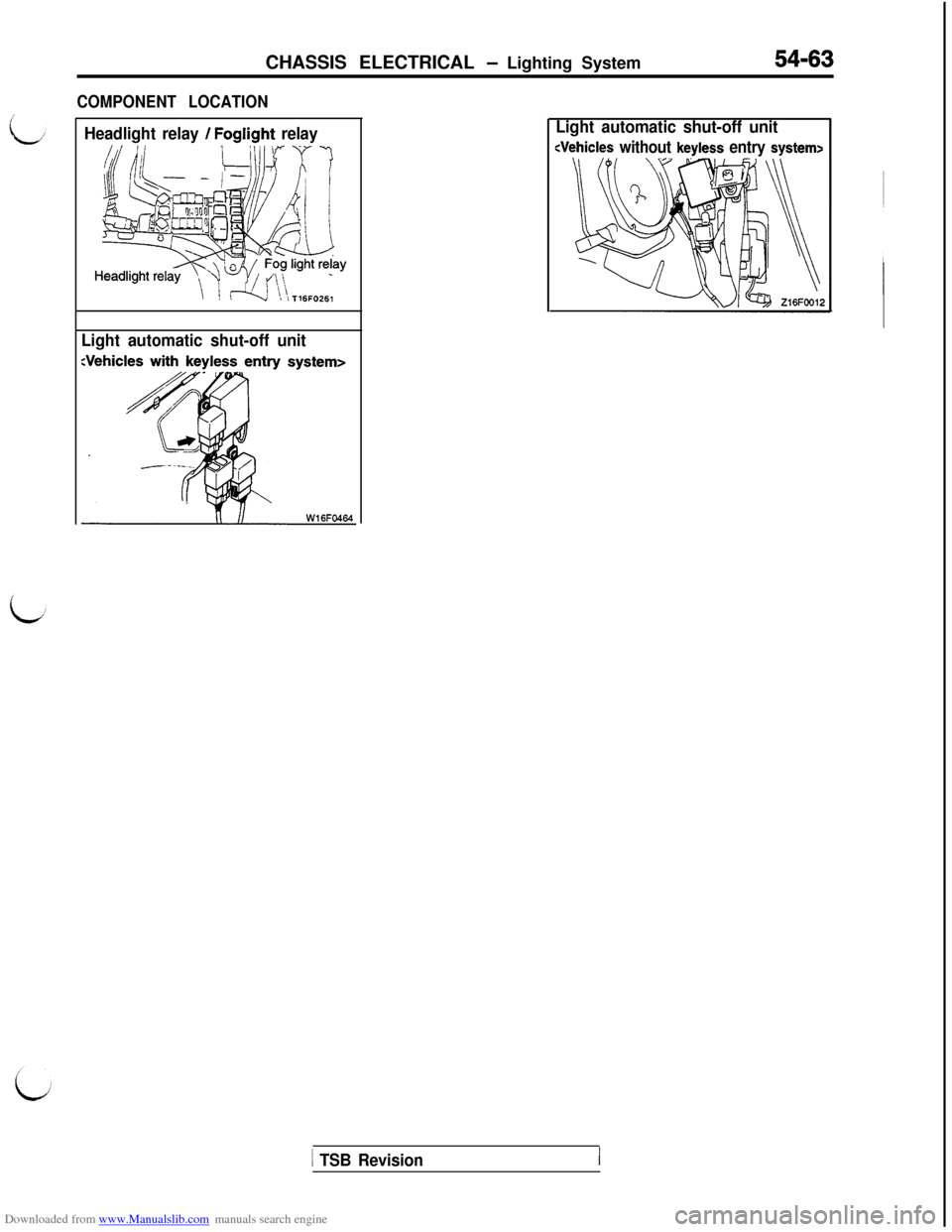
COMPONENT LOCATION
54-63
Headlight relay / Foglight relay
Light automatic shut-off unitLight automatic shut-off unit
1 TSB Revision
Page 567 of 738
Downloaded from www.Manualslib.com manuals search engine i;CHASSIS ELECTRICAL
- Lighting System54-71
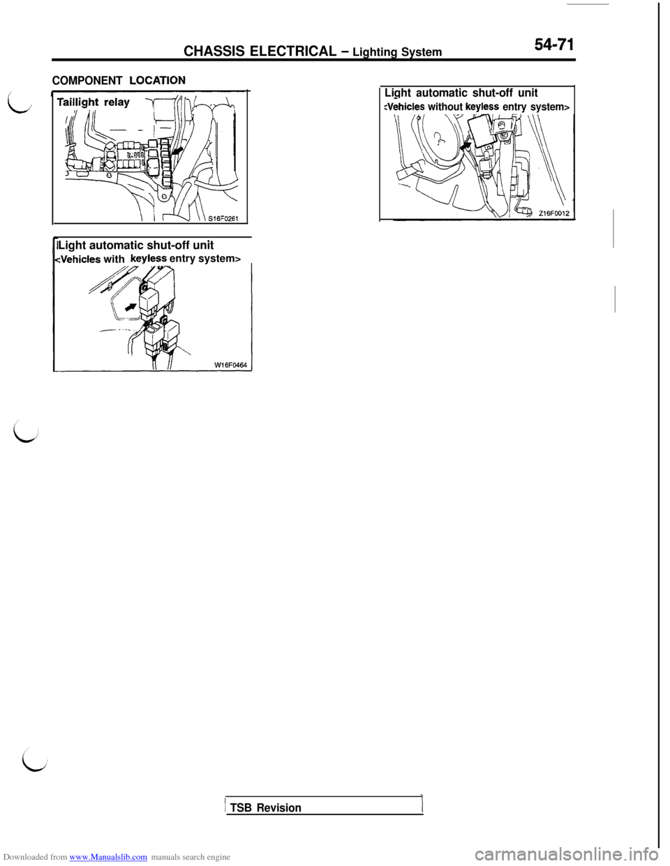
COMPONENT LOCATlON
.Light automatic shut-off unit
:Vehicles withkeyless entry system>
Light automatic shut-off unit
:Vehicles without keyless entry system>
1 TSB Revision
Page 568 of 738
Downloaded from www.Manualslib.com manuals search engine 54-72CHASSIS ELECTRICAL - Lighting System
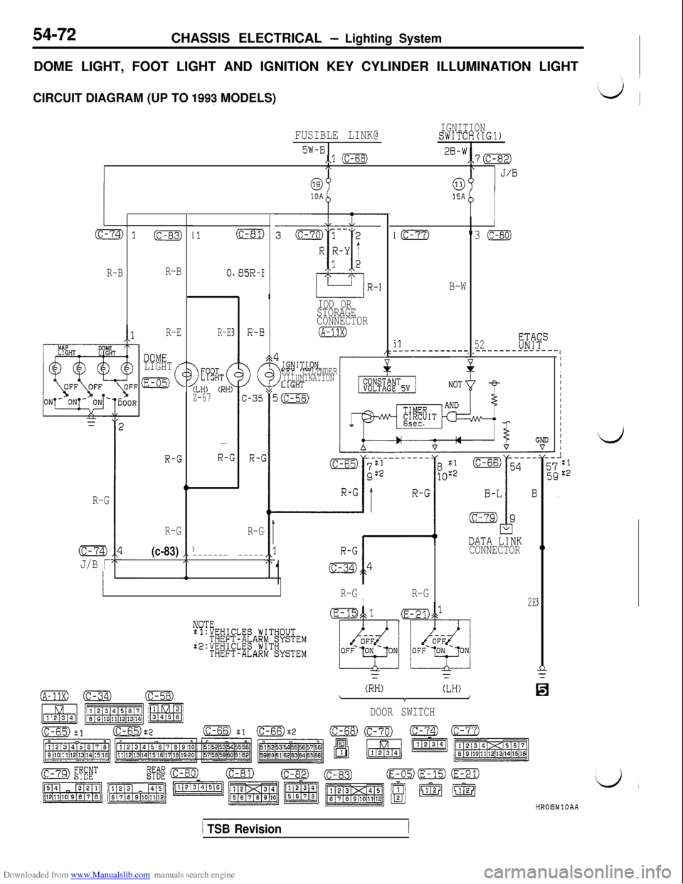
DOME LIGHT, FOOT LIGHT AND IGNITION KEY CYLINDER ILLUMINATION LIGHT
CIRCUIT DIAGRAM (UP TO
1993 MODELS)
FUSIBLE LINK@IGNITIONSWITCH(IGl)
5W-B,.l (c-68)2B-w,,7m/\\J/B
@0310A
L
(c-74)
R-B
I
IO"3 (c-80)
B-W
jl52;gF"___-_________ _----__--_-_--, IOD OR
STORAGE
CONNECTOR
(A-11X)
(c-83)
R-B
R-E
DOME
LIGHT
:E-05)(
R-G
I1(c-81)
0.85R-I
R-E
(LH) (RH:Z-67
-
R-c
$
KEY CYLINDERILLUMINATION
//
,
III
I
1IIIIIII
I
bIOOR
(c-74)
J/B r
(c-83))ICONNECTOR0------- -----
1
R-GIR-G2Ej
27
m(c-34)(c-58)(RH)(LH)\InY
DOOR SWITCH
d
R-G
R-G
d,HR08MlOAA
/ TSB Revision
Page 569 of 738
Downloaded from www.Manualslib.com manuals search engine CHASSIS ELECTRICAL - Lighting System
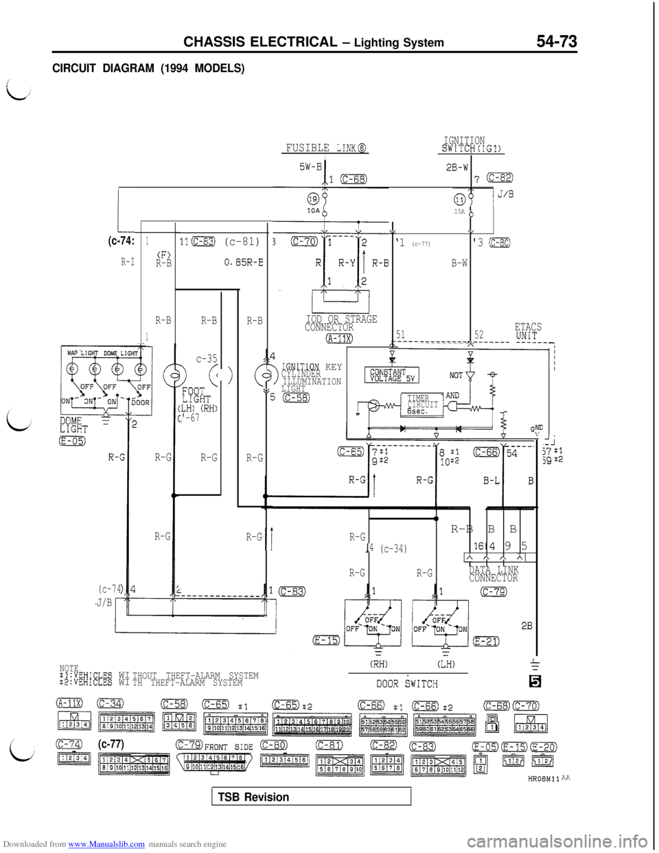
CIRCUIT DIAGRAM (1994 MODELS)54-73
IGNITIONSWITCH(IG1)IFUSIBLE L!NK@I5W-B2B-W
107m
1.
IOD OR STRAGE
CONNECTOR
(A-?1X)
15A (>
\I\/
‘1 (c-77)'3 (c-80)
B-W
51ETACS
__---_---------_____-_ !!1T--,52
(c-74:1
(F>R-B
R-B
1
ll(c-83) (c-81)
O.B5R-ER-I
>
R-B
R-B
c-35
) (<
FQO?LIGHTLH) (RH)'-67,
R-G
R-G
3>
!GNITION KEYCYLINDERILLUMINATION\gLIGHTEi(c-58)TIMERCIRCUIT6sec.
0
,iR-GR-B B B
,,4 (c-34)lE4 9 5
IA A * Al
R-G
R-GDATA LINK
CONNECTOR R-G
R-G
.NDV
AJj7:1jgZ2
(c-74
J/BR-G
NOTE:l:VEHICLES WI:2:VEHiCLES WITHOUT THEFT-ALARM SYSTEM
TH THEFT-ALARM SYSTEM
(RH)(LH)
DooR SWITCH
(c-77)OFRONT SIDE (C-80)(c-81)(c-82)AA
TSB Revision
Page 570 of 738
Downloaded from www.Manualslib.com manuals search engine 54-74CHASSIS ELECTRICAL - Lighting System
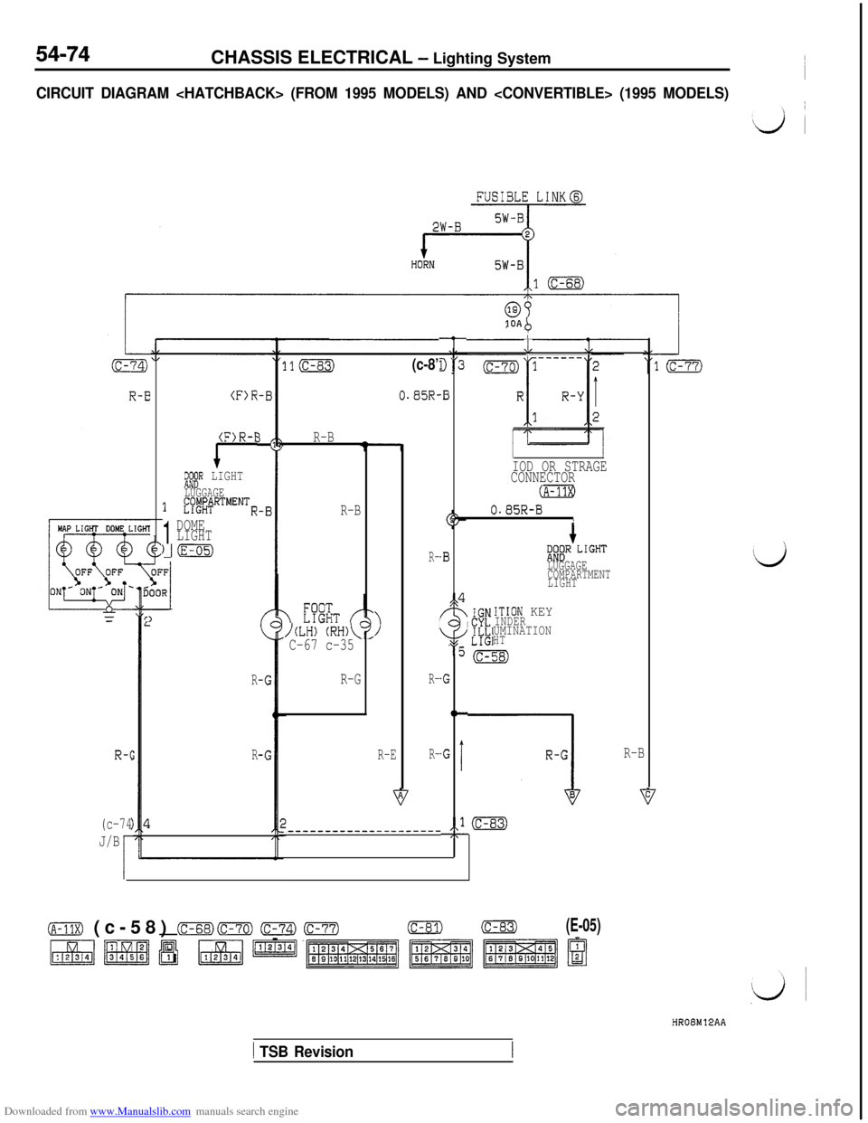
CIRCUIT DIAGRAM
R-c
(c-74
J/B
1i$X&R LIGHT
LUGGAGE1 fy##RTMENTR
1
DOME
LIGHT
Jm)
R
R
R-B
R-B
)(LH) (RH)\IC-67 c-35
R-G
>
R-E
(c-8’
0.85R-
R-
I
R-
R-
---------------------
10Ab-
,il3
.B
9
.B
s$4
fY
\7/
“5
.G
(C
,GI
,l-77
0.85R-B.
ITION KEYINDERUMINATIONHT
(c-83)
L\,
IOD OR STRAGE
CONNECTOR
(A-11X)
XW8” L1GHTLUGGAGE
COMPARTMENT
LIGHT
R-B
(A-11X) (c-58) (c-68)cm) (c-74) (c-77)(c-81)(c-83)(E-05)
~plmp?JJ ~I~~~IRi~l~
HR08Ml2AA
1 TSB Revision
Page 572 of 738
Downloaded from www.Manualslib.com manuals search engine 54-76CHASSIS ELECTRICAL - Lighting System
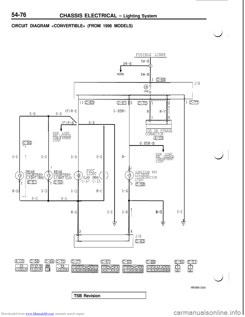
CIRCUIT DIAGRAM
FUSIBLE LINK@
J/B
R-E
R-BII
R-E
>
~REARICOURTESY I;LIGHT(RH:(
/pg
IIIR-C/'-iR-GR-B
(F)R-E
DOOR LIGHTAND UGGAGE!ACOMP RTMENT
LIGHT
R-B
1
>
[(E-50)
R-C
R-G
R-6
0.85R-
R-B
R-E
>
FOOT
LIGHT
(LH) (RH)(C-67 C-35
R-c
>
R-E
R-
(
R-
R-
>
IGNITION KEYCYLINDERILLUMINATION
LIGHT
l(c-58)
I
----I
R-G
B
I
J/B
(c-s3)
IOD OR STRAGE
CONNECTOR
(A-11XI
0.85R-B
DOOR LIGHT
AND LUGGAGE
COMPARTMENT
LIGHT
R-E
HROBMlSAA
TSB Revision
Page 574 of 738
Downloaded from www.Manualslib.com manuals search engine 54-78CHASSIS ELECTRICAL - Lighting System
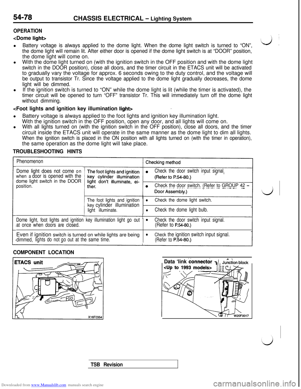
OPERATION
Battery voltage is always applied to the dome light. When the dome light switch is turned to “ON”,
the dome light will remain lit. After either door is opened if the dome light switch is at “DOOR” position,the dome light will come on.
lWith the dome light turned on (with the ignition switch in the OFF position and with the dome light
switch in the DOOR position), close all doors, and the timer circuit in the ETACS unit will be activatedto gradually vary the voltage for approx. 6 seconds owing to the duty control, and the voltage will
be output to transistor Tr. Since the voltage applied to the dome light gradually decreases, the dome
light will be dimmed.lIf the ignition switch is turned to “ON” while the dome light is lit (while the timer is activated), the
timer circuit will be opened to turn “OFF” transistor Tr. This will immediately turn off the dome light
without dimming.
With the ignition switch in the OFF position, open any door, and all lights will come on.
l
With all lights turned on (with the ignition switch in the OFF position), close all doors, and the timercircuit inside the ETACS unit will operate in the same manner as the dome light to dim all lights.
When the ignition switch is placed in the ON position with all lights turned on (with the timer in operation),the same operation as the dome light will take place.
TROUBLESHOOTING HINTS
Phenomenon
Dome light does not come on
when
a door is opened with the
dome light switch in the DOOR
position.
Check the door switch input signal.
Check the door switch. (Refer to GROUP 42 -
The foot lights and ignitionl
key cylinder illumination
Check the dome light switch.
light illuminate.
lCheck the dome light bulb.
Dome light, foot lights and ignition key illumination light go out
l
at once when doors are closed.Check the door switch input signal.(Refer to P.54-80.)Even if ignition switch is turned on while lights are being
l
dimmed,lightsdo notout at the same time.
Check the ignition switch input signal.
go
(Refer toP.54-80.)
COMPONENT LOCATION
Data ‘link
connect&
TSB Revision