key MITSUBISHI 3000GT 1992 2.G Manual Online
[x] Cancel search | Manufacturer: MITSUBISHI, Model Year: 1992, Model line: 3000GT, Model: MITSUBISHI 3000GT 1992 2.GPages: 738, PDF Size: 35.06 MB
Page 726 of 738
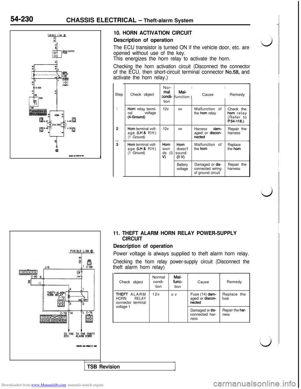
Downloaded from www.Manualslib.com manuals search engine .,i”i, LlNl Q10. HORN ACTIVATION CIRCUIT
?a/ ;
dl
spored10.
Description of operation
The ECU transistor is turned ON if the vehicle door, etc. are
opened without use of the key.
This energizes the horn relay to activate the horn.
Checking the horn activation circuit (Disconnect the connector
of the ECU, then short-circuit terminal connector No.58, and
activate the horn relay.)
54-230CHASSIS ELECTRICAL - Theft-alarm System
z “2
EL? II A-as ’
I3 Ii3
c!
ig”‘“,1 u~cw ~ I A.,Op+J
x
6IZ)Y.l,.-”Step
1Check objectmatMal-
I Icondi- functionCauseRemedy
Horn relay termi-nalvoltage(4-Ground)12v ovMalfunction of
Check thethe horn relayhorn relay
(Refer to
P.54-118.)
Horn terminal volt-12v ovHarnessdam-age (LH & RH)Repair the
aged or discon-harness(1 -Ground)netted
Horn terminal volt-age (LH & RH)(1 -Ground)Nor-
1IItion
HornHornMalfunction ofReplacesoundoesn’tthe hornthe hornds (0 sound
V)(0 w
BatteryDamaged or dis-Repair thevoltageconnected wiringharness
of ground circuit
11. THEFT ALARM HORN RELAY POWER-SUPPLY
CIRCUIT
Description of operation
Power voltage is always supplied to theft alarm horn relay.
Checking the horn relay power-supply circuit (Disconnect the
theft alarm horn relay)Check object
THEFT ALARMHORNRELAYconnector terminal
voltage 1NormalMal-
condi-func-
CauseRemedy
tion
tion
12v
ovFuse (14)
dam-Replace the
aged or discon-fusenetted
Damaged or dis-Repair the har-connected har-nessness
TSB Revision
Page 727 of 738
Downloaded from www.Manualslib.com manuals search engine i
LCHASSIS ELECTRICAL
- Theft-alarm System54-231
Fwbklink (6)A-26
8=’ Theft-
alarm
ECUA 27
i
1 *horn
al
Z16FO342
TO Ecu
auO-U-RS4I2-YI
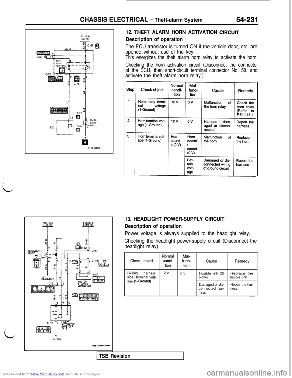
12. THEFT ALARM HORN ACTIVATION ClRCUlT
Description of operation
The ECU transistor is turned ON if the vehicle door, etc. are
opened without use of the key.
This energizes the theft alarm horn relay to activate the horn.
Checking the horn activation circuit (Disconnect the connector
of the ECU, then short-circuit terminal connector No. 58, and
activate the theft alarm horn relay.)
13. HEADLIGHT POWER-SUPPLY CIRCUIT
Description of operation
Power voltage is always supplied to the headlight relay.
Checking the headlight power-supply circuit (Disconnect the
headlight relay)
Check objectNormalMal-condi-func-CausetiontionRemedy
(Wiring
harness12 vovside) terminal volt-Fusible link (3)Replace theblownfusible link
age (5-Ground)Damaged or dis-Repair the har-connected har-nessness
1 TSB Revision
Page 728 of 738
Downloaded from www.Manualslib.com manuals search engine 54-232CHASSIS ELECTRICAL - Theft-alarm System
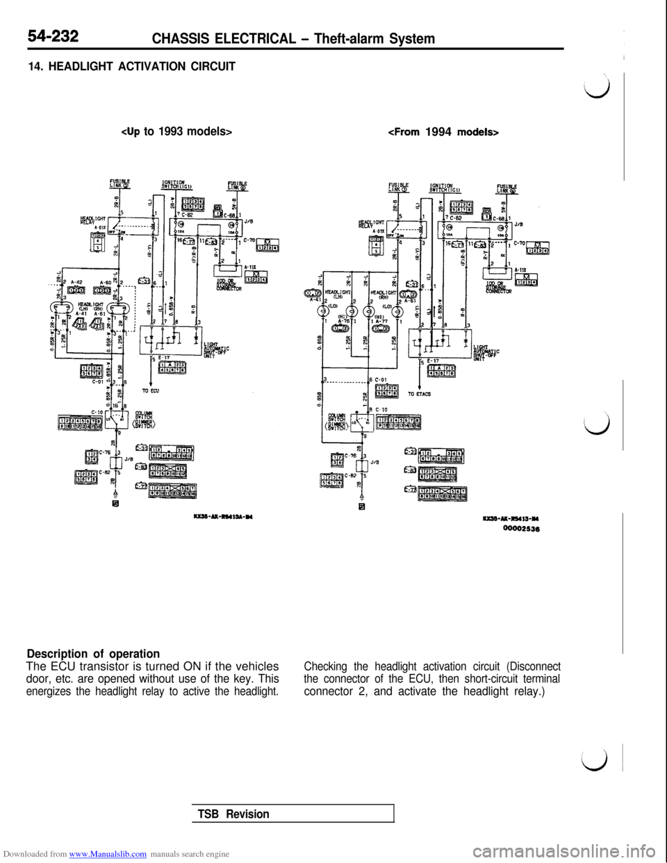
14. HEADLIGHT ACTIVATION CIRCUIT
k&w; s’._____.om-
R
43-? -R5
Ic-m 3
*
JOtaC-82 5w
ii
Description of operationThe ECU transistor is turned ON if the vehicles
door, etc. are opened without use of the key. This
energizes the headlight relay to active the headlight.Checking the headlight activation circuit (Disconnect
the connector of the ECU, then short-circuit terminalconnector 2, and activate the headlight relay.)
TSB Revision
Page 730 of 738
Downloaded from www.Manualslib.com manuals search engine 54-234CHASSIS ELECTRICAL - Theft-alarm System
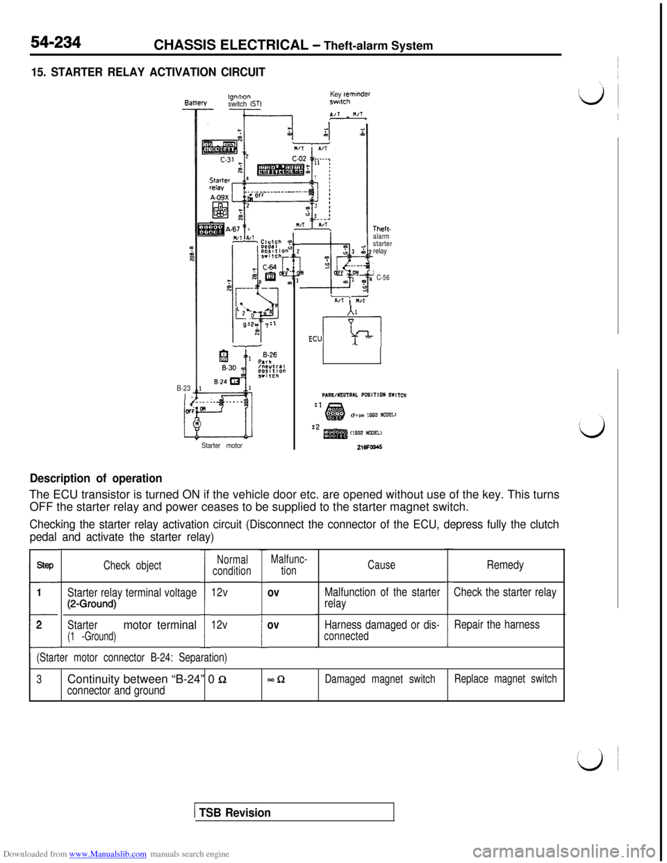
15. STARTER RELAY ACTIVATION CIRCUIT
lgnlllonKey reminderBattery
switch (STIswtch
B-23l-
Starter motor
Lo03 52“:
&Y
. ..--N. OYa.’ ‘pa3
PI/l i M/T
Theft-
alarm
starter
relay
IC-56
A1
ECUm
PANWNEUTNLl. PONlTlON WITCH:1(prom 1993 NODEL)
:2cm2 N@nEL>216Fcas
Description of operationThe ECU transistor is turned ON if the vehicle door etc. are opened without use of the key. This turns
OFF the starter relay and power ceases to be supplied to the starter magnet switch.
Checking the starter relay activation circuit (Disconnect the connector of the ECU, depress fully the clutch
pedal and activate the starter relay)
SW
1
t
2Check object
Starter relay terminal voltage
(2-Ground)
Startermotor terminal
(1 -Ground)I
Normal
condition
12v
12v
:
Malfunc-
tion
ov
ov
Cause
Malfunction of the starter
relay
Harness damaged or dis-
connected:
Remedy
Check the starter relay
Repair the harness
(Starter motor connector B-24: Separation)
3Continuity between “B-24” 0
Q-clDamaged magnet switchReplace magnet switch
connector and ground
( TSB Revision
Page 733 of 738
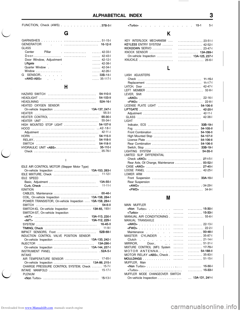
Downloaded from www.Manualslib.com manuals search engine ALPHABETICAL INDEX3FUNCTION, Check (4WS) .
. . . . . . . . . . . .37B-5-l
GARNISHES . . . . . . . . .
GENERATOR . .
GLASSCenter Pillar .
Door.....................
Door Window, Adjustment
Liftgate . .Quarter Window.Window. . . . . . . . . . . . . . . .G SENSOR.. . . . . .
G
.........................51-15-l........................16-12-11
.....................42-33-l.....................42-43-l......42-12-l......42-38-l......42-34-l......42-26-l....338-l 8-l.....35-117-l
H
HAZARD SWITCH..................................54-110-11
HEADLIGHT........................................54-103-11
HEADLINING.......................................52A-16-l
HEATED OXYGEN SENSOROn-vehicle Inspection.........................13A-137,247-l
HEATER..............................................55-3-l
HEATER CONTROL...................................55-30-I
HEATER UNIT........................................55-34-l
HIGH MOUNTED STOP LIGHT.......................54-107-11
HOOD...............................................42-18-lAdjustment.........................................42-11 -I
HORN.............................................54-115-11RELAY..
..........................................54-118-11
SWITCH..........................................54-118-11
HYDRAULIC UNIT CABS>.............................35-110-I
Check
.............................................35-76-lI
IDLE AIR CONTROL MOTOR (Stepper Motor Type)
On-vehicle Inspection.........................13A-153,263-l
IDLE MIXTURE, Check................................11-12-l
IDLE SPEED
Basic, Adjustment.................................13A-55-lCurb,Check........................................11-11-l
IGNITION
CABLES, Maintenance................................00-46-l
COIL, On-vehicle Inspection....................
13A-158,264-l
POWER TRANSISTOR, On-vehicle Inspection....13&158,264-l
SWITCH............................................54-6-11
SWITCH-IG, On-vehicle Inspection...............13A-65, 193-l
SWITCH-ST, On-vehicle Inspection
......................................13A-113,230-l
SYSTEM...........................................16-45-11
TIMING,‘Check.......................................11-9-l
IMPACT SENSORS, Front............................528-68-I
INDUCTION CONTROL VALVE POSITION SENSOROn-vehicle Inspection.........................13A-133,242-l
INJECTOR........................................13A-286-l
On-vehicle Inspection.........................
13A-144,257-l
INSTRUMENT PANEL.................................52A-5-lINTAKE
AIR TEMPERATURE SENSOR........................17-65-l
On-vehicle Inspection..........................13A-88,215-l
CHARGE PRESSURE CONTROL SYSTEM, Check.......15-7-l
INTAKE MANIFOLD...................................15-17-l
PLENUM
K
KEY INTERLOCK MECHANISM....KEYLESS ENTRY SYSTEM........KICKDOWN SERVO...............KNOCK SENSOR.................On-vehicle Inspection............KNUCKLE........................
.................23-51-l.................42-52-l.................23-47-l..............13A-289-l..........
13A-125,237-l..................26-6-l
L
LASH ADJUSTERSCheck.............................................11-15-lReplacement.......................................11-l 7-l
LATCH, Door.........................................42-47-lLEFT MEMBER........................................32-8-l
LEVER, Shift
cFWD>.............................................22-8-lLICENSE PLATE LIGHT.............................54-106-11
LIFTGATE............................................42-20-I
Adjustment.........................................42-11-l
GLASS.............................................42-38-lLIGHT
Indicator, ECS....................................338-19-IFog.............................................54-105-11Front Combination.................................54-106-11High Mounted Stop................................54-107-11License Plate.....................................54-106-11
Rear Combination.................................54-106-11Switch, Stop......................................33B-19-l
LIGHTING SYSTEM..................................54-35-11LIMITED SLIP DIFFERENTIALCheck cAWD>......................................27-l 5-l
Rear Axle, Oil Change, Maintenance...................00-52-I
CASE
LOOSE PANEL.......................................42-25-l
LOWER ARM
Front Suspension.................................33A-10-I
Rear Suspension
M
MAIN MUFFLER
MANUAL AIR CONDITIONING .
MANUAL TRANSAXLE
cFWD> . . . . . . . . . . . .Maintenance. . . . .
MASTER CYLINDER . . .
Clutch . . . . . . . .
MIRROR, Door..
_. .MIXTURE CONTROL (MFI) SystemMOTOR ANTENNA.. . . .
MOTOR RELAY
CABS>, Check .MOULDINGS . . . . . . . . . . . . .MUFFLER, Main
.....................
.......
...............................................................
..........15-30-I..........
15-33-l...........55-6-l..........
22-13-l...........22-2-l..........00-48-I..........35-87-l..........21-14-l..........51-31-l..........17-70-I........54-188-11..........35-83-l..........51-15-l...........
15-30-I..........15-33-l...
13A-131,241-l