MITSUBISHI 3000GT 1992 2.G Workshop Manual
Manufacturer: MITSUBISHI, Model Year: 1992, Model line: 3000GT, Model: MITSUBISHI 3000GT 1992 2.GPages: 738, PDF Size: 35.06 MB
Page 601 of 738
Downloaded from www.Manualslib.com manuals search engine CHASSIS ELECTRICAL - Lighting System54-105FOG LIGHT
REMOVAL AND INSTALLATION
(Up to 1993 models)
,’
..-.-f .- . . .._ 1’yI’-’--.._ . . . ./’‘._,/‘.:‘. . . . . .--ye=.,/‘c’ !:I’:.;; ____-... _.__-.-__~___. . . . . ._./i L.- -3...-.._:.y- .‘...-____ y--. . . . . --‘-T---..-_ -_--._ _ __.-.-.;.? ::.._/ ; .--_.‘7 ,,-y-? ..-,r-; ‘;
‘....lr/I..j ,/L7 rl,-’/I” . . . ..-. ~ -,-.-A:..____ p
A’7----p--*@
,,A..
*~~~~1;’ -“‘.,.
, ‘!U ,.I,/ Ii
8, $&$Jqk2&
4&;. +I+ ’
,,, ’ .’- ‘-I,i
4!a
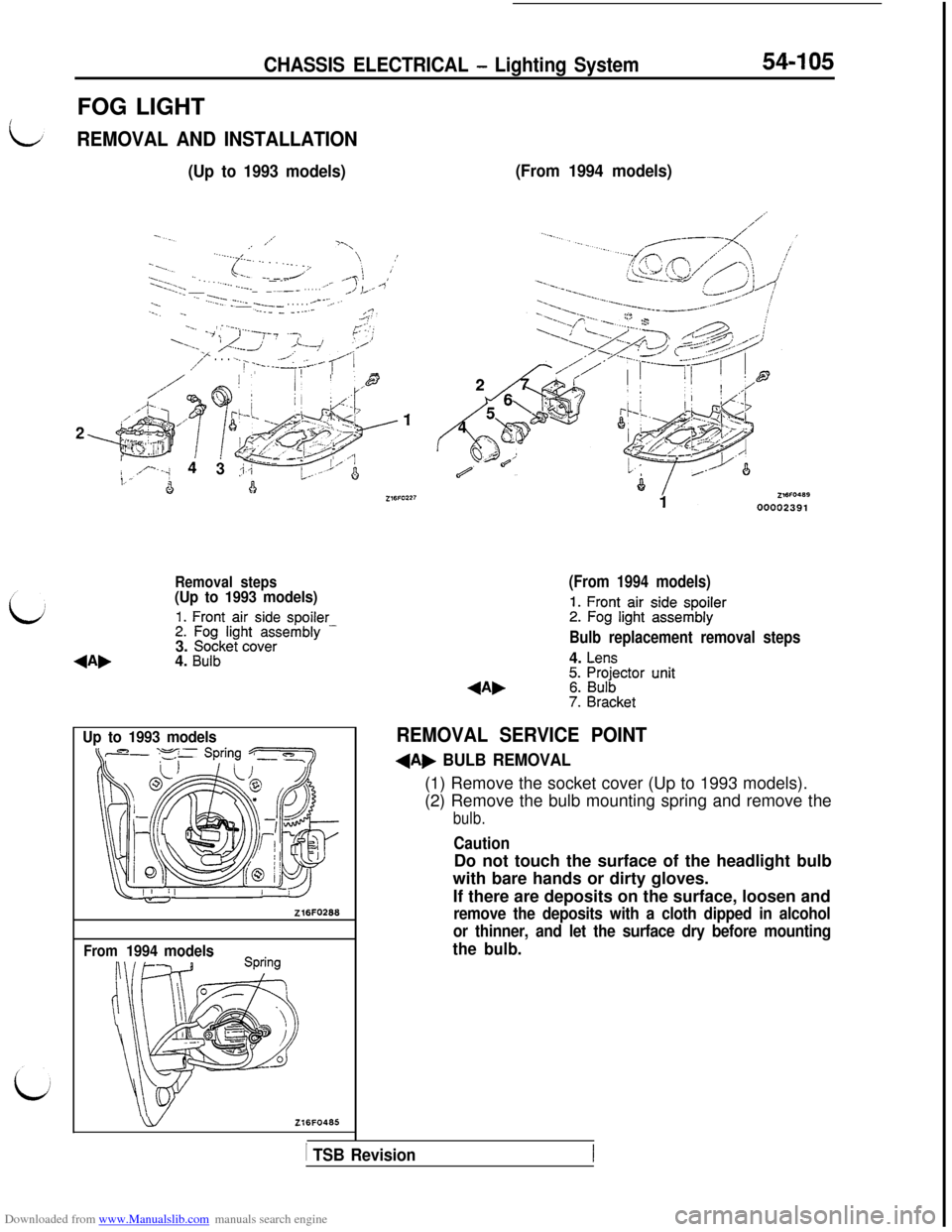
Removal steps(Up to 1993 models)
1. Front air side spoiler2. Fog light assembly -3. Socket cover4. Bulb
Up to 1993 models
Z16FO268
From1994 models
wZl6FO465
(From 1994 models)
(From 1994 models)
1. Front air side spoiler2. Fog light assembly
Bulb replacement removal steps4.
Lens5. Projector unit6. Bulb7. Bracket
REMOVAL SERVICE POINT
+A, BULB REMOVAL(1) Remove the socket cover (Up to 1993 models).
(2) Remove the bulb mounting spring and remove the
bulb.
CautionDo not touch the surface of the headlight bulb
with bare hands or dirty gloves.
If there are deposits on the surface, loosen and
remove the deposits with a cloth dipped in alcohol
or thinner, and let the surface dry before mounting
the bulb.
1 TSB Revision
Page 602 of 738
Downloaded from www.Manualslib.com manuals search engine 54-106CHASSIS ELECTRICAL - Lighting SystemFRONT COMBINATION LIGHT AND OPTICAL HORN LENS
REMOVAL AND INSTALLATION(Up to 1993 models)
j&z?&/ optica’ horn Iens
(From 1994 models)
L.JZ16FO216Z16FO47600002392
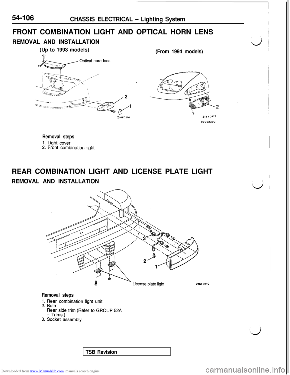
Removal steps
1. Light cover2. Front combination lightREAR COMBINATION LIGHT AND LICENSE PLATE LIGHT
REMOVAL AND INSTALLATION
I
#d ~
216FO210
Removal steps
1. Rear combination light unit2. Bulb
Rear side trim (Refer to GROUP 52A- Trims.)
3. Socket assembly
TSB Revision
Page 603 of 738
Downloaded from www.Manualslib.com manuals search engine CHASSIS ELECTRICAL - Lighting SystemHIGH MOUNTED STOP LIGHT
REMOVAL AND INSTALLATION
Z 16FO229Z 16FO229
‘\ \/4
116FcJ23100002393 00002393
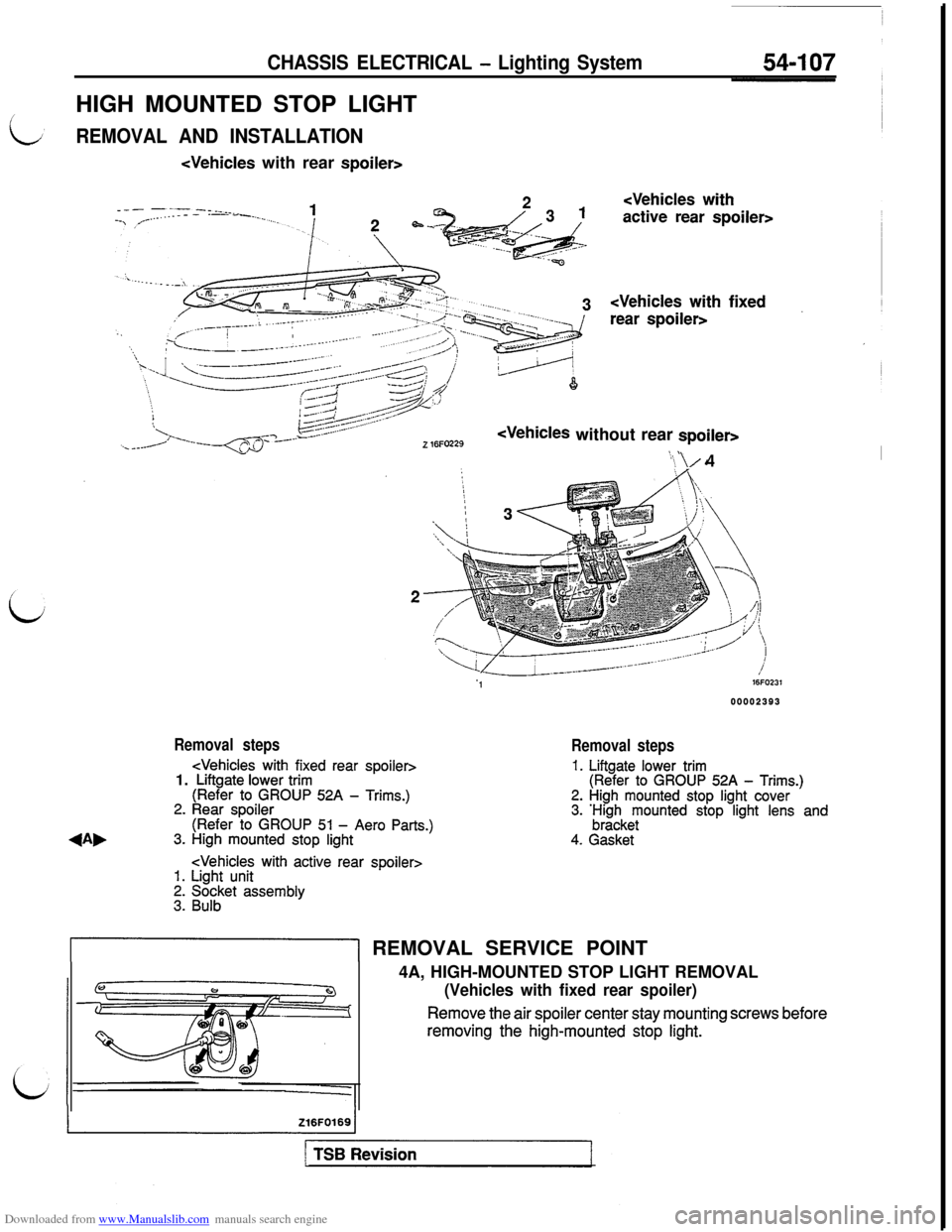
Removal steps
Removal steps
1. Liftgate lower trim(Refer to GROUP 52A - Trims.)2. High mounted stop light cover3. ;;z;keyounted stop light lens and
4. Gasket
&I REMOVAL SERVICE POINT
4A, HIGH-MOUNTED STOP LIGHT REMOVAL
(Vehicles with fixed rear spoiler)
Remove the air spoiler center stay mounting screws beforeremoving the high-mounted stop
light.
Page 604 of 738
Downloaded from www.Manualslib.com manuals search engine 54-108
CHASSIS ELECTRICAL - Lighting System
1 ‘-‘FE%!oooou2394
Y18AOO61
RELAY
INSPECTIONHEADLIGHT RELAY
/ TAILLIGHT RELAY / FOG LIGHT
RELAY CHECK
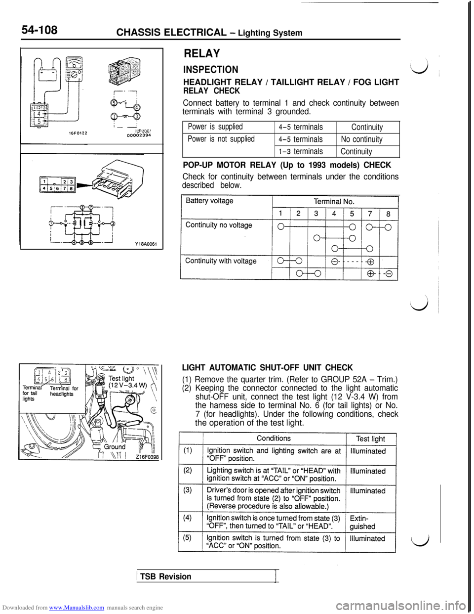
Connect battery to terminal 1 and check continuity between
terminals with terminal 3 grounded.
Power is supplied4-5 terminals
Continuity
Power is not supplied4-5 terminalsNo continuity
1-3 terminals
Continuity
POP-UP MOTOR RELAY (Up to 1993 models) CHECK
Check for continuity between terminals under the conditions
described below.
LIGHT AUTOMATIC SHUT-OFF UNIT CHECK
(1) Remove the quarter trim. (Refer to GROUP 52A - Trim.)
(2) Keeping the connector connected to the light automatic
shut-OFF unit, connect the test light (12 V-3.4 W) from
the harness side to terminal No. 6 (for tail lights) or No.
7 (for headlights). Under the following conditions, checkthe operation of the test light.
id
/ TSB Revision
Page 605 of 738
Downloaded from www.Manualslib.com manuals search engine CHASSIS ELECTRICAL - Lighting System54-109
POP-UP SWITCH* AND FOG LIGHT SWITCH
i
LREMOVAL AND INSTALLATION
bZ16FO220
b
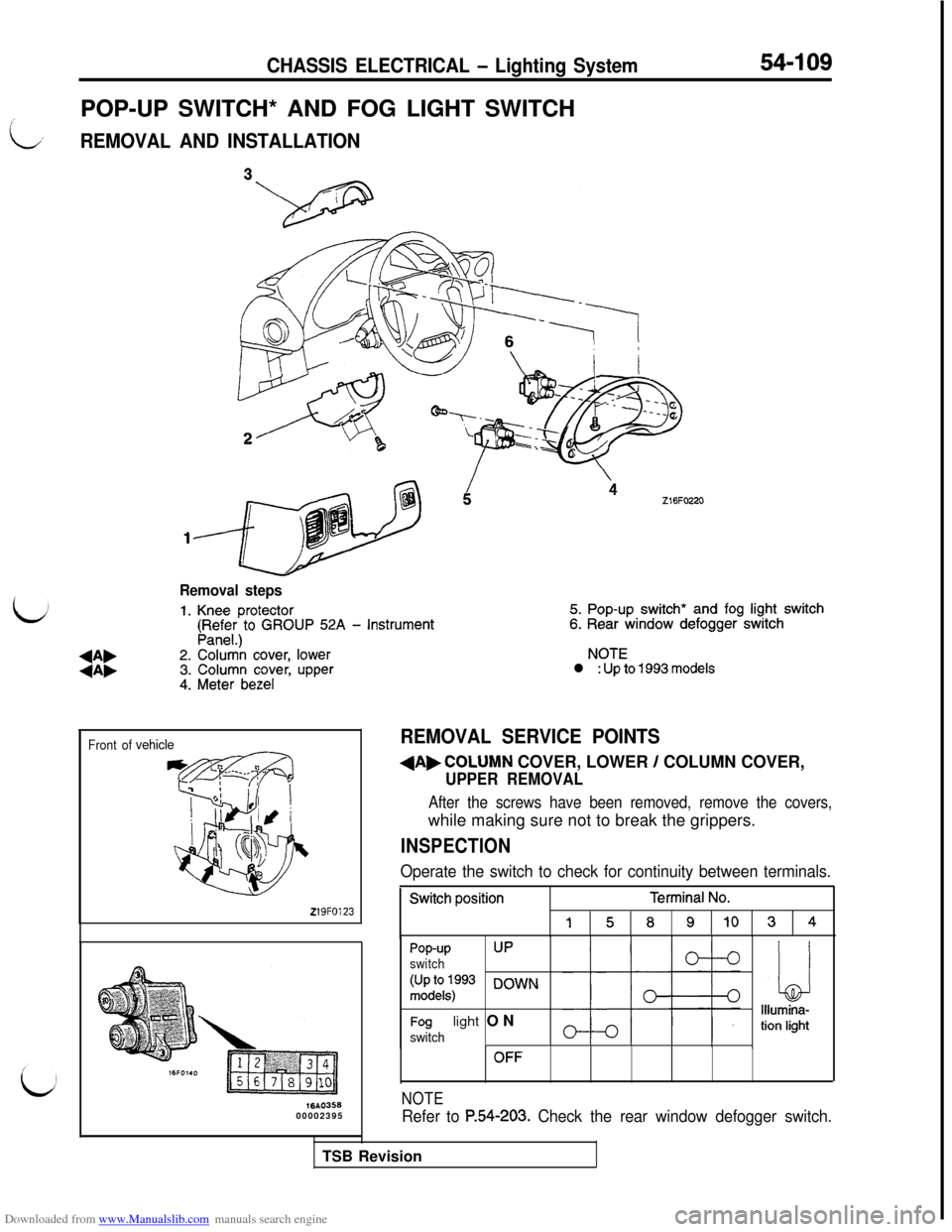
Removal steps
1. Knee protector5. Pop-up switch* and fog light switch
(pR,;$)to GROUP 52A - Instrument6. Rear window defogger switch
+A,2. Colur& cover, lowerNOTE
+A,3. Column cover, upperl : Up to 1993 models
4. Meter bezel
Front ofvehicle
219FO123
lbA035600002395
REMOVAL SERVICE POINTS
dAbCOLUMN COVER, LOWER / COLUMN COVER,
UPPER REMOVAL
After the screws have been removed, remove the covers,while making sure not to break the grippers.
INSPECTION
Operate the switch to check for continuity between terminals.
Switch positionTerminal No.
15891034
Pop-upUP
switch
:;;1kq:p93 DOWN
Foglight ONswitch
OFF
NOTE
Refer to P.54-203. Check the rear window defogger switch.TSB Revision
Page 606 of 738
Downloaded from www.Manualslib.com manuals search engine 54-110CHASSIS ELECTRICAL - Lighting System
1
16FO121
16FO12600002396
I‘VA1 I\ Air outlet assembly _I
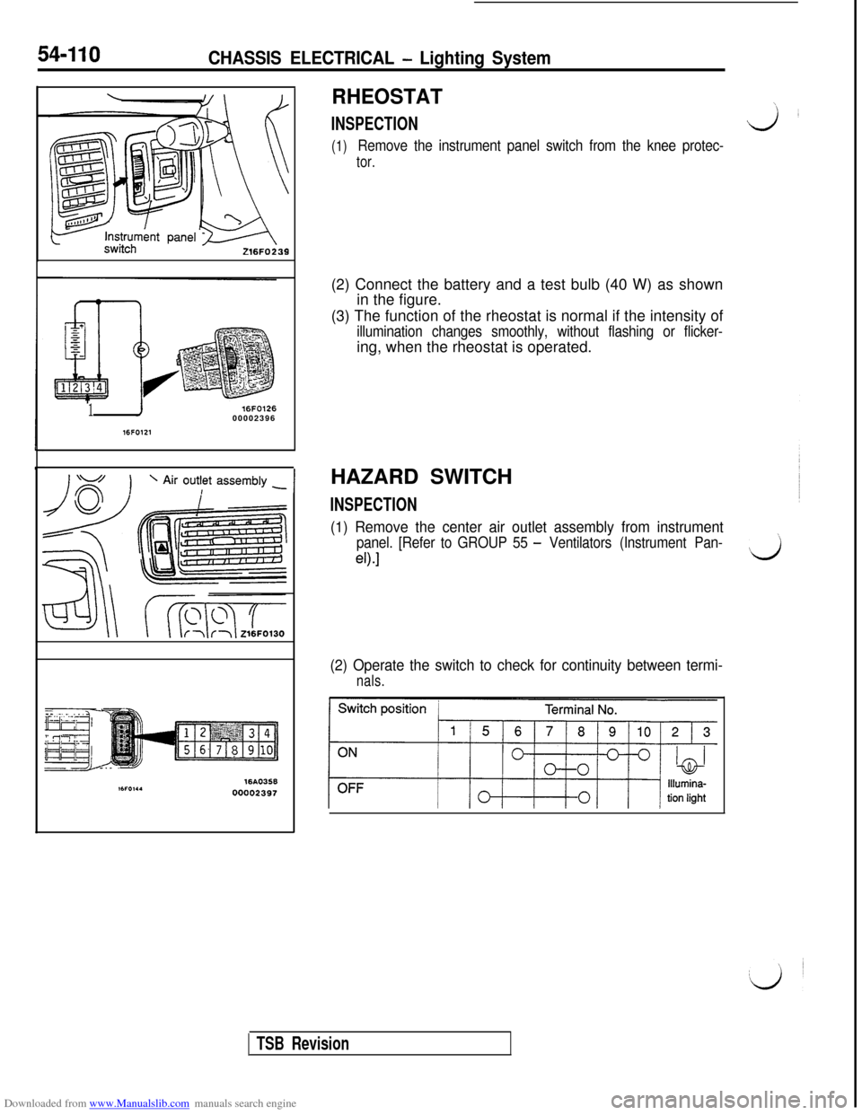
RHEOSTAT\
INSPECTIONJL
(1)Remove the instrument panel switch from the knee protec-
tor.(2) Connect the battery and a test bulb (40 W) as shown
in the figure.
(3) The function of the rheostat is normal if the intensity of
illumination changes smoothly, without flashing or flicker-ing, when the rheostat is operated.
HAZARD SWITCH
INSPECTION
(1) Remove the center air outlet assembly from instrument
panel. [Refer to GROUP 55 - Ventilators (Instrument Pan-’
eO.1d
(2) Operate the switch to check for continuity between termi-
nals.
TSB Revision
Page 607 of 738
Downloaded from www.Manualslib.com manuals search engine CHASSIS ELECTRICAL - Column Switch
COLUMN SWITCH
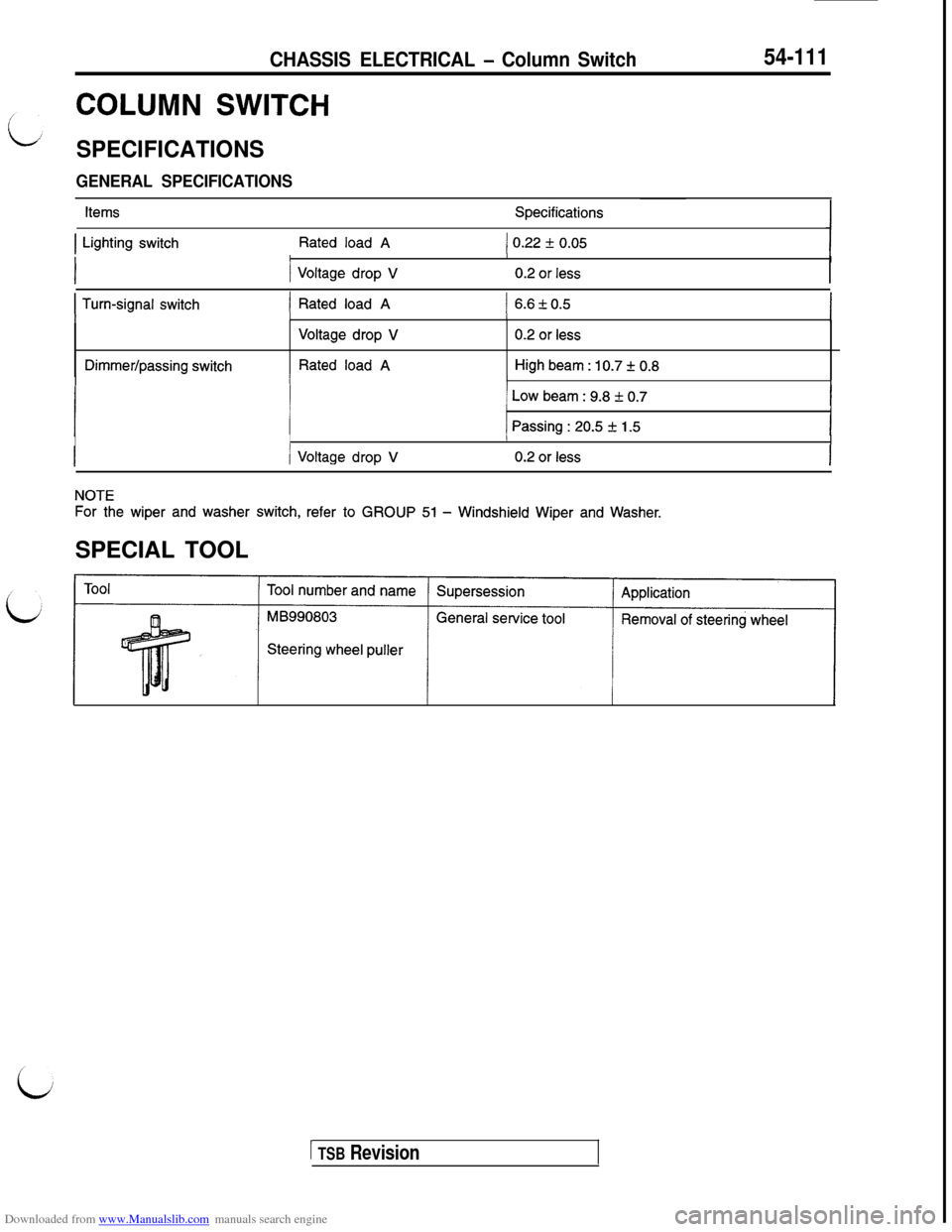
SPECIFICATIONS
GENERAL SPECIFICATIONS
54-111
ItemsSpecifications
1 Lighting switchRated load A1 0.22 f 0.05IIII
1 Voltage drop V0.2 or less
I Turn-signal switch) Rated load A1 6.6kO.5III/I
Dimmer/passing switch
Voltage drop V
Rated load A
0.2 or less
High beam : 10.7 + 0.8IIII
1 Low beam : 9.8 f 0.7IIII
j Passing : 20.5 + 1.5IIII
/ Voltage drop V0.2 or less
NOTE
For the wiper and washer switch, refer to GROUP 51 - Windshield Wiper and Washer.SPECIAL TOOL
Steering wheel puller
1 TSB Revision
Page 608 of 738
Downloaded from www.Manualslib.com manuals search engine 54-112CHASSIS ELECTRICAL - Column SwitchCOLUMN SWITCH
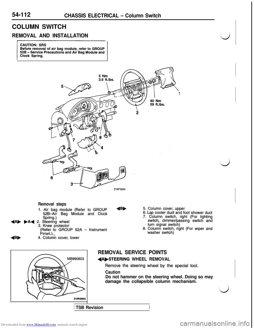
REMOVAL AND INSTALLATION
1
Removal steps
1. Air bag module (Refer to GROUP525Air Bag Module and ClockSpring.)+A, .A+ 2. Steering wheel3. Knee protector
4Bb
$F$i;)to GROUP 52A - Instrument
4. Column cover, lower
4B,5. Column cover, upper6. Lap cooler duct and foot shower duct7. Column switch, right (For lightingswitch, dimmer/passing switch andturn signal switch)8. Column switch, right (For wiper andwasher switch)
REMOVAL SERVICE POINTS
(A,STEERING WHEEL REMOVAL
Remove the steering wheel by the special tool.
Caution
Do not hammer on the steering wheel. Doing so may
damage the collapsible column mechanism.
1 TSB Revision
Page 609 of 738
Downloaded from www.Manualslib.com manuals search engine L
L
CHASSIS ELECTRICAL - Column Switch54-113
Front of vehicles
219FOlZ:
Mating mark-! !kU19FOOE
-
16FO237
16FO1:900002398
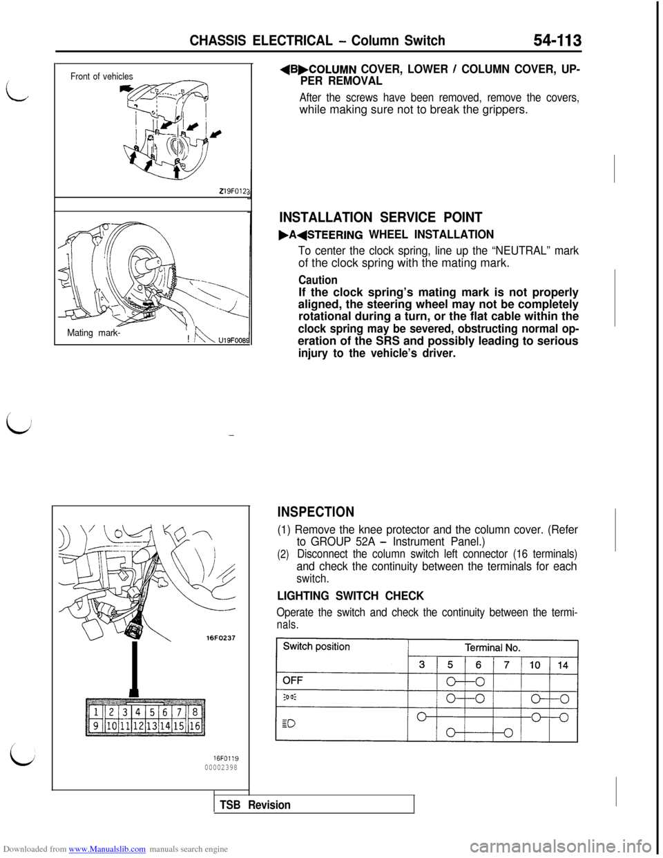
+B,COLUMN COVER, LOWER / COLUMN COVER, UP-
PER REMOVAL
After the screws have been removed, remove the covers,while making sure not to break the grippers.
INSTALLATION SERVICE POINT
.A(STEERING WHEEL INSTALLATION
To center the clock spring, line up the “NEUTRAL” markof the clock spring with the mating mark.
CautionIf the clock spring’s mating mark is not properly
aligned, the steering wheel may not be completely
rotational during a turn, or the flat cable within the
clock spring may be severed, obstructing normal op-eration of the SRS and possibly leading to serious
injury to the vehicle’s driver.
INSPECTION
(1) Remove the knee protector and the column cover. (Refer
(2)
to GROUP 52A - Instrument Panel.)
Disconnect the column switch left connector (16 terminals)
and check the continuity between the terminals for each
switch.
LIGHTING SWITCH CHECK
Operate the switch and check the continuity between the termi-
nals.
TSB Revision
Page 610 of 738
Downloaded from www.Manualslib.com manuals search engine 54-114CHASSIS ELECTRICAL - Column Switch
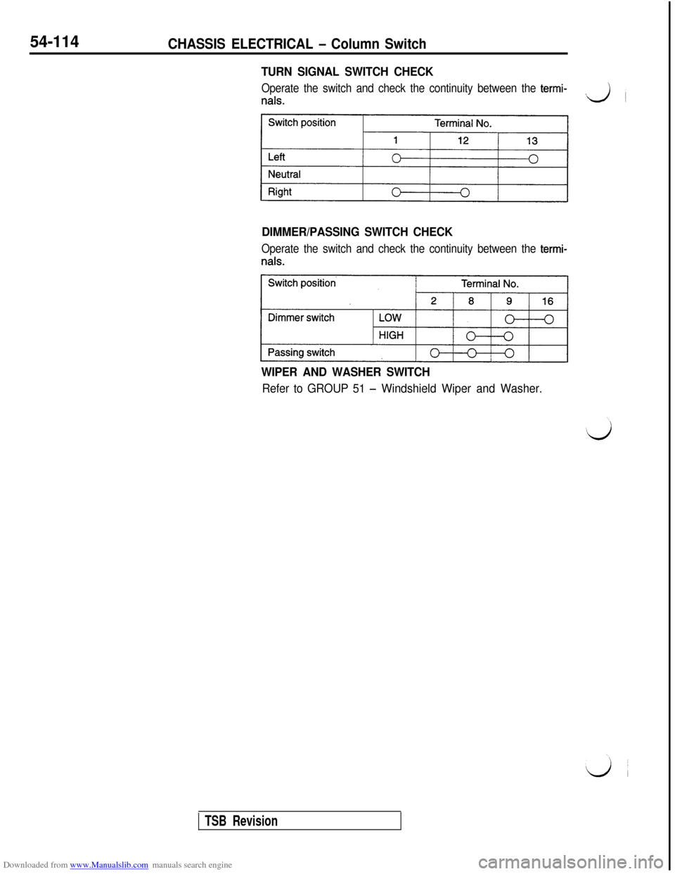
TURN SIGNAL SWITCH CHECK
Operate the switch and check the continuity between the termi-
nals.J
~
DIMMER/PASSING SWITCH CHECK
Operate the switch and check the continuity between the termi-
WIPER AND WASHER SWITCH
Refer to GROUP 51 - Windshield Wiper and Washer.
TSB Revision