diagram MITSUBISHI 3000GT 1994 2.G User Guide
[x] Cancel search | Manufacturer: MITSUBISHI, Model Year: 1994, Model line: 3000GT, Model: MITSUBISHI 3000GT 1994 2.GPages: 738, PDF Size: 35.06 MB
Page 43 of 738
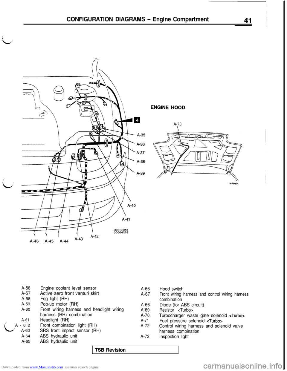
Downloaded from www.Manualslib.com manuals search engine CONFIGURATION DIAGRAMS - Engine CompartmentENGINE
HOOD
A-73
\
/I IIA-46 A-45 A-44
A-43A-42
A-56
A-57A-58
A-59
A-60
A-61A-62
A-63
A-64
A-65
Engine coolant level sensorActive aero front venturi skirt
Fog light (RH)
Pop-up motor (RH)
Front wiring harness and headlight wiring
harness (RH) combination
Headlight (RH)
Front combination light (RH)
SRS front impact sensor (RH)
ABS hydraulic unit
ABS hydraulic unit
A-66Hood switch
A-67
Front wiring harness and control wiring harness
combination
A-66
Diode (for ABS circuit)
A-69
Resistor
A-70
Turbocharger waste gate solenoid
A-71
Fuel pressure solenoid
A-72
Control wiring harness and solenoid valve
harness combination
A-73
Inspection light
TSB Revision
Page 44 of 738
Downloaded from www.Manualslib.com manuals search engine 42CONFIGURATION DIAGRAMS - Engine Compartment
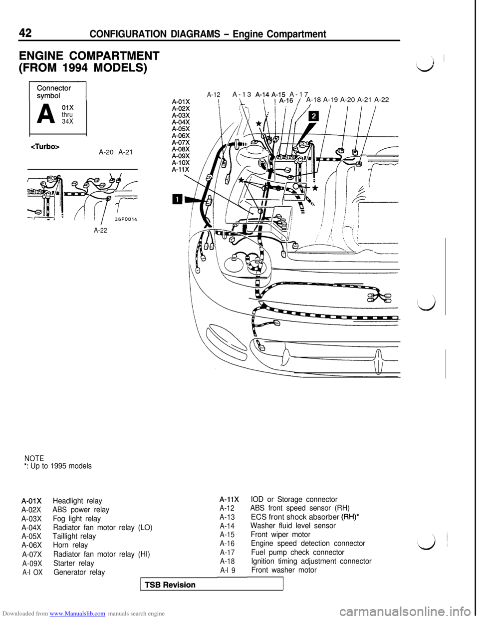
ENGINE COMPARTMENT
(FROM 1994 MODELS)
A01xthru
34X
A-22
NOTE*: Up to 1995 models
A-01X
A-02X
A-03X
A-04X
A-05X
A-06X
A-07X
A-09X
A-l OX
A-12A-13 A-14A-15 A-17A-01X!i\1 A-16 /A-18 A-19 A-20 A-21 A-22/I
Headlight relay
ABS power relay
Fog light relay
Radiator fan motor relay (LO)
Taillight relay
Horn relay
Radiator fan motor relay (HI)
Starter relay
Generator relayA-11XIOD or Storage connector
A-12ABS front speed sensor (RH)
A-13ECS front shock absorber (RH)*
A-14
Washer fluid level sensor
A-15Front wiper motor
A-16Engine speed detection connector
A-17Fuel pump check connector
A-18Ignition timing adjustment connector
A-l 9Front washer motorTSB
Revision
Page 45 of 738
Downloaded from www.Manualslib.com manuals search engine CONFIGURATION DIAGRAMS - Engine CompartmentA-23 A-24 A-25
A-26 A-27
i
L
A-30
A-31X
A-32XA-33X
tim-I
\; ,.,,,,/ /--fk!pJ / -
-_---__
jfy--@--o Id\ /
rilf+““1
=\
::-2II
36FOt2200004253
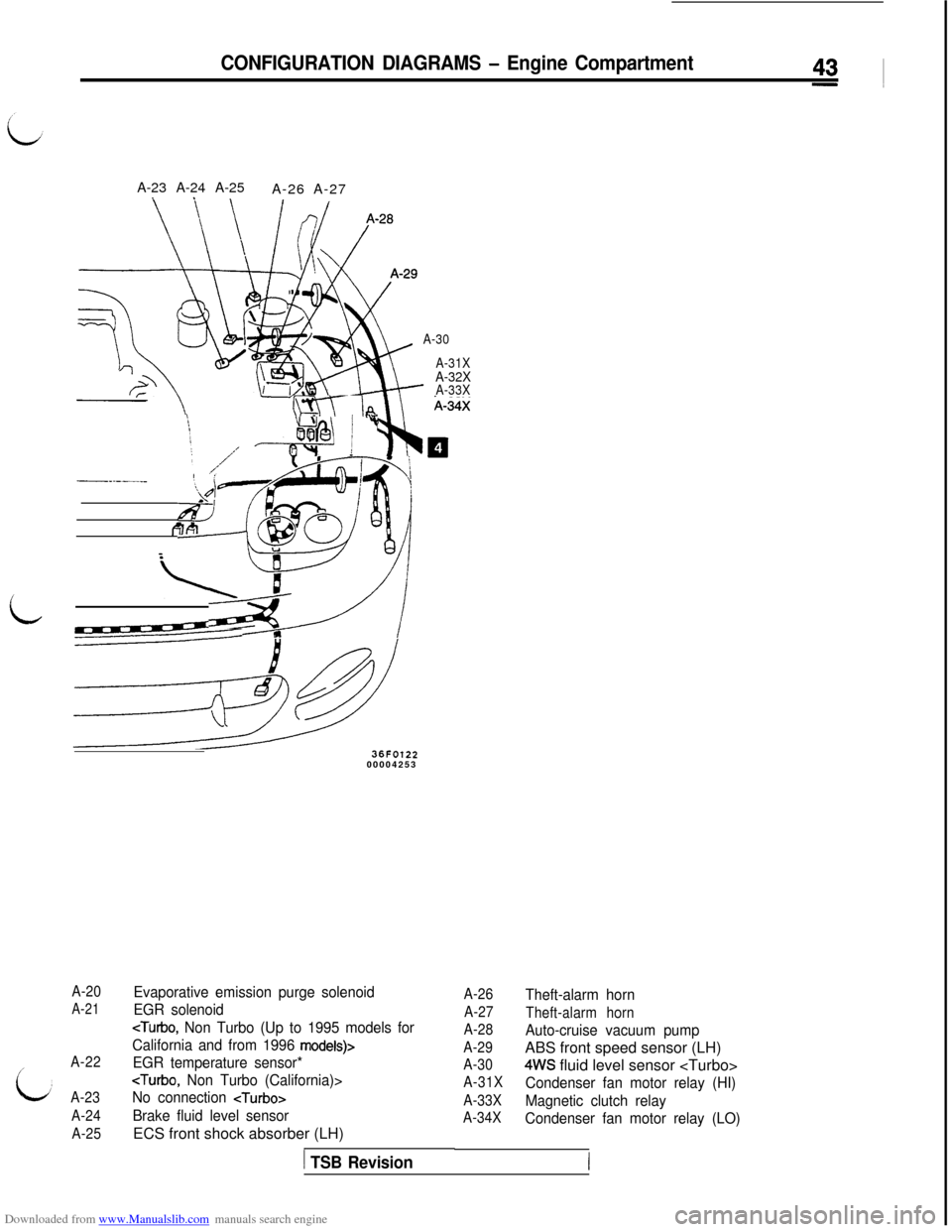
A-20
A-21
A-22
A-23
A-24
A-25
Evaporative emission purge solenoid
EGR solenoid
cTurbo, Non Turbo (Up to 1995 models for
California and from 1996
models)>
EGR temperature sensor*
No connection
Brake fluid level sensorECS front shock absorber (LH)
1 TSB Revision
A-26
A-27
A-28
A-29
A-30
A-31X
A-33X
A-34XTheft-alarm horn
Theft-alarm horn
Auto-cruise vacuum pumpABS front speed sensor (LH)
4WS fluid level sensor
Condenser fan motor relay (HI)
Magnetic clutch relay
Condenser fan motor relay (LO)
Page 46 of 738
Downloaded from www.Manualslib.com manuals search engine 44CONFIGURATION DIAGRAMS - Engine Compartment
Connector
symbol
A
35
thru
79
36FOOl4
A-72A-71A-67
:
A-64 --+py>
A-77\ \
A-49
A-50
NOTE*t: Up to 1995 models*2: From 1996 models
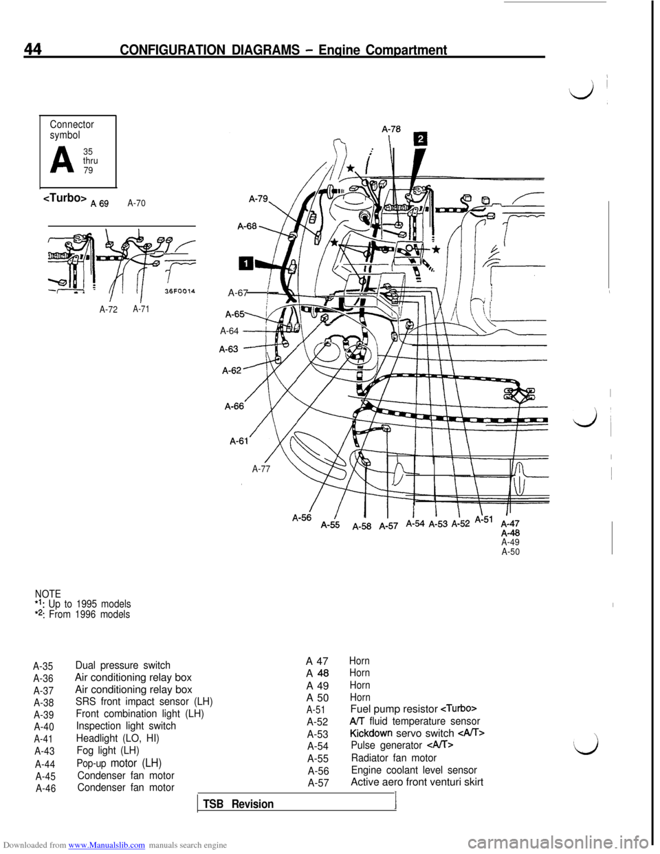
A-35
A-36
A-37
A-38
A-39
A-40
A-41
A-43
A-44
A-45
A-46
Dual pressure switchAir conditioning relay box
Air conditioning relay box
SRS front impact sensor (LH)
Front combination light (LH)
Inspection light switch
Headlight (LO, HI)
Fog light (LH)
Pop-up motor (LH)
Condenser fan motor
Condenser fan motor
TSB RevisionA 47
HornA
48HornA 49
HornA 50
Horn
A-51Fuel pump resistor
A-52AIT fluid temperature sensor
A-53
Kickdown servo switch
A-54Pulse generator CA/T>
A-55Radiator fan motor
A-56Engine coolant level sensor
A-57Active aero front venturi skirt
I
,
‘d ,
,
I
k&i
I1
I
Page 47 of 738
Downloaded from www.Manualslib.com manuals search engine CONFIGURATION DIAGRAMS - Engine Compartment45
; !i i\1 ._’ !\\-7’I \ ‘\
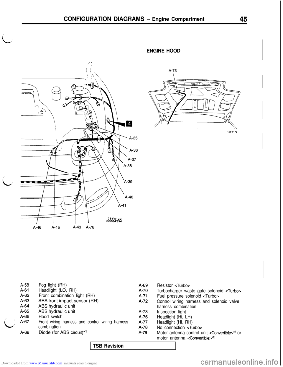
A-58
A-61A-62A-63A-64A-65A-66A-67A-66
A-46A-45A-43 A-76
Fog light (RH)
Headlight (LO, RH)
Front combination light (RH)
SRS front impact sensor (RH)
ABS hydraulic unit
ABS hydraulic unit
Hood switch
Front wiring harness and control wiring harness
combinationDiode (for ABS
circuit)*’
ENGINE HOOD
A-73A-69A-70
A-71A-72A-73A-76A-77A-78
A-79
Resistor
Turbocharger waste gate solenoid
Fuel pressure solenoid
Control wiring harness and solenoid valve
harness combination
Inspection light
Headlight (Hi, LH)
Headlight (HI, RH)
No connection
Motor antenna control unit cConvertible>*1 or
motor antenna
4onvertible>*2
TSB Revision
Page 48 of 738
Downloaded from www.Manualslib.com manuals search engine 46CONFIGURATION DIAGRAMS - Engine and Transaxle
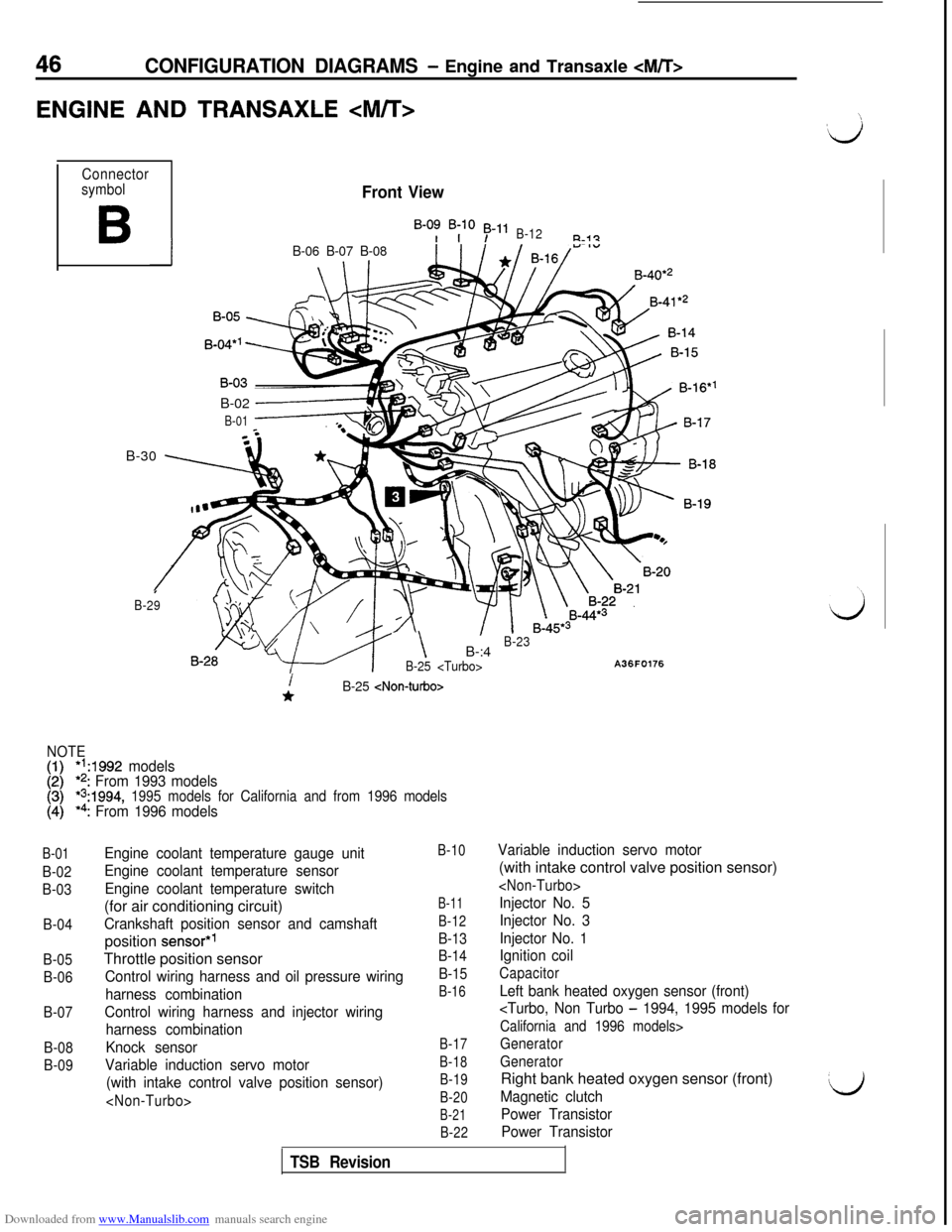
ENGINE AND TRANSAXLE
Connector
symbol
B
Front View
B-0: B;lO 53-11B-12R-i?
IB-06 B-07 B-08B-40*’
B-02
------+
B-01B-30
\ 7
I
B-29
- \B-:4B-23
B-25
A36F0176
B-01
B-02
B-03
B-04
B-05
B-06
B-07
B-08
B-09
i*B-25
NOTE
[:I*‘A992 models*2: From 1993 models*s:1994, 1995 models for California and from 1996 models*4: From 1996 models
Engine coolant temperature gauge unit
Engine coolant temperature sensor
Engine coolant temperature switch(for air conditioning circuit)
Crankshaft position sensor and camshaftposition
sensor*’Throttle position sensor
Control wiring harness and oil pressure wiring
harness combination
Control wiring harness and injector wiring
harness combination
Knock sensor
Variable induction servo motor
(with intake control valve position sensor)
B-10
B-11
B-12
B-13
B-14
B-15
B-16
B-17
B-18
B-19
B-20
B-21
B-22
Variable induction servo motor(with intake control valve position sensor)
Injector No. 5
Injector No. 3
Injector No. 1
Ignition coil
Capacitor
Left bank heated oxygen sensor (front)
California and 1996 models>
Generator
GeneratorRight bank heated oxygen sensor (front)
Magnetic clutch
Power Transistor
Power TransistorL)
TSB Revision
Page 49 of 738
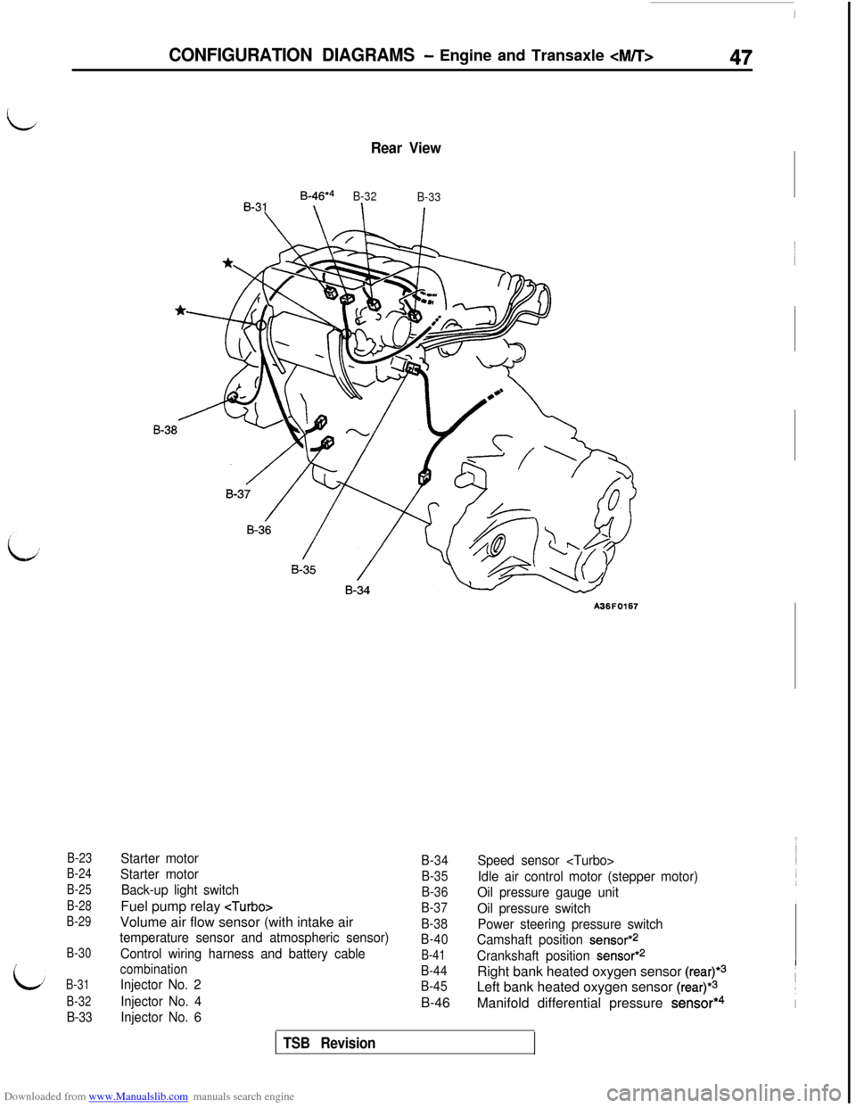
Downloaded from www.Manualslib.com manuals search engine B-23
B-24
B-25
B-28
B-29
B-30
B-31
B-32
B-33
Rear View
B-46*4
B-32
B-33
A36F0167
Starter motor
Starter motor
Back-up light switchFuel pump relay
temperature sensor and atmospheric sensor)
Control wiring harness and battery cable
combination
Injector No. 2
Injector No. 4
Injector No. 6
B-34
B-35
B-36
B-37
B-38
B-40
B-41
B-44
B-45B-46
Speed sensor
Idle air control motor (stepper motor)
Oil pressure gauge unit
Oil pressure switch
Power steering pressure switch
Camshaft position
sensor*2
Crankshaft position sensor*2Right bank heated oxygen sensor
(rear)*3Left bank heated oxygen sensor
(rear)*3Manifold differential pressure
sensor*4
CONFIGURATION DIAGRAMS - Engine and Transaxle
TSB Revision
Page 50 of 738
Downloaded from www.Manualslib.com manuals search engine 48CONFIGURATION DIAGRAMS - Ennine and Transaxle
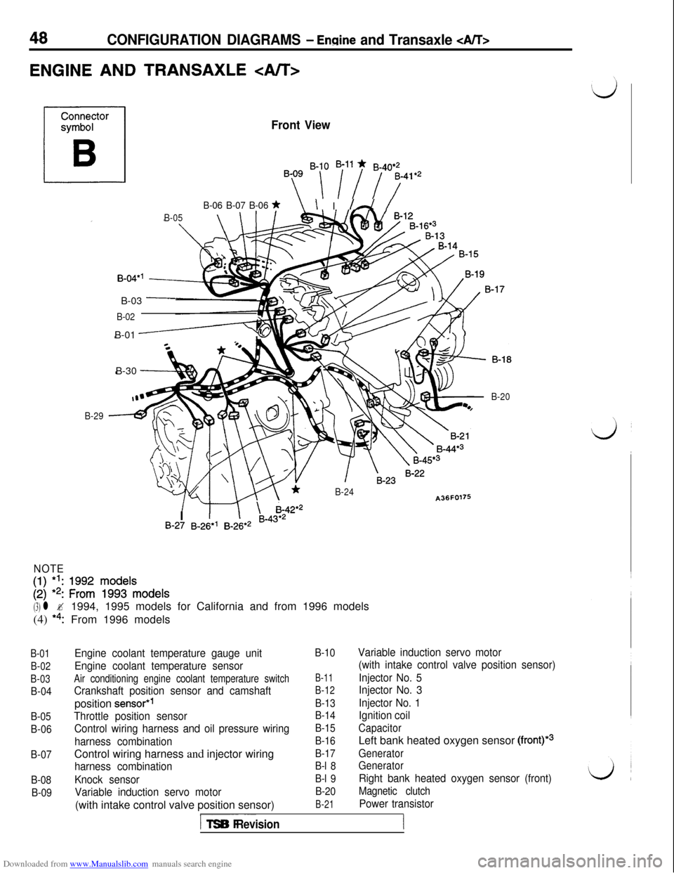
ENGINE AND TRANSAXLE
Front View
By ‘-[ i”i 7741e2
B-06 B-07 B-06 *\ I I /A /
B-05\ \IB-30
-
B-04*’B-03
-
B-02B-01
-
B-29
*B-24A36F0176
/ m \ i-42*2
B-20I
1IB-27 B-26*’ B-26*2 B-43*2
NOTE
[:I 1:: zif ~$$‘~ode~s
(3) l ?1994, 1995 models for California and from 1996 models
(4)
*4:From 1996 models
B-01
B-02
B-03
B-04
B-05
B-06
B-07
B-08
B-09
Engine coolant temperature gauge unit
Engine coolant temperature sensor
Air conditioning engine coolant temperature switch
Crankshaft position sensor and camshaftposition
sensor*’
Throttle position sensor
Control wiring harness and oil pressure wiring
harness combinationControl wiring harness and injector wiring
harness combination
Knock sensor
Variable induction servo motor(with intake control valve position sensor)
B-10
B-11
B-12
B-13
B-14
B-15
B-16
B-17
B-l 8
B-l 9
B-20
B-21
Variable induction servo motor
(with intake control valve position sensor)
Injector No. 5
Injector No. 3
Injector No. 1
Ignition coil
CapacitorLeft bank heated oxygen sensor
(front)*3
Generator
Generator
Right bank heated oxygen sensor (front)
Magnetic clutch
Power transistor
I-- ~~~TSB Revision
Page 51 of 738
Downloaded from www.Manualslib.com manuals search engine B-22
B-23
B-24
B-26
B-27
B-29
B-30
B-31
B-32
B-33
B-34
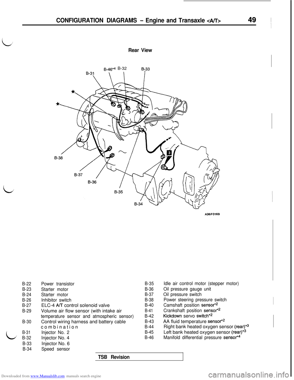
Rear View
B-46*4 B-328~33
CONFIGURATION DIAGRAMS - Engine and Transaxle 49 ~
I
A36F0169
Power transistor
Starter motor
Starter motor
Inhibitor switchELC-4
A/T control solenoid valve
Volume air flow sensor (with intake air
temperature sensor and atmospheric sensor)Control wiring harness and battery cable
combination
Injector No. 2Injector No. 4
Injector No. 6
Speed sensor
B-35
B-36
B-37
B-38
B-40
B-41
B-42
B-43
B-44
B-45
B-46
Idle air control motor (stepper motor)
Oil pressure gauge unit
Oil pressure switch
Power steering pressure switch
Camshaft position
sensor*2
Crankshaft position sensor*2
Kickdown servo switch*2AA fluid temperature
sensor*2Right bank heated oxygen sensor
(rear)*3Left bank heated oxygen sensor
(rear)*3
Manifold differential pressure sensor*4
TSB Revision
Page 52 of 738
Downloaded from www.Manualslib.com manuals search engine 50CONFIGURATION DIAGRAMS - Dash Panel
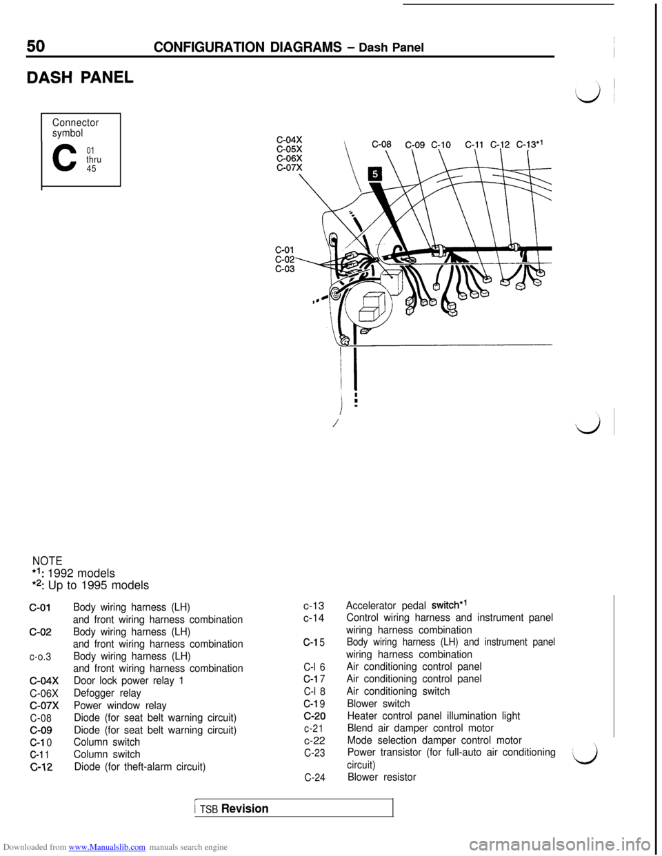
DASH PANEL
Connector
symbol
C
01thru
45
NOTE*I: 1992 models
*2: Up to 1995 models
c-01c-02
c-o.3
c-04x
C-06X
c-07x
C-08c-09
C-l 0
C-l 1
c-12
Body wiring harness (LH)
and front wiring harness combination
Body wiring harness (LH)
and front wiring harness combination
Body wiring harness (LH)
and front wiring harness combination
Door lock power relay 1
Defogger relay
Power window relay
Diode (for seat belt warning circuit)
Diode (for seat belt warning circuit)
Column switch
Column switch
Diode (for theft-alarm circuit)c-13
c-14
C-l 5
C-l 6
C-l 7
C-l 8
C-l 9c-20
c-21c-22
C-23
C-24
/ i
i
.m
/\\
LJ
Accelerator pedal switch*’
Control wiring harness and instrument panel
wiring harness combination
Body wiring harness (LH) and instrument panel
wiring harness combination
Air conditioning control panel
Air conditioning control panel
Air conditioning switch
Blower switch
Heater control panel illumination light
Blend air damper control motor
Mode selection damper control motor
Power transistor (for full-auto air conditioning
circuit)
Blower resistor
I TSB Revision