start MITSUBISHI 3000GT 1994 2.G Owner's Manual
[x] Cancel search | Manufacturer: MITSUBISHI, Model Year: 1994, Model line: 3000GT, Model: MITSUBISHI 3000GT 1994 2.GPages: 738, PDF Size: 35.06 MB
Page 378 of 738
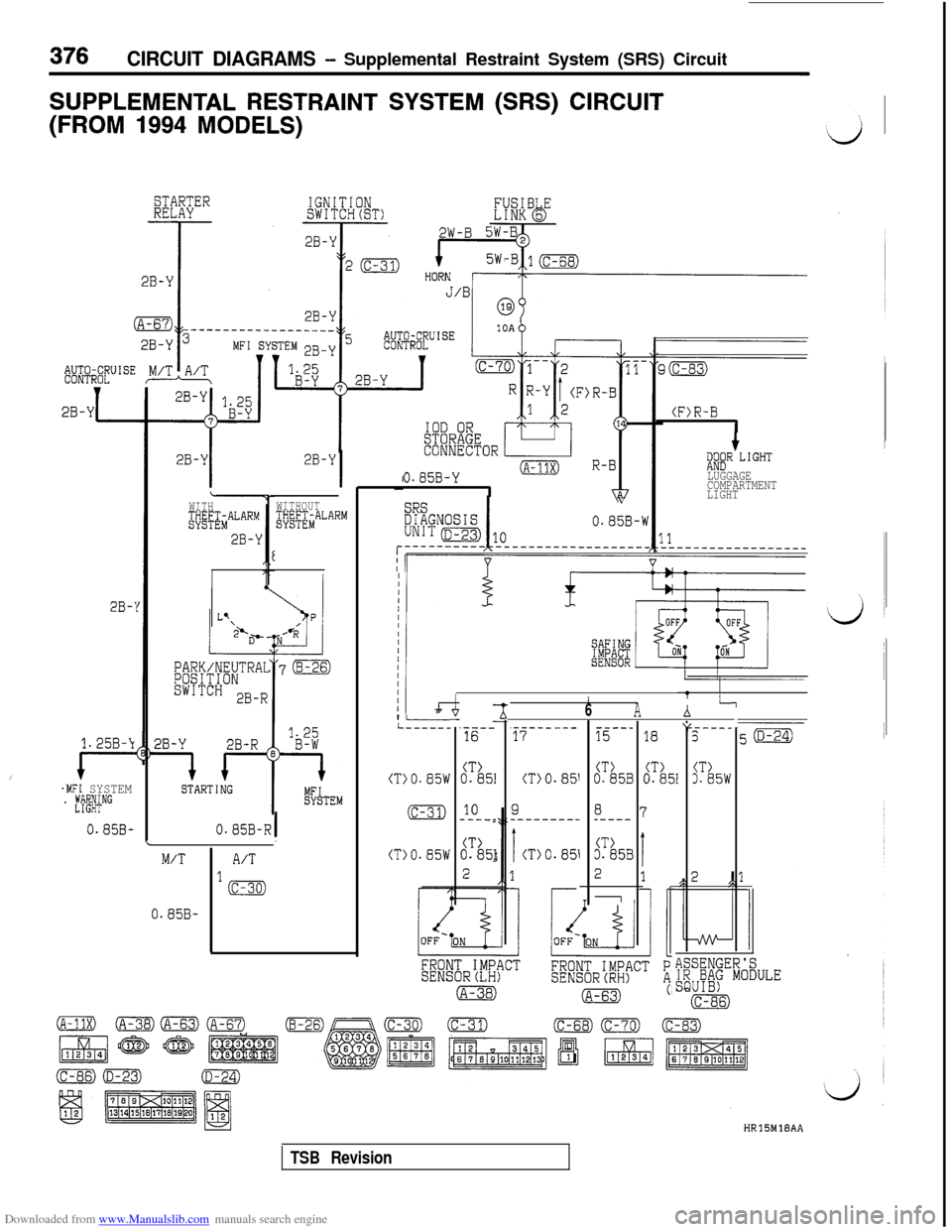
Downloaded from www.Manualslib.com manuals search engine 376CIRCUIT DIAGRAMS - Supplemental Restraint System (SRS) Circuit
SUPPLEMENTAL RESTRAINT SYSTEM (SRS) CIRCUIT
(FROM 1994 MODELS)
STARTERRELAY
.$##JISE
2B-Y
2B-Y
WITH@&ALARM
2B-Y
2B-Y
I
Ei8” L1GHTLUGGAGE
COMPARTMENT
LIGHT0.05B-Y(A-11X)
IWITHOUT$t/E&ALARMV0.85B-W
ILr4-I------.----16
2B-'
-t
CT)0.851
10-----
CT>0.851
2
//6Ai
----_5
CT)3.85W
7a.----- ---17
(TjO.851
9--------_
i(TjO.851
-----1518
CT)CT)0.85B0.851
8_----
CT>3.85B
2
Y
1.25B-\
/I----.MFI SYSTEM. Ef~#NG
0.85B-
(TlO.85W
(c-31)
0.85B-R!L(T)O.85WM/TA/T
lm-
FRONT IMPACTSENSORCLH)
(A-38)
0.85B-
ASSENGER'SIR BAG MODULESQUIB)(c-86)HRlSMlEAA
TSB Revision
Page 401 of 738
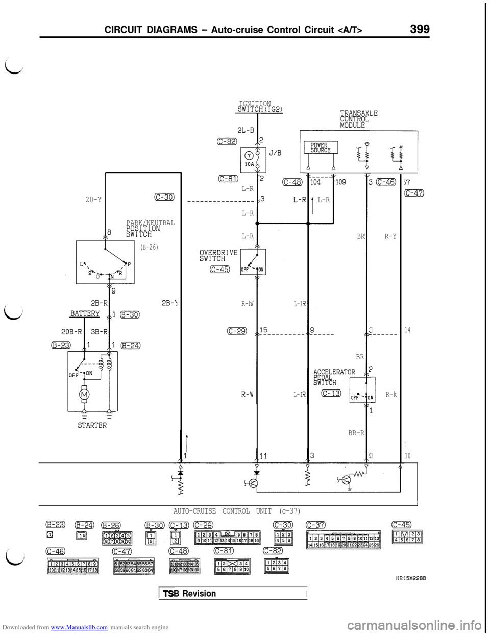
Downloaded from www.Manualslib.com manuals search engine CIRCUIT DIAGRAMS - Auto-cruise Control Circuit CA/T>399
IGNITIONSWITCH(IG2)
20-Y
(c-30)
PARK/NEUTRAL
8SP
;;sCWHON
(B-26)M
~
STARTERX
2B-\1
[c-81)
L-R
----------------
~~~~~~1""
(c-45)
L-R
L-R
R-h
(c-29)
R-b
L-l
15.----------
L-I
L-R
io9
BR
BR
BR-R
3m
R-Y
3.------
I
InR-k
1
3
j7
m
14
I
10
IAUTO-CRUISE CONTROL UNIT (c-37)
HR15M22BB
ITSB RevisionI
Page 405 of 738

20B-RI 3B-RI
2B-!
STARTER
L-R
:3I
L-R
IL-R6I\
R-h")
Downloaded from www.Manualslib.com manuals search engine CIRCUIT DIAGRAMS - Auto-cruise Control Circuit 403 ,
i
LJ
-If--L- “I
BATTERY 11 (B-30)
20B-RI 3B-RI
2B-!
STARTER
L-R
:3I
L-R
IL-R6I\
R-hI
1,:(c-29
R-W
5
15.--
11A‘
CE
-
i
---
L
---
L
-$[!W;tLE
MODULE
>-R
-
3-R
--
-R
----_04
1 L-R
R-!
R-!
57
14
/
.O
1
AUTO-CRUISE CONTROL UNIT (c-37)
(B-23)-(c-30)(c-45)
ElaI
/
i
(c-47)
HR15M23BB
TSB Revision
Page 413 of 738
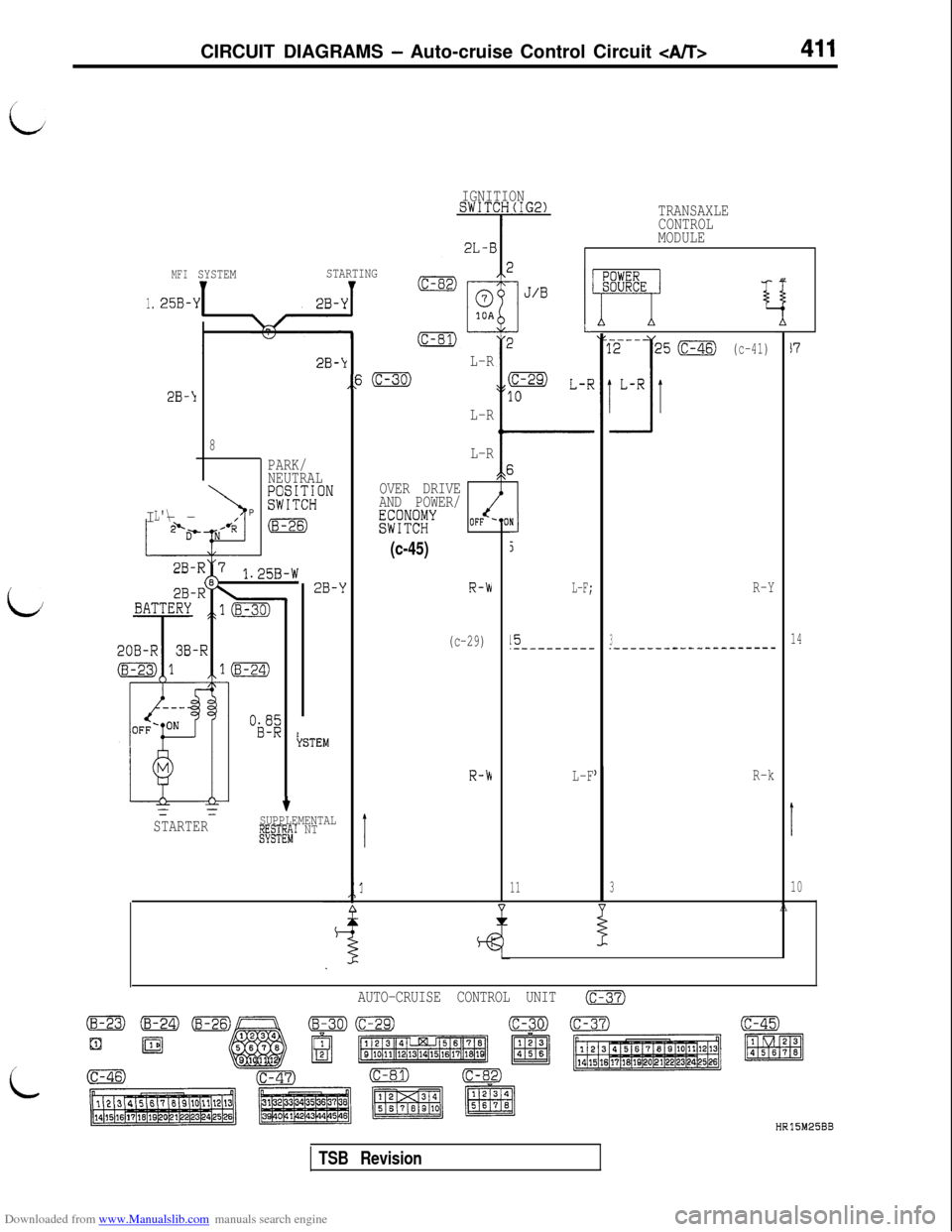
Downloaded from www.Manualslib.com manuals search engine CIRCUIT DIAGRAMS - Auto-cruise Control Circuit
IGNITIONSWITCH(IG2)TRANSAXLE
CONTROL
MODULE
MFI
25B-
SYSTEMSTARTING
I2B-k
,,s
-
(c-41)17L-R
(c-30)(c-es) L-R
10
L-R
L-R
c
OVER DRIVE
AND POWER/
EsR!EY!!J
(c-45)5
R-hL-F;R-Y
(c-29)15314.-_--_-----.--------------------
1.
R-hL-FR-k
I
11310I .$A
AUTO-CRUISE CONTROL UNIT(c-37)
2B-1I--
L'\
8
PARK/
NEUTRAL
;;sCI;;ON
\P(8-26)
i/2B-Y
.II'EM
tSUPPLEMENTALI?&~?;~' NTSTARTER
i
HR15M25BB
TSB Revision
Page 417 of 738
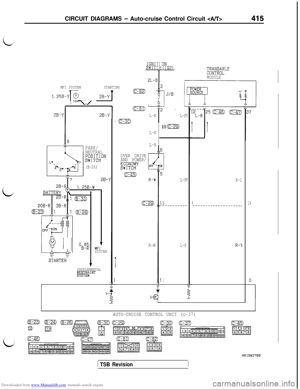
Downloaded from www.Manualslib.com manuals search engine CIRCUIT DIAGRAMS - Auto-cruise Control Circuit 415
IGNISwIT;;;;;;;LE
MODULE
TICH
2L-E
MFI SYSTEMSTARTING
1.25B-YT \-/ 28-Y/
(c-82)
E
(c-81)-
L-R
;m1
T _l-
L-F2B-k
IE
14
2B-\I
1PARK/
NEUTRAL
!W;~ON
(B-26)
2B-110
(C-29)
L-R
L-R
T
3
hP
,Lq
‘P-o- NH’RT---J
OVER DRIVE
AND POWER/
EK!'
5
L-F
5
:~---------
L-F
1
(c-45)
R-b
(c-29)
R-l
i-------------_______
L
1 Q I 1 “&1 L&
S;ARTER=
tMFISYSTEM
ISUPPLEMENTAL~"y@!!INT
R-WR-Y
t
L
AUTO-CRUISE CONTROL UNIT (c-37)
i
HR15M37BB
1 TSB Revision
Page 433 of 738
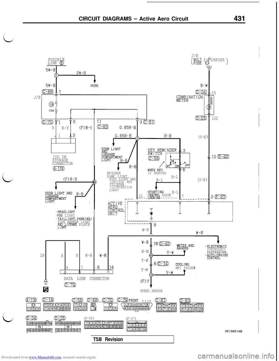
Downloaded from www.Manualslib.com manuals search engine CIRCUIT DIAGRAMS - Active Aero Circuit431
FUSIB E
LINK 6b
J/B
i
@
10A
\,----(c-70)‘1 “2.
RR-Y(F)R-I
,\ 1,.2
IOD ORSTORAGE
CONNECTOR
(F)R-Br
'HEADLIGHT.FOG LIGHT'TAILLIGHTsPARKING,SIDE MARKER LIGHTtjW&ICENSE PLATE
J/B
(WE 'e
BUZZERIS REMOVEDDOME LIGHT.FOOT LIGHT ANDB-L
IGNITION KEYB-LCYLINDER10ILLUMINATIONLIGHT
.STARTINGB-L10jf#Pf~~ DOOR7r--- ----------------------_-
(Y-B
(Y-B
JRPOSE)
59
?jc
I
102
20
-----I/
LL--------19W-R1
.
I.ELECTRONIC
CONTROLNICSUSPENSION
W-R
Y-W
Y-W
MFI SYSTEM
2BBBR-B
451AA*
nDATA LINK CONNECTOR(F>Y
n
(c-79)
SPEED SENSOR
(A-11X)0(c-58) (c-68) 0773 OFRONT SIDE (c-81)(c-83)
(D-42)
(F-27)
HR15M31AB
TSB Revision
Page 447 of 738
Downloaded from www.Manualslib.com manuals search engine 16-1
id
ENGINE
ELECTRICALCONTENTS
i;
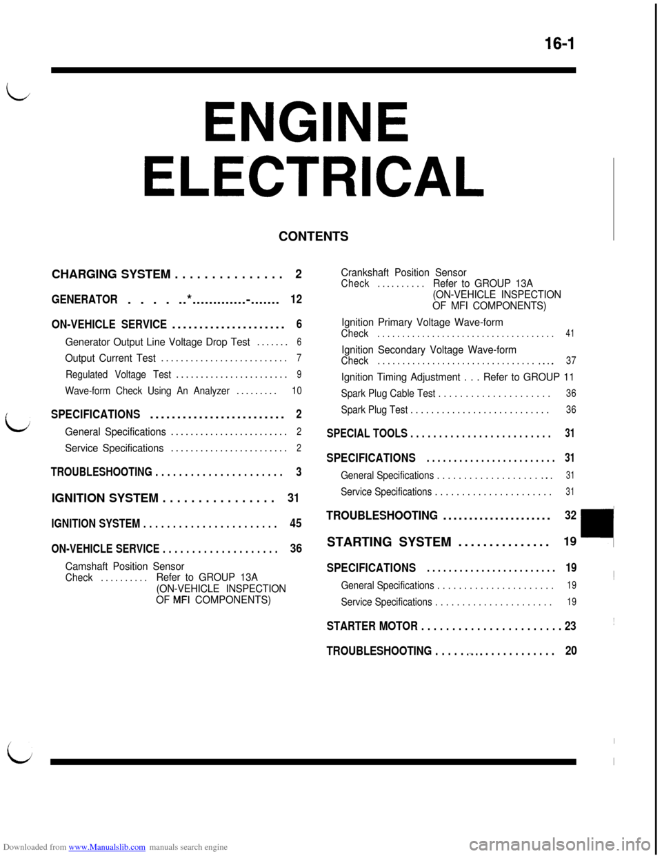
CHARGING SYSTEM . . . . . . . . . . . . . . .2
GENERATOR. . . . ..*.............-.......12
ON-VEHICLE SERVICE.....................
6
Generator Output Line Voltage Drop Test.......6
Output Current Test..........................7
Regulated Voltage Test.......................9
Wave-form Check Using An Analyzer.........10
SPECIFICATIONS.........................2
General Specifications........................2
Service Specifications........................2
TROUBLESHOOTING . . . . . . . . . . . . . . . . . . . . . .3
IGNITION SYSTEM . . . . . . . . . . . . . . . .31
IGNITION SYSTEM . . . . . . . . . . . . . . . . . . . . . . .45
ON-VEHICLE SERVICE . . . . . . . . . . . . . . . . . . . .36
Camshaft Position Sensor
Check. . . . . . . . . .Refer to GROUP 13A
(ON-VEHICLE INSPECTION
OF
MFI COMPONENTS)Crankshaft Position Sensor
Check. . _ . . . . . . .Refer to GROUP 13A
(ON-VEHICLE INSPECTION
OF MFI COMPONENTS)
Ignition Primary Voltage Wave-form
Check. . . . . . . . . . . . . . . . . . . . . . . . . . . . . . . . . . . .41
Ignition Secondary Voltage Wave-form
Check. . . . . . . . . . . . . . . . . . . . . . . . . . . . . . . . .._.37
Ignition Timing Adjustment . . . Refer to GROUP 11
Spark Plug Cable Test . . . . . . . . . . . . . . . . . . . . .36
Spark Plug Test . . . . . . . . . . . . . . . . . . . . . . . . . . .36
SPECIAL TOOLS . . . . . . . . . . . . . . . . . . . . . . . . .31
SPECIFICATIONS. . . . . . . . . . . . . . . . . . . . . . . .31
General Specifications . . . . . . . . . . . . . . . . . . . *. .31
Service Specifications . . . . . . . . . . . . . . . . . . . . . .31
TROUBLESHOOTING.....................32STARTING SYSTEM...............
19
SPECIFICATIONS. . . . . . . . . . . . . . . . . . . . . . . .19~
General Specifications . . . . . . . . . . . . . . . . . . . . . .19
Service Specifications . . . . . . . . . . . . . . . . . . . . . .19
STARTER MOTOR . . . . . . . . . . . . . . . . . . . . . . . 23~
TROUBLESHOOTING . . . . . .-a.. . . . . . . . . . . . .20
L
I
I
Page 451 of 738
Downloaded from www.Manualslib.com manuals search engine ENGINE ELECTRICAL - Charging System16-5
OPERATION
When engine is stoppedWhen the ignition switch is switched to the “ON”
position, electricity flows from the
‘I” terminal of
the generator to the field coil, and at the same time
the charging warning light illuminates.
When engine is being started/has started
When the engine is started, charging voltage is ap-
plied to the ‘I” terminal of the generator, with the
result that the charging warning light is extinguished.
In addition, because battery voltage is applied to
the “S” terminal of the generator, this battery voltage
is monitored at the
IC voltage regulator, thus switch-ing ON and OFF the current to the field coil and
thereby controlling the output voltage of the genera-
tor.
Power is supplied to each load from the “B” terminal
of the generator.
NOTE
The generator relay functions as a back-up for the
flow of electricity to the field coil if there is a discon-
nection or damaged wiring of the charging warning
light.
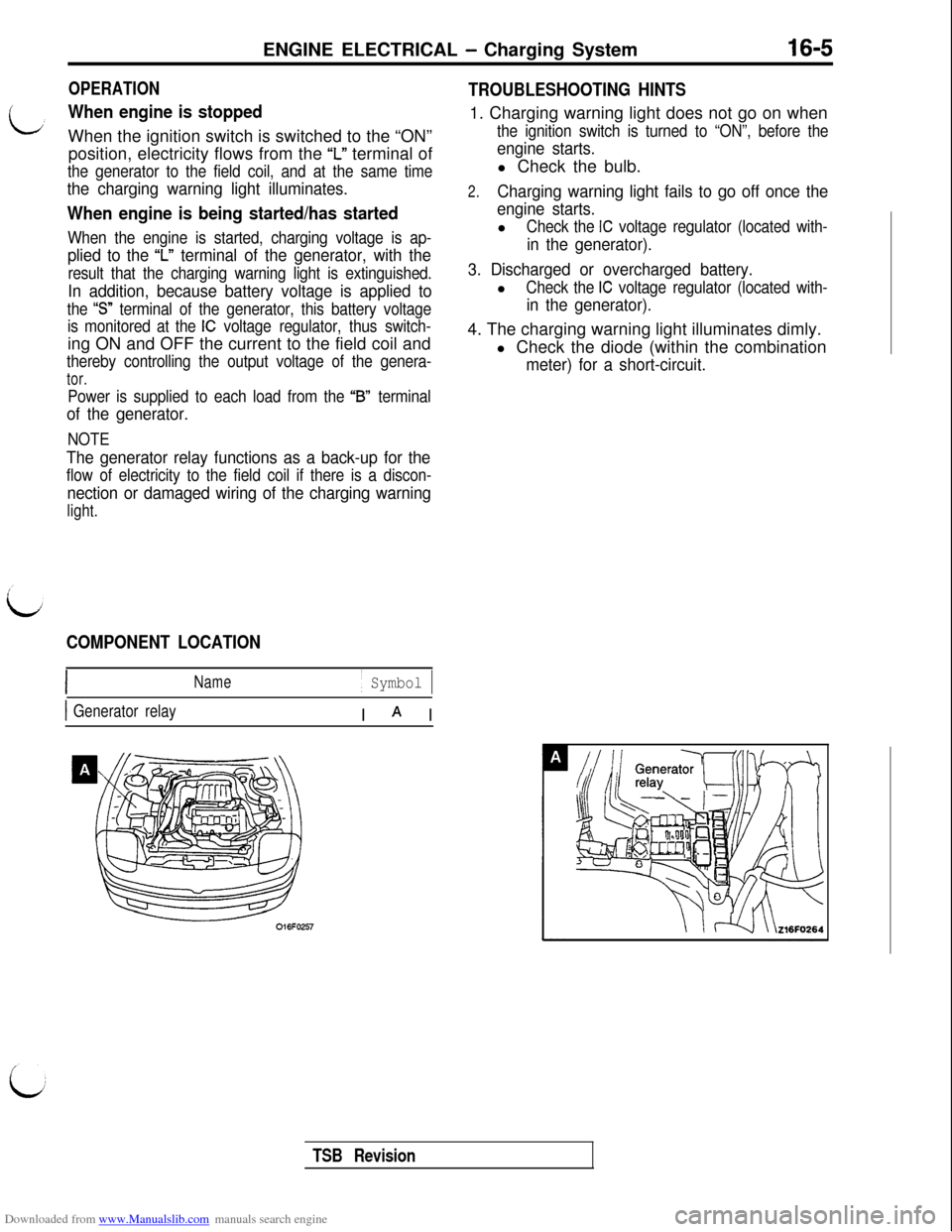
COMPONENT LOCATION
Name/ Symbol 1
1 Generator relayI A I
TROUBLESHOOTING HINTS1. Charging warning light does not go on when
the ignition switch is turned to “ON”, before the
engine starts.l Check the bulb.
2.Charging warning light fails to go off once the
engine starts.l
Check the IC voltage regulator (located with-
in the generator).
3. Discharged or overcharged battery.l
Check the IC voltage regulator (located with-
in the generator).4. The charging warning light illuminates dimly.
l Check the diode (within the combination
meter) for a short-circuit.
TSB Revision
Page 453 of 738
Downloaded from www.Manualslib.com manuals search engine ENGINE ELECTRICAL - Charging System16-7/
L
(6) Connect a tachometer. (For the procedure for
connecting the tachometer, refer to GROUP
- On-vehicle Service.)(7)
kkconnect the negative battery cable.
(8) Leave the hood open.
(9) Start the engine.
(lO)With the engine running at 2500 rpm, turn the
headlights and other lights on and off to adjust
the generator load so that the value displayed
on the ammeter is slightly above 30A.Limit value: Max. 0.3 V
NOTE
When the generator output is high and the value
displayed on the ammeter does not decreaseto
30A, set the value to 40A. Read the value
displayed on the voltmeter at this time.
In this case the limit value becomes max. 0.4V.
Adjust the engine speed by gradually decreas-
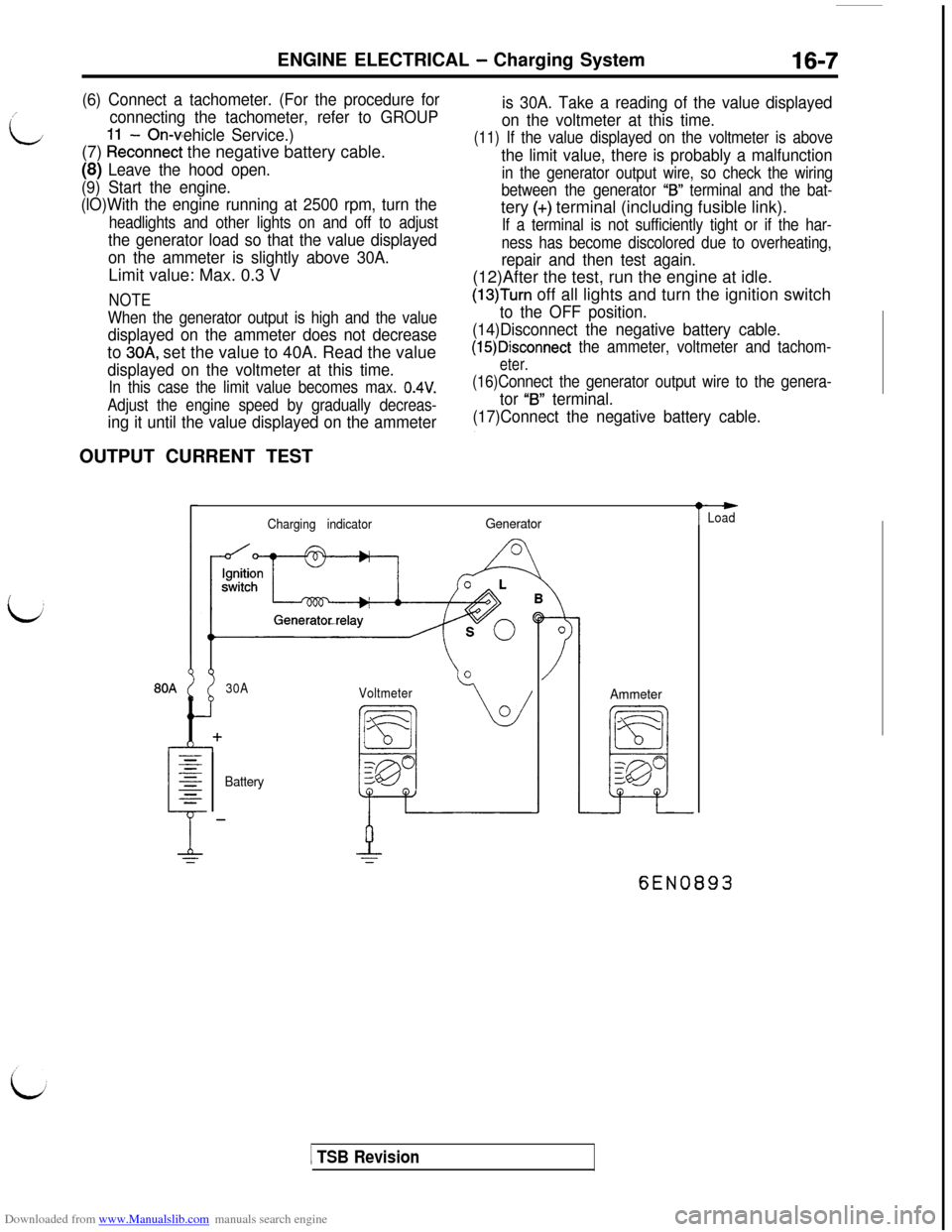
ing it until the value displayed on the ammeterOUTPUT CURRENT TEST
is 30A. Take a reading of the value displayed
on the voltmeter at this time.
(11) If the value displayed on the voltmeter is above
the limit value, there is probably a malfunction
in the generator output wire, so check the wiring
between the generator
“IS” terminal and the bat-tery
(+) terminal (including fusible link).
If a terminal is not sufficiently tight or if the har-
ness has become discolored due to overheating,
repair and then test again.(12)After the test, run the engine at idle.
(13)Turn off all lights and turn the ignition switch
to the OFF position.
(14)Disconnect the negative battery cable.
(15)Disconnect the ammeter, voltmeter and tachom-
eter.
(16)Connect the generator output wire to the genera-
tor “B” terminal.
(17)Connect the negative battery cable.
Charging indicatorGenerator
30A
Voltmeter
BatteryAmmeter
t
-Load
6EN0893
1 TSB Revision
Page 454 of 738
Downloaded from www.Manualslib.com manuals search engine 16-8ENGINE ELECTRICAL - Charging System
This test determines whether the generator outputs
normal current.(1) Before the test, always be sure to check the
following.l Generator installation
l
Battery (Refer to GROUP 54 - Battery.)
NOTE
The battery to be used should be slightly dis-charged. The load in a fully-charged battery
will be insufficient and the test may not be able
to be carried out correctly.l Generator drive belt tension (Refer to
GROUP 11- On-vehicle Service.)l Fusible link
l Abnormal noise from the generator while
the engine is running(2) Turn the ignition switch to the OFF position.
(3) Disconnect the negative battery cable.
(4) Disconnect the generator output wire from the
generator
“B” terminal and connect a DC testammeter with a range of O-100 A in series
between the “B” terminal and the disconnected
output wire. (Connect the
(+) lead of the amme-ter to the
“B” terminal, and then connect the(-) lead of the ammeter to the disconnected
output wire.)
Caution
Never use clips but tighten bolts and nutsto connect the line.
Otherwise loose
connections (e.g. using clips) will lead to
a serious accident because of high current.
NOTE
A clamp-type ammeter which enables measure-
ments to be taken without disconnecting the
generator output wire is recommended.(5) Connect a voltmeter with a range of 0
- 20
V between the generator “B” terminal and the
ground. (Connect the
(+) lead of the voltmeterto the “B” terminal, and then connect the (-)
lead of the voltmeter to the ground.)
(6) Connect a tachometer. (For the procedure forconnecting the tachometer, refer to GROUP
11 - On-vehicle Service.)
(7) Connect the negative battery cable.
(8) Leave the hood open.(9) Check to be sure that the reading on the
voltmeter is equal to the battery voltage.
NOTE
If the voltage is 0 V, the cause is probably an
open circuit in the wire or fusible link between
the generator “B” terminal and the battery
(+)
terminal.
(1O)After turning the light switch on and turning on
the headlights, start the engine.
(1l)lmmediately after setting the headlights to high
beam and turning the heater blower switch to
the high revolution position, increase the enginespeed to 2,500
r/min and read the maximum
current output value displayed on the ammeter.
Limit value: 70% of nominal current output
NOTEl
For the nominal current output, refer to the
Generator Specifications.l
Because the current from the battery will
soon drop after the engine is started, the
above step should be carried out as quickly
as possible in order to obtain the maximum
current output value.l The current output value will depend on
the electrical load and the temperature of
the generator body.l
If the electrical load is small while testing,the specified level of current may not be
output even though the generator is normal.
In such cases, increase the electrical load
by leaving the headlights turned on for sometime to discharge the battery or by using
the lighting system in another vehicle, and
then test again.l
The specified level of current also may not
be output if the temperature of the generator
body or the ambient temperature is too high.
In such cases, cool the generator and then
test again.
(12)The reading on the ammeter should be above
the limit value. If the reading is below the limit
value and the generator output wire is normal,
remove the generator from the engine and check
the generator.(13)Run the engine at idle speed after the test.
(14)Turn the ignition switch to the OFF position.
(15)Disconnect the negative battery cable.
(16)Disconnect the ammeter, voltmeter and
tachometer.(17)Connect the generator output wire to the
generator “B” terminal.
(18)Connect the negative battery cable.
TSB Revision