start MITSUBISHI 3000GT 1994 2.G Service Manual
[x] Cancel search | Manufacturer: MITSUBISHI, Model Year: 1994, Model line: 3000GT, Model: MITSUBISHI 3000GT 1994 2.GPages: 738, PDF Size: 35.06 MB
Page 474 of 738
Downloaded from www.Manualslib.com manuals search engine 16-28ENGINE ELECTRICAL - Starting System
Stop ringZ6EL0097
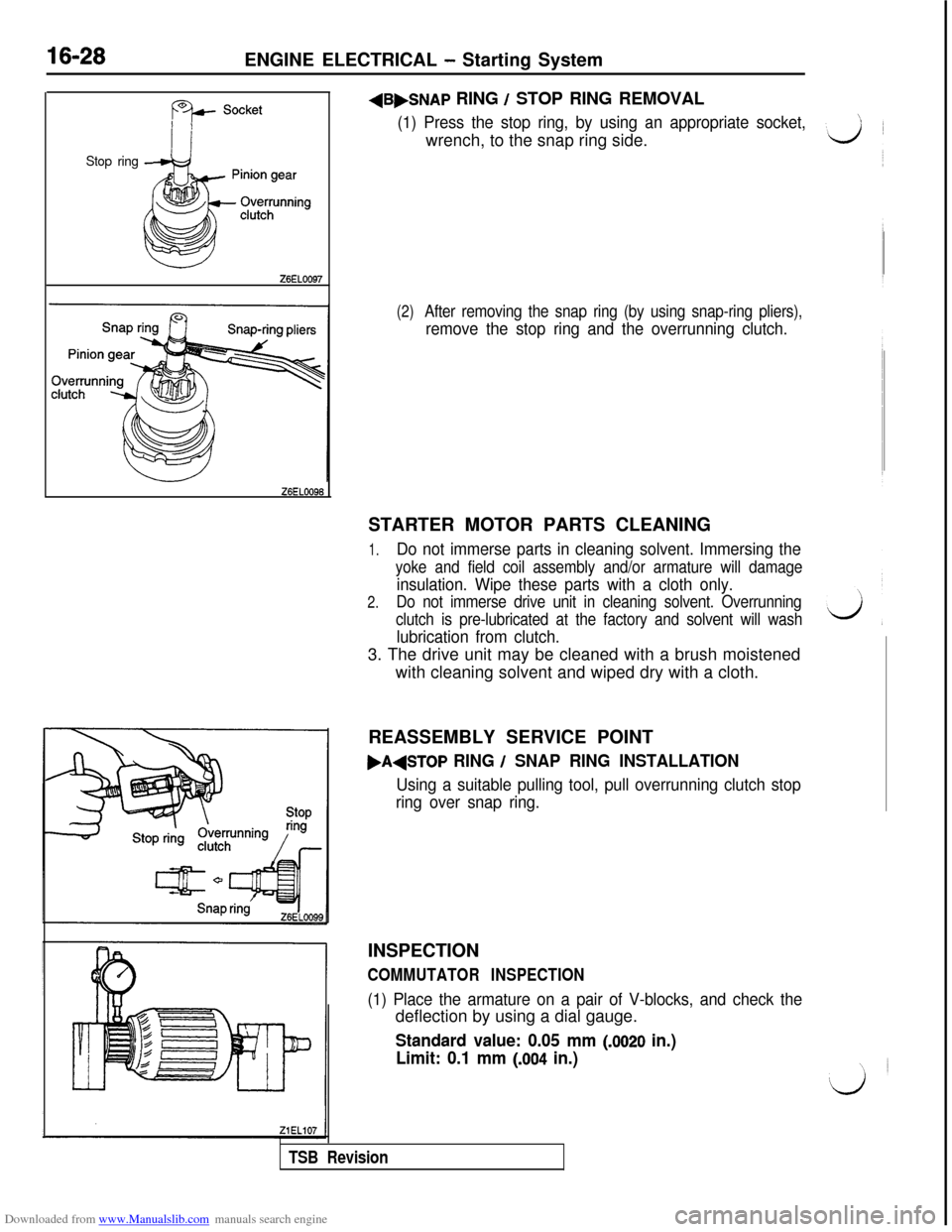
Z6ELOO96+B,SNAP
RING / STOP RING REMOVAL
(1) Press the stop ring, by using an appropriate socket,wrench, to the snap ring side.
(2)After removing the snap ring (by using snap-ring pliers),
remove the stop ring and the overrunning clutch.STARTER MOTOR PARTS CLEANING
1.Do not immerse parts in cleaning solvent. Immersing the
yoke and field coil assembly and/or armature will damage
insulation. Wipe these parts with a cloth only.
2.Do not immerse drive unit in cleaning solvent. Overrunning
clutch is pre-lubricated at the factory and solvent will wash
lubrication from clutch.3. The drive unit may be cleaned with a brush moistened
with cleaning solvent and wiped dry with a cloth.
REASSEMBLY SERVICE POINT
,A+TOP RING / SNAP RING INSTALLATION
Using a suitable pulling tool, pull overrunning clutch stop
ring over snap ring.INSPECTION
COMMUTATOR INSPECTION
(1) Place the armature on a pair of V-blocks, and check thedeflection by using a dial gauge.
Standard value: 0.05 mm (JO20 in.)
Limit: 0.1 mm
(.004 in.)
TSB Revision
Page 475 of 738
Downloaded from www.Manualslib.com manuals search engine ENGINE ELECTRICAL - Starting System16-29
ZiELllS
UndercutI
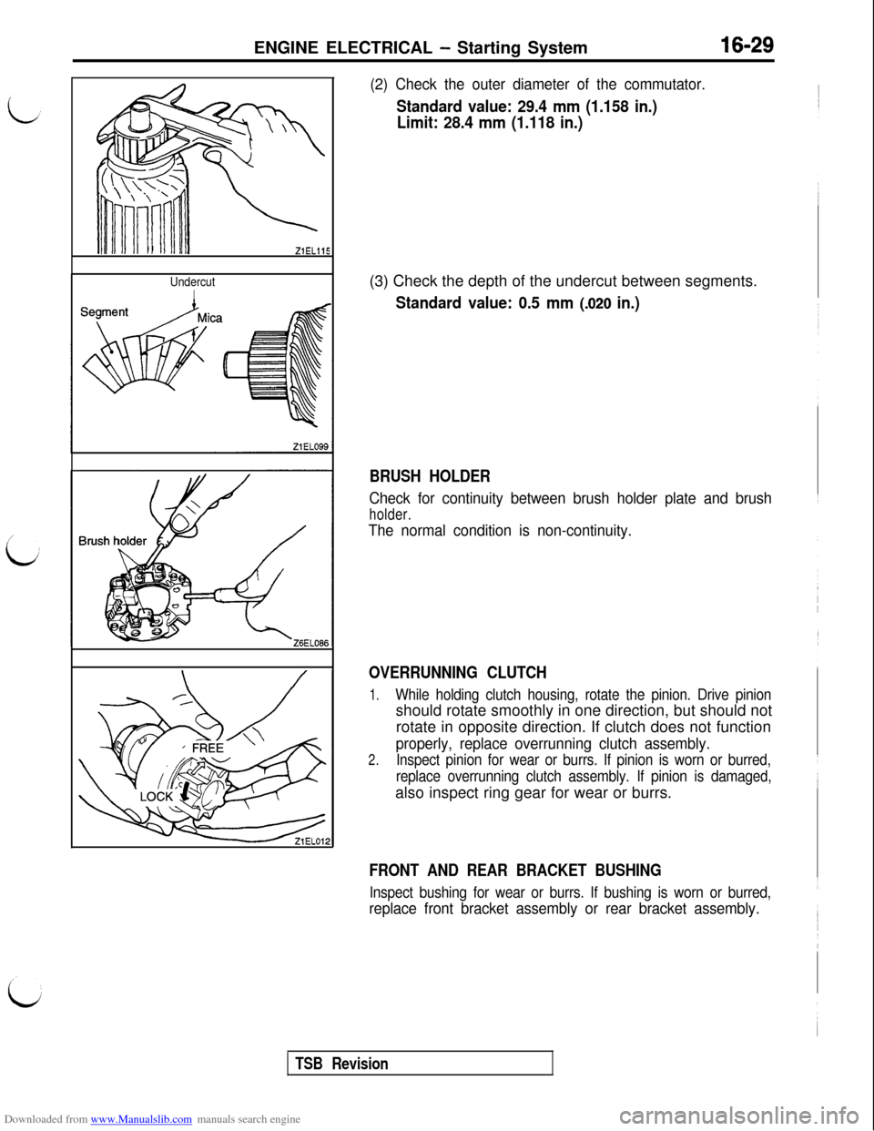
(2) Check the outer diameter of the commutator.
Standard value: 29.4 mm (1.158 in.)
Limit: 28.4 mm (1.118 in.)(3) Check the depth of the undercut between segments.
Standard value: 0.5 mm (.020 in.)
BRUSH HOLDER
Check for continuity between brush holder plate and brush
holder.
The normal condition is non-continuity.
OVERRUNNING CLUTCH
1.While holding clutch housing, rotate the pinion. Drive pinionshould rotate smoothly in one direction, but should not
rotate in opposite direction. If clutch does not function
properly, replace overrunning clutch assembly.
2.Inspect pinion for wear or burrs. If pinion is worn or burred,
replace overrunning clutch assembly. If pinion is damaged,also inspect ring gear for wear or burrs.
FRONT AND REAR BRACKET BUSHING
Inspect bushing for wear or burrs. If bushing is worn or burred,
replace front bracket assembly or rear bracket assembly.
TSB Revision
Page 476 of 738
Downloaded from www.Manualslib.com manuals search engine 16-30ENGINE ELECTRICAL - Starting System
Eq
C-- Wear limit line
-
New brush
Soldered
(Make sure that
there is no
excess solder on
brush surface)
Surface
Amarked
Zl EL049
GrowlerBRUSHES AND SPRINGS REPLACEMENT
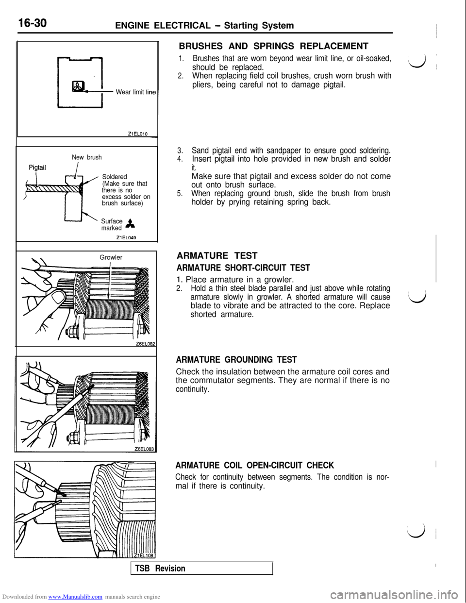
1.Brushes that are worn beyond wear limit line, or oil-soaked,
should be replaced.do
2.When replacing field coil brushes, crush worn brush with
pliers, being careful not to damage pigtail.
3.
4.Sand pigtail end with sandpaper to ensure good soldering.
Insert pigtail into hole provided in new brush and solder
it.Make sure that pigtail and excess solder do not come
out onto brush surface.
5.When replacing ground brush, slide the brush from brush
holder by prying retaining spring back.ARMATURE TEST
ARMATURE SHORT-CIRCUIT TEST
1. Place armature in a growler.
2.Hold a thin steel blade parallel and just above while rotating
armature slowly in growler. A shorted armature will causeblade to vibrate and be attracted to the core. Replace
shorted armature.
ARMATURE GROUNDING TESTCheck the insulation between the armature coil cores and
the commutator segments. They are normal if there is no
continuity.
ARMATURE COIL OPEN-CIRCUIT CHECK
Check for continuity between segments. The condition is nor-
mal if there is continuity.
TSB Revision
Page 481 of 738
Downloaded from www.Manualslib.com manuals search engine i;ENGINE ELECTRICAL
- Ignition System16-35
OPERATIONl
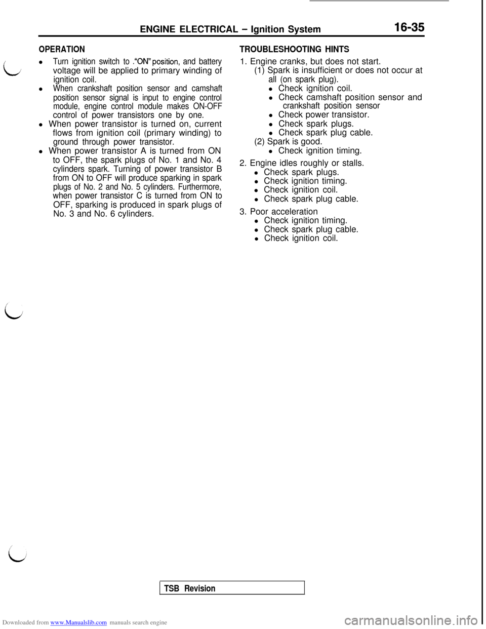
Turn ignition switch to .“ON”position, and batteryvoltage will be applied to primary winding of
ignition coil.l
When crankshaft position sensor and camshaft
position sensor signal is input to engine control
module, engine control module makes ON-OFF
control of power transistors one by one.l When power transistor is turned on, current
flows from ignition coil (primary winding) to
ground through power transistor.l When power transistor A is turned from ON
to OFF, the spark plugs of No. 1 and No. 4
cylinders spark. Turning of power transistor B
from ON to OFF will produce sparking in spark
plugs of No. 2 and No. 5 cylinders. Furthermore,
when power transistor C is turned from ON toOFF, sparking is produced in spark plugs of
No. 3 and No. 6 cylinders.
TROUBLESHOOTING HINTS1. Engine cranks, but does not start.
(1) Spark is insufficient or does not occur at
all (on spark plug).l Check ignition coil.
l Check camshaft position sensor and
crankshaft position sensorl Check power transistor.
l Check spark plugs.
l Check spark plug cable.
(2) Spark is good.
l Check ignition timing.
2. Engine idles roughly or stalls.
l Check spark plugs.
l Check ignition timing.
l Check ignition coil.
l Check spark plug cable.
3. Poor acceleration
l Check ignition timing.
l Check spark plug cable.
l Check ignition coil.
TSB Revision
Page 504 of 738
Downloaded from www.Manualslib.com manuals search engine 54-8CHASSIS ELECTRICAL - Ignition Switch
216AO57000002296INSPECTION
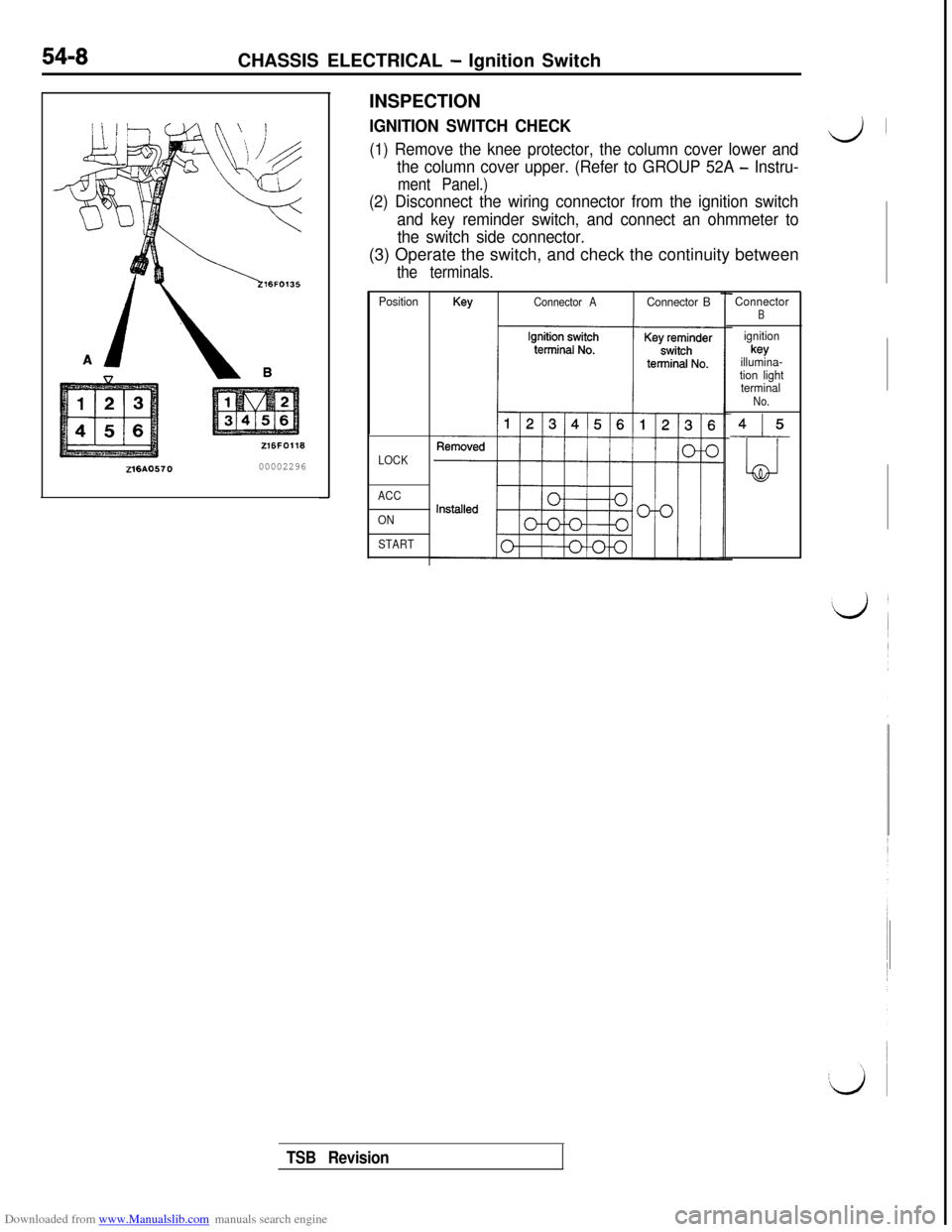
IGNITION SWITCH CHECK
(1) Remove the knee protector, the column cover lower andd’
the column cover upper. (Refer to GROUP 52A - Instru-
ment Panel.)
(2) Disconnect the wiring connector from the ignition switch
and key reminder switch, and connect an ohmmeter to
the switch side connector.(3) Operate the switch, and check the continuity between
the terminals.
PositionKeyConnector AConnector B
LOCK
ACC
ON
START
ConnectorB
ignitionkey
illumina-
tion light
terminal
No.
415
LJ
TSB Revision
Page 514 of 738
Downloaded from www.Manualslib.com manuals search engine 54-18CHASSIS ELECTRICAL - Meters and Gauges
OPERATION
When the ignition key is at the “ON” position,the fuel gauge is activated.
l
When there is much fuel, the unit’s resistanceis small and the current flowing in the circuit
is great, so the gauge’s indicator indicates inthe “F” area.
l When there is little fuel, the unit’s resistance
is high and the current flowing in the circuit
is small, so the gauge’s indicator indicates inthe
“E” area.
lWhen the ignition key is at the “ON” position,
the engine coolant temperature gauge is acti-
vated.l
When the engine coolant temperature is high,
the unit’s resistance is low and there is a greatflow of current in the circuit, so the gauge’s
indicator indicates in the “H” area.
l
When the engine coolant temperature is low,
the unit’s resistance is high and there is a smallflow of current in the circuit, so the gauge’s
indicator indicates in the “C” area.
vehicle speed, and vehicle-speed signals areinput to systems (the MFI system, etc.) that
regulate according to the vehicle speed.
TROUBLESHOOTING HINTS
1.The fuel gauge doesn’t function, or shows the
incorrect indication.
(1) Disconnect the connector of the fuel pumpand gauge unit assembly; the ‘F” side is
indicated when terminal (5) is then
grounded.l Check the fuel gauge.
2.The engine coolant temperature gauge doesn’t
function, or shows the incorrect indication.
(1)The “l-l” side is indicated when the connector
of the engine coolant temperature gauge
unit is disconnected and then grounded.l
Check the engine coolant temperature
gauge unit.
3. Systems dependent upon control according to
the vehicle speed do not function correctly.l Check the reed switch (mechanical
speedometer type)l Check the speed sensor (electrical
speedometer type)
coil pressure gauge>l
When the ignition key is at the “ON” position,
the oil pressure gauge is activated.
lWhen oil pressure is high, the internal contacts
of the gauge unit are kept closed for a longerperiod of time. This causes more current to
flow in the circuit, and the gauge pointer swings
to the high pressure side.
lWhen oil pressure is low, the internal contactsof the gauge unit open in a shorter period of
time. Therefore, there is less current flowing
in the circuit and the gauge pointer swings to
the low pressure side.
lWhen the ignition key is set to the “ON” position,the gauge indicator will be at
“0”.l
When the engine is started, the indicator will
move from
“0” to the minus (-) side, and then,as the boost level increases, it will move to
the plus
(+) side.
position, the voltage gauge operates and indi-
cates a battery voltage of approximately 12 V.l
When the engine is started, the voltage gauge
indicates a battery voltage of 12 to 16 V, indicat-ing that the battery is on charge.
4. The oil pressure gauge doesn’t function, or
shows the incorrect indication.
(1)The “H” side is indicated when the connectorof the oil pressure gauge unit is discon-
nected and then grounded.l Check the oil pressure gauge unit.
5.The meter illumination light does not illuminate.
(1) The tail lights illuminate.l Check the rheostat.
6. The voltage gauge doesn’t function, or shows
the incorrect indication.l Check the voltage gauge.
TSB Revision
Page 519 of 738
Downloaded from www.Manualslib.com manuals search engine LJ
/
:i:CHASSIS ELECTRICAL
- Meters and Gauges54-23
IGNISWI?
2B-k
2B-k
2B-k
r
2B-Y
(A-67)
2B-Y
jTARTING
SUPPLEMENTALl@TE"#'NT
IONH(ST)
B-YI
z(c-31)17-1
4B-Y I1 /
f
/STARTER--------__;RELAYsPOFFINjm
CLUTCH
PEDAL
&j+$HON
1.25B-Y
IMFI SYSTEM
IGNITIONSWITCH(IG1)I
CHARGING
J/B
s(c-71)
0.85B-W
Y
s(D-44)
0.85B-W
lmDIODE
1.25B-Yu(Y-G)Y-G0
D-10Y-G
66
A COMBINATIONMETER90(D-04)
HRlOMOIAB
TSB Revision
Page 521 of 738
Downloaded from www.Manualslib.com manuals search engine CHASSIS ELECTRICAL - Meters and Gauaes
i
L/
IGNISW17
2B-\1
28-l
2B-\I
2B-‘1
(A-67)
2B-Y
STARTING
SUPPLEMENTAL
~E~&~J$NT
----------.+OFFIN
13
i
G-B
3(c-02) 3--
G-B
1.25B-Y
+MFI SYSTEM
'(D-15)DIODE
1.25B-Yu
I
IGNITIONSWITCH(IG1)
J/B
ml
0
15A“6
(D-44)
0.85B-W
B-W(130.85B-W
METER AND
GAUGESB-WTURN-SIGNAL LIGHT
r----+$30AND HAZARD LIGHT
i B-W
9
i;yEKNATION
(D-04)
HRlOM05AB
TSB Revision
Page 577 of 738
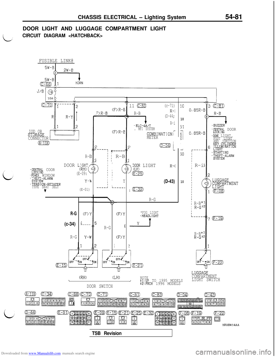
Downloaded from www.Manualslib.com manuals search engine CHASSIS ELECTRICAL - Lighting System54-81DOOR LIGHT AND LUGGAGE COMPARTMENT LIGHT
LCIRCUIT DIAGRAM
FUSIBLE LINK@I
I
IOD ORSTaRAGE
CONNECTOR
(A-11X)
R-E
DOOR LIGHT/.f;;$yik COOR
.POWER WINDOW';;gX$MALARM
.TENSION-RE3UCER
TYPE SEAT 3ELT
v
(RH)(E-09:
Y-b
(E-01)
R-G
(c-34)
R-G
(F)Y
4-----
(F>R-E=)R-B
(F>R-E
)
-----1 r-----/
,; ~ R-BII /
>
I/ II I1; cII II IIY/ ,----Ji-----
R-G
(F)Y
E
(F)Y
1
11 (c-83)(c-71)
R-B
i
(D-44;
.ELCdA/TR-i
. MFI SYSTEM
COMBINATIONrMETER
)
>
iX;? LIGHTR-c
m
(D-43)
l(E-32)
R-G
*FOG LIGHT.HEADLIGHT
-2-l
1C
10
51
$I1',1
SO
10
(RH)(LH)NOTE\/:l:UP TO 1995 MODELS
DOOR SWITCH%2:FROM 1996 MODELS
0.85R-1
0.85R-I
r----'/I/II
R-iI
I
/IIIII/(III/I
i R-B"I R-G":
/IL----.
R-B"R-G";
=I.BUZZER'L"RN;RP.k DOOR
.DOME LIGHT.FOOT LIGHT
AND IGNITION
KEY.CYLINDER6 &L#'NAT'ON
-STARTING.;yE;;iALARMj
7(F-19)
LUGGAGE
COMPARTMENT
LIGHT SWITCH
HR08M14AA
TSB Revision
Page 578 of 738
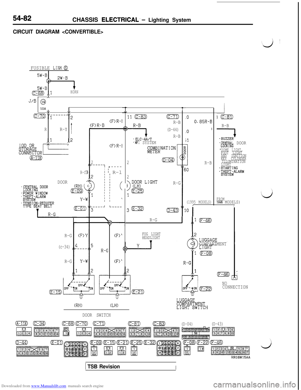
Downloaded from www.Manualslib.com manuals search engine 54-82CHASSIS ELECTRICAL. - Lighting System
CIRCUIT DIAGRAM
FUSIBLE LINKG
2W-B
5W-B(c-68) ,,lHORN/ m
J/B @
10A\I\,
(C-70)y-----3
I
(RR-Y
-1
(A-31X)
-2 I
R-f3
DOORC
R-B
QJ-fE#& DOOR
*DOME LIGHT,FOOT LIGHT
AND IGNITION
KEY CYLINDER
ILLUMINATION
LIGHT
-STARTINGjtjg&ALARM
t
11 (C-83)(c-71)
9
R-B
(D-44)
.ELC-4A/TR-B
.MFI SYSTEM
2
.O0.85R-B(F)R-I:F)R-B
(F)R-I
2
_----7 r----
I' I R-l2II
011 (
1 I/
I I\
.Ot
jl
3R-B
(1995 MODELS)
30
;0
2
R-G
FROM1996 MODELS),.----JI-----
R-G
' f
l(F-46)
R-G
(c-34)
R-G
FOG LIGHT
HEADLIGHT
vCOMPARTMENT
(F>‘
I---_
(F>‘
(F)'
NOCONNECTION
r=
(RH)(LH)
DOOR SWITCH
o(C-34)(c-68)Fml m(c-81)(c-83)
(D-04)(D-43)
HROBM15AA
1 TSB RevisionI