Engine control module MITSUBISHI 3000GT 1994 2.G Service Manual
[x] Cancel search | Manufacturer: MITSUBISHI, Model Year: 1994, Model line: 3000GT, Model: MITSUBISHI 3000GT 1994 2.GPages: 738, PDF Size: 35.06 MB
Page 187 of 738
Downloaded from www.Manualslib.com manuals search engine CIRCUIT DIAGRAMS - Cooling Circuit185
OPERATIONThe engine control module controls the power
transistors (high speed and low speed) in the moduleto provide radiator fan motor and condenser fan
motor rotation controls in accordance with the engine
coolant temperature and vehicle speed.
NOTEIn the event of faulty water temperature sensor,
the engine control module commands the fan motors
(for both radiator and condenser) to rotate at high
speeds.1. Radiator Fan (Low Speed Rotation)
l
When the engine control module turns onthe power transistor (low speed) in the
module, the current flows from the ignition
switch to the engine control module throughthe radiator fan motor relay (LO) coil.
If the current flows to the fan motor relay
coil, the switch of the relay turns on to supplythe motor driving power (for low speed
rotation). This will cause the current to flow
from the battery to the ground through the
radiator fan motor, relay switch and resistor,rotating the radiator fan at low speeds.
2. Condenser Fan (Low Speed Rotation)
l
The power from the NC compressor lock
controller turns on the condenser fan motorrelay (LO) to rotate the condenser fan at
low speeds.3. Radiator Fan, Condenser Fan (High
Speed Rotation)l
When the engine control module turns onthe power transistor (high speed) in the
module. the radiator fan motor relay (HI)
and condenser fan motor relay (HI) will
operate and the motor driving power (for
high speed rotation) is sent to the radiator
fan motor and condenser fan motor to rotate
the radiator fan and condenser fan at high
speeds.
TROUBLESHOOTING HINTS1. Neither the radiator fan nor condenser
fan rotate at all.
l Check fusible link No. 5.
2. Only the condenser fan does not
operate.l Check dedicated fuse No. 8.
3. The condenser fan do not operate in the
low speed mode, but operate otherwise.
(1) The A/C compressor magnet clutch does
not enter the “ON” state.l Check whether the output of the air
conditioning compressor lock controller
unit is available.
(2) The A/C compressor magnet clutch enters
the “ON” state.l
Check the condenser fan motor relay
(LO)-4. The radiator fan and condenser fan do
not operate in the high speed mode, but
operate otherwise.l Check the engine control unit.
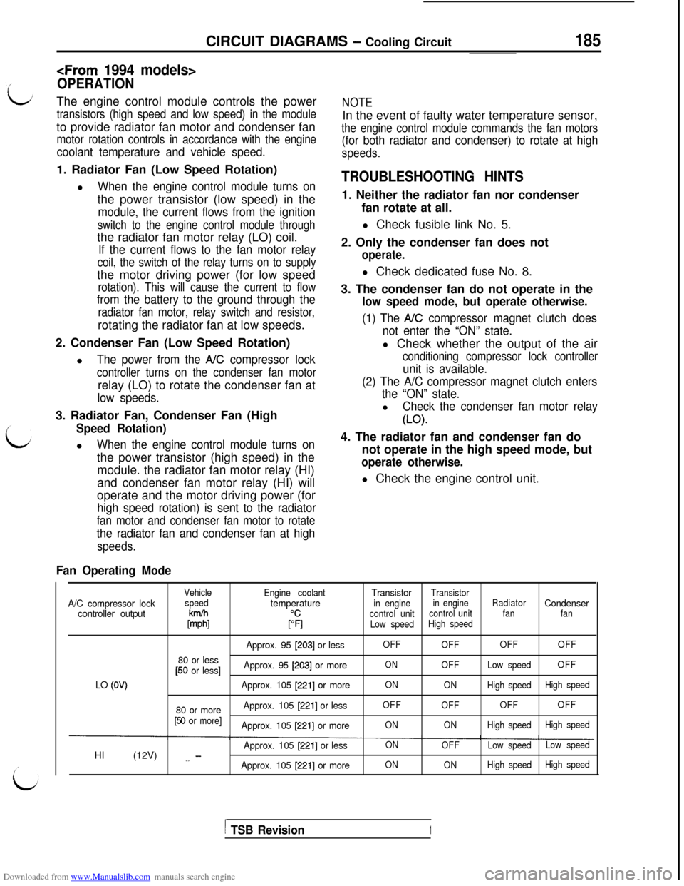
Fan Operating Mode
VehicleA/C compressor lockspeedcontroller output
k%
80 or less[50 or less]
LO
(OV)
80 or more[50 or more]HI (12V)
,_ -
Engine coolanttemperature
$1
Approx. 95 [203] or less
Approx. 95
[203] or more
Approx. 105
[221] or more
Approx. 105
[221] or less
Approx. 105
[221] or more
Approx. 105
[221] or less
Approx. 105
12211 or moreTransistor
Transistor
in enginein engineRadiatorCondensercontrol unitcontrol unitfanfan
Low speedHigh speed
OFF
OFFOFFOFF
ONOFFLow speedOFF
ON
ONHigh speedHigh speed
OFF
OFFOFFOFF
ONONHigh speedHigh speed
ON
OFFLow speedLow speed
ON
ONHigh speedHigh speed
1 TSB Revision1
Page 189 of 738
Downloaded from www.Manualslib.com manuals search engine CIRCUIT DIAGRAMS - ELC-4 A/T Circuit187 ,
IGNITSWITC
2L-B-___-__-___--_
10A
L-R
(c-30)
L-R
L-R
IN:IG2)
L-R
OVERDRI
VESWITCH(c-45)&G!K’
L-F%
MODULE
Z-DI+-l-LJ
TAILLIGHT RELAY
(R-G)3s' I
I!
d:m
G-Y
&y?~- ----- ------14
I
(B-Y)R-W A!:&RUISE
b!J#%JiSECONTROL* CONTROLI7
.
El
AUTO-
#@L R-WUNIT
R-y loI(c-37)
iHR07MOOAB
TSB Revision
Page 190 of 738
Downloaded from www.Manualslib.com manuals search engine 188CIRCUIT DIAGRAMS - EL(=-4 A/T Circuit
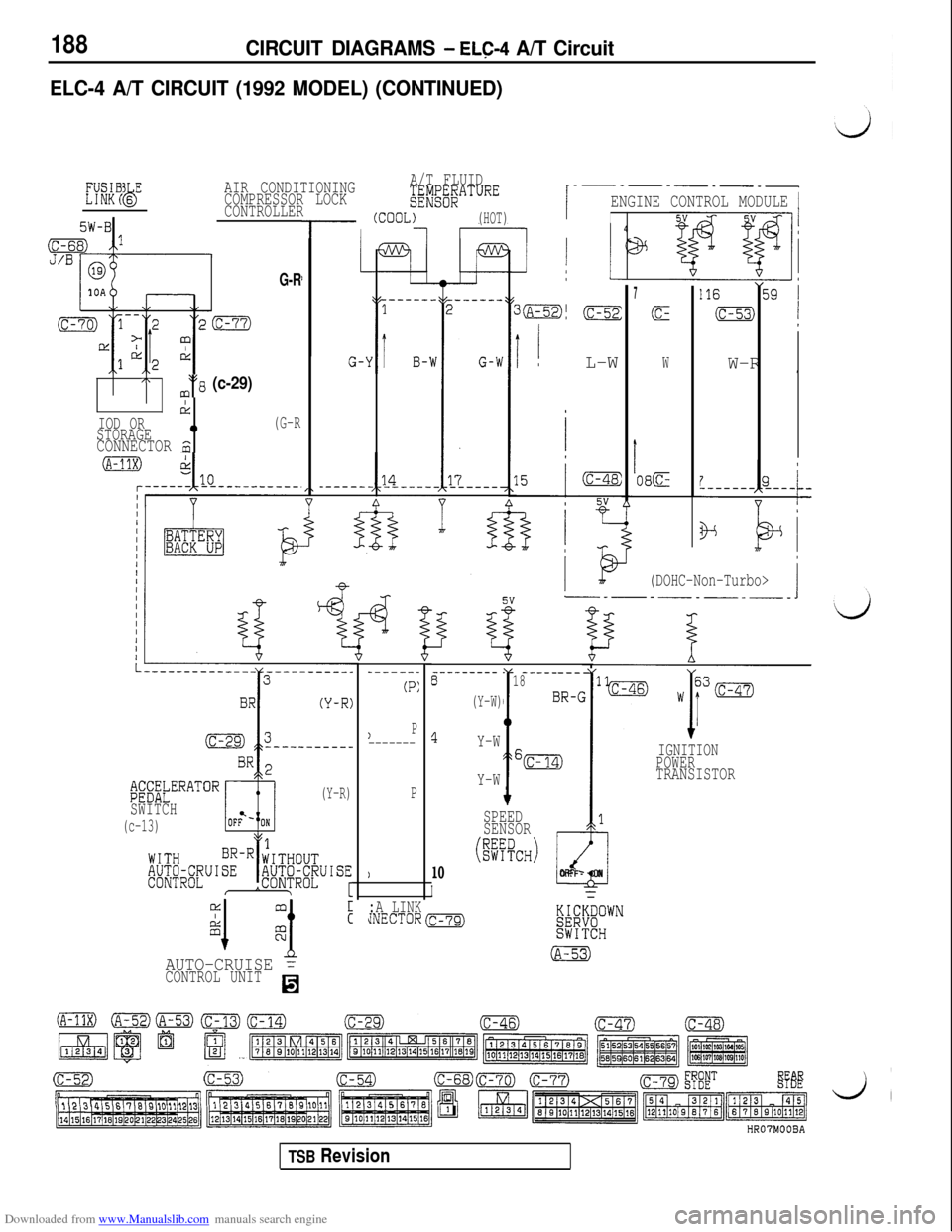
ELC-4 A/T CIRCUIT (1992 MODEL) (CONTINUED)
MGB6 EbAIR CONDITIONINGA/T FLUID
COMPRESSOR LOCK
CONTROLLER$$/g;;ATURE
I
--_-----_-
ENGINE CONTROL MODULE 1
I (cooL)(HOT)I45W-B1
G-RI1
G-‘
_-----
i
3o,(c-52:
7
(c-
I ! L-WWW-R II\3 (c-29)
drIOD OR0(G-RSTORAGECONNECTOR m^
I08E
(DOHC-Non-Turbo>
6--------- -_______818
(Y-W)
BR-C
4Y-W
Y-W
I
6m
10
I
SPEED
SENSOR
(@%*)
.I
1
‘iOFF- ON
------_
(P:
)P-------
P
)
IGNITION
POWER
TRANSISTOR;;;XbERATOR(Y-R)
SWITCH
(c-13)
AUTO-CRUISE =CONTROL UNITH
:A LINKJNECTOR-
HR07MOOBA
TSB Revision
Page 191 of 738
Downloaded from www.Manualslib.com manuals search engine CIRCUIT DIAGRAMS - ELC-4 AK Circuit
PULSEGENERATOR B &%iATDR A
1l-----J-
L
i?I
JL-----?----.
B
_---_
59_---_
(A-54)
i-_-
--_
G
.-- _3
'.- _-A
4
s
-_--
1--_
w
.--.
a--
E
LL-,
ENGINE CONTROL MODULEI
5V3
GND GND GNDGND
1 ’
GNDA
.---- -----_-$1
, j
72
1.25B
Y-R
1B/,4/-\ 1
-
IC
1
,V
v_ ‘JVI---
05 lm 62
BB
0
HROTMOOBB
TSB Revision
Page 194 of 738
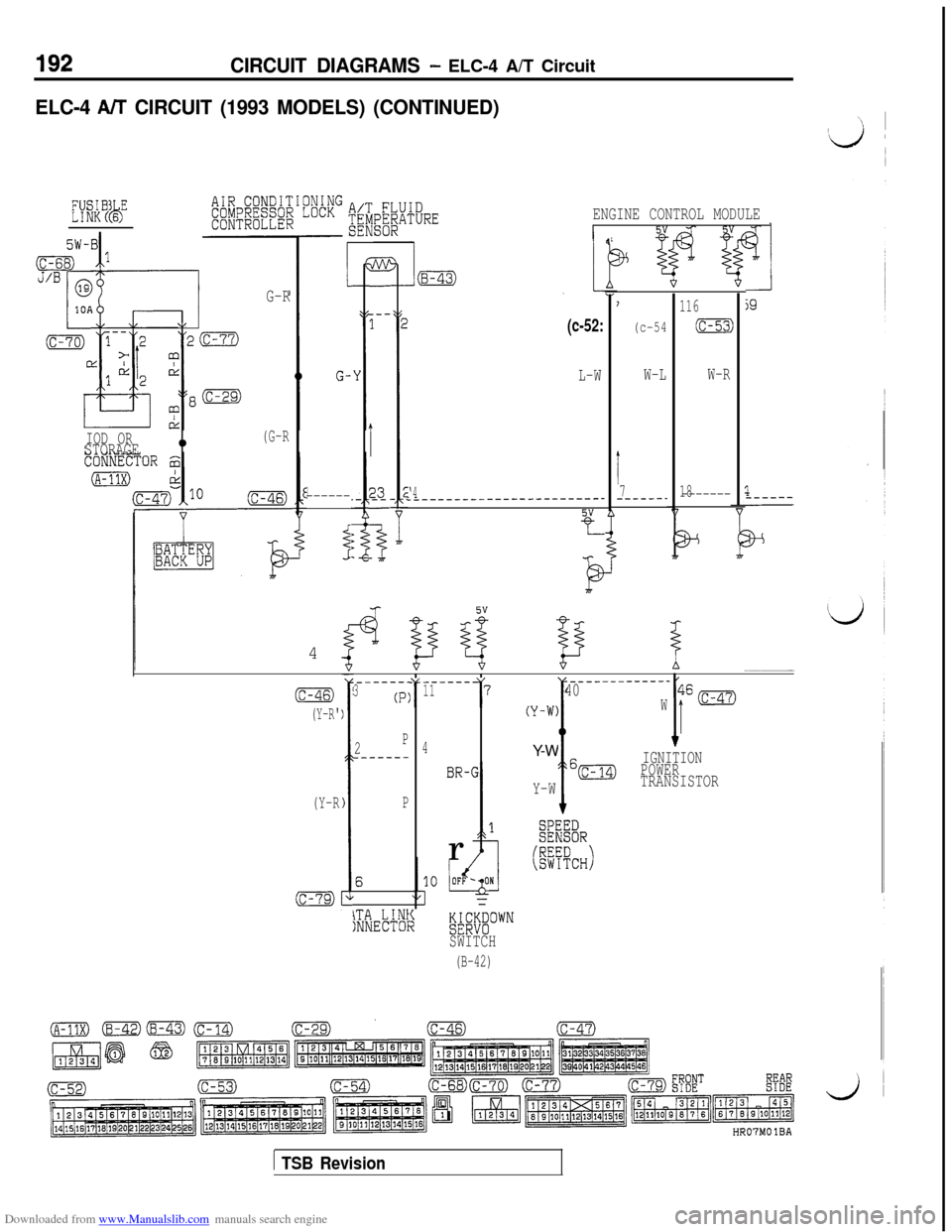
Downloaded from www.Manualslib.com manuals search engine 192CIRCUIT DIAGRAMS - ELC-4 A/T Circuit
ELC-4 W CIRCUIT (1993 MODELS) (CONTINUED)
EYWKB6 E(4ENGINE CONTROL MODULEI4
7
(c-54
W-L
I7------.
116
(c-53)
W-R
181,-------_-----
5W-Bi
m-
---1
I
23L
3
4
1
G-
3------
i254
G-R
\/
IOD OR0(G-RSTORAGE
(c-52:
L-W
‘4L_-----------------------
Y
-r
1
____-_-------40W(Y-W)Y-W
I
6m
Y-WIGNITION
POWERTRANSISTOR
;46
I’
(c-47)(c-46)
(Y-R'T
-_----11
4
BR-1r
17_-----_3(P:
2P__-----
P
\TA LINtINNECTOISWITCH
(B-42)
(Y-R
HR07MO IBA
1 TSB Revision
Page 195 of 738
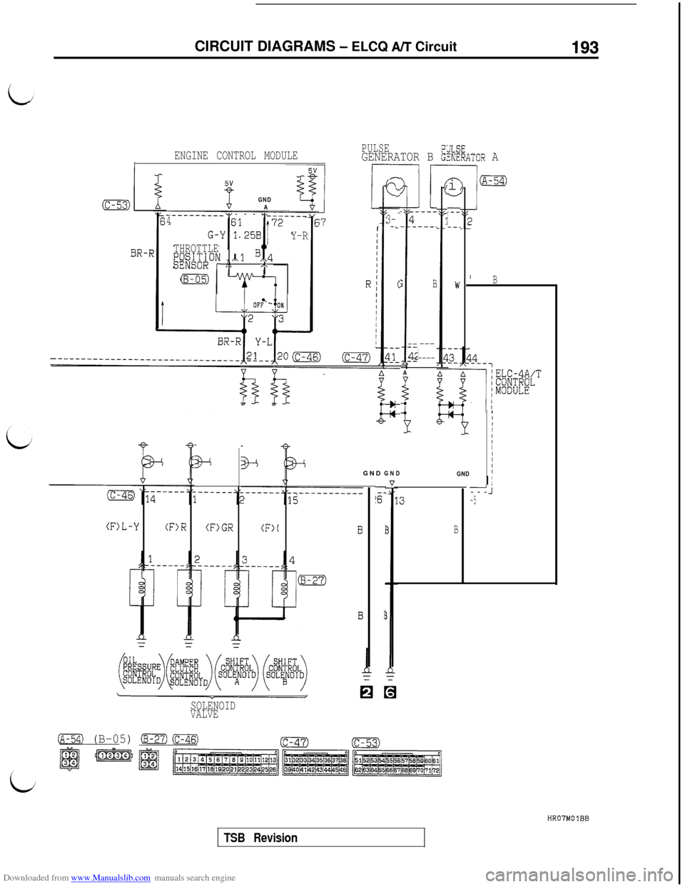
Downloaded from www.Manualslib.com manuals search engine CIRCUIT DIAGRAMS - ELCQ A/T Circuit193
ENGINE CONTROL MODULEPULSE
IGENERATOR B k%:ATOR A
l-----I
/xn
IciV
-.--I--.
IB
IIII/IIIIIGNDI
(c-53)4 AGND-____--___ ----- --__4---i73-- -.IY-R
BR-FTHROTTLEE;;&ON /xl B,,4A/\
(B-05)
. _4- -
;
L
--
4;---
A
!L
L_---
---.
B
---)----
i+GND GND
-
is-
I
E
I I_I’---J-5
(F>L-Y(F>R(F)GR(F>IB
SOLENOID
VALVE
(A-54) (B-05) (B-27)(=)
i-1
cc-47)(c-53)
HRO'IMOlBB
TSB Revision
Page 198 of 738
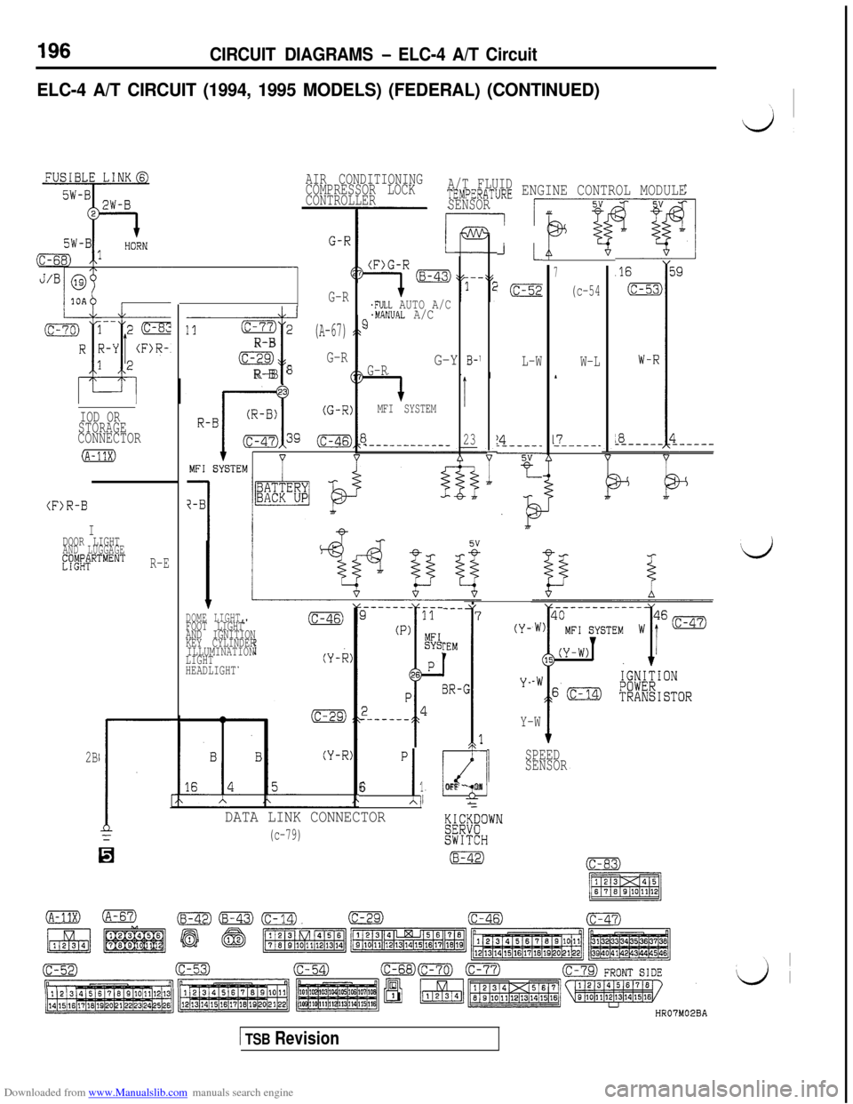
Downloaded from www.Manualslib.com manuals search engine CIRCUIT DIAGRAMS - ELC-4 A/T Circuit
ELC-4 A/T CIRCUIT (1994, 1995 MODELS) (FEDERAL) (CONTINUED)
d
A/T FLUIDTEMPERATURE ENGINE CONTROL MODULE
SENSOR AIR CONDITIONING
COMPRESSOR LOCK
CONTROLLER
JL
l(c-52
L-W
!4----..
-----w-
T--
.FULL AUTO A/C.MAN'JAL A/C3
G-Y B-1G-R
MFI SYSTEMT
23.---_-----___ __
7
(c-54
W-L
17------_ G-R
11(c-77)2
----s
R-B
(c-29)
R-B 8
(A-67)
G-R
IOD OR
STORAGE
CONNECTOR
(A-11X)
(F>R-B
IDOOR LIGHTAND LUGGAGE~~ld~~"'"""'R-E‘d
DOME LIGHT,FOOT LIGHT
AND IGNITION
KEY CYLINDER
ILLUMINATION
LIGHT
HEADLIGHT
P
-I
61
G
1OFF - ON
-
Y-W
1
SPEED
SENSOR
(Y-
Y-
2B
DATA LINK CONNECTOR
(c-79)HR07M02BA
1 TSB Revision
Page 199 of 738
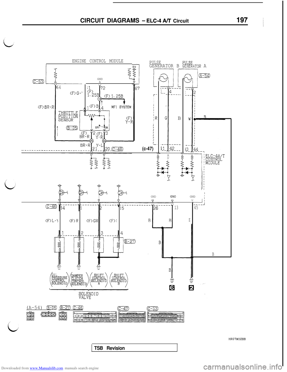
Downloaded from www.Manualslib.com manuals search engine CIRCUIT DIAGRAMS - ELC-4 A/T Circuit197 (
ENGINE CONTROL MODULEIPULSEGENERATOR B :k%ATOR A
l-----l/
I-.
r-I
I
I
IIIII
IRII1IIIII/L.
(c-47)
2Lll------_34-------_
G B
i
.-- -_--_
?A- _42_--
(F>BR-R64I
(F)G-‘GND
zA
A
V
1GND /GNDIGNDV
--4----45
B
(F)L-I(F)R(F)GR(F)(
13
E
(A-54) (B-05) iB-27)(-(c-47)(c-53)
4-pHR07M02BB
TSB Revision
Page 202 of 738
Downloaded from www.Manualslib.com manuals search engine 200CIRCUIT DIAGRAMS - ELC-4 A/T Circuit
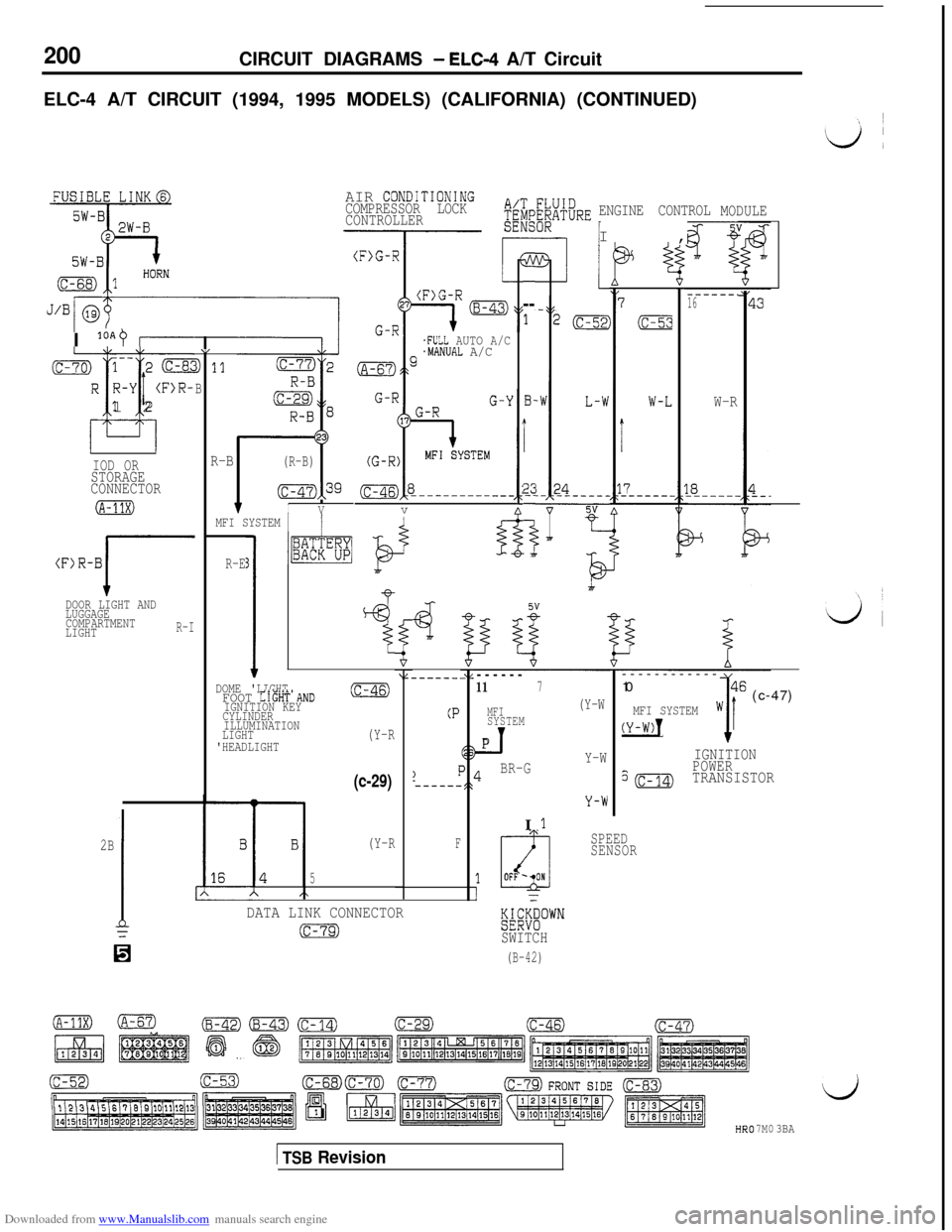
ELC-4 A/T CIRCUIT (1994, 1995 MODELS) (CALIFORNIA) (CONTINUED)
AIR CONDiTIONINGCOMPRESSOR LOCK
CONTROLLERENGINE CONTROLI,MODULE
3---
1
B-
i
2;-
i
7
SW-RI +
------.16
W-RI
loAO I.FULL AUTO A/C.MANUAL A/C
v(c-70) 1-- 2 (c-8cR R-Y
(F>R-
T-i
i12
1,
D 11
B
R-B(R-B)
(c-47),39
fIV
IOD ORSTORAGE
CONNECTOR
(A-11X)MFI SYSTEM 1/
(F)R-B
JDOOR LIGHT AND
LUGGAGE
COMPARTMENT
LIGHT
R-I
R-E3
1
I1~%“BF
4
l-
“i------
117
MFI(Y-W
SYSTEM
_TPI
BR-GY-W------------
10
w46 (c-47)MFI SYSTEM
(Y-W)!1I
IGNITION
?(c-14)
POWERTRANSISTOR
DOME 'LIGHTFOOT LIGHT'AND(c-46)
IGNITION KEY
CYLINDER
ILLUMINATION
LIGHT
(Y-R'HEADLIGHT
(P
(c-29)
2B
1=
SPEED
SENSOR(Y-RF
5
DATA LINK CONNECTOR
(c-79)%%““”SWITCH
(B-42)H
7M03BA
1 TSB Revision
Page 203 of 738
Downloaded from www.Manualslib.com manuals search engine CIRCUIT DIAGRAMS - ELC-4 A/T Circuit201
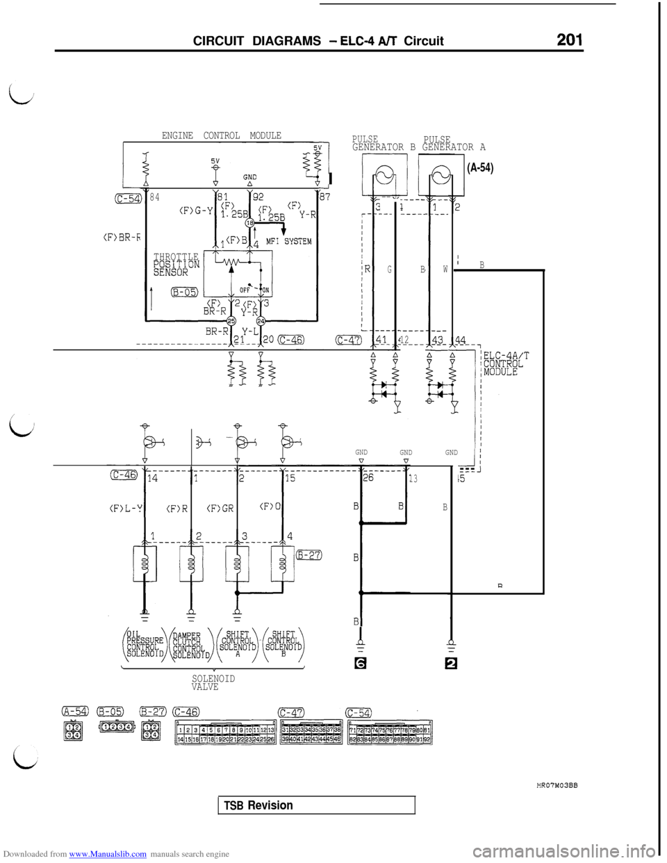
1
PULSEPULSEGENERATOR B GENERATOR A
ENGINE CONTROL MODULE
(F>BR-I;
(A-54)
4. iGNDI I
-----1----.
B
.----
12.--_-
I
--
---
W
r_3_-
z-
,
IIB
?-4-,
GNDI I
-I
17L
r/I/III/I
IFII,IIIII
&-
84
(F>G
--,_--
G
THROTTLE&E~'o~ON
a+GND
GNDQ0
wie -
-4---15
(F)R(F)GR
13
B(F>L-'
la
~~:~~~~~1~~~~~~-~~~~~~~~ i
LIa*SOLENOID
VALVE
HR07M03BB
TSB Revision