Compressor MITSUBISHI 3000GT 1994 2.G Workshop Manual
[x] Cancel search | Manufacturer: MITSUBISHI, Model Year: 1994, Model line: 3000GT, Model: MITSUBISHI 3000GT 1994 2.GPages: 738, PDF Size: 35.06 MB
Page 16 of 738
Downloaded from www.Manualslib.com manuals search engine 14GENERAL - Control Unit Location
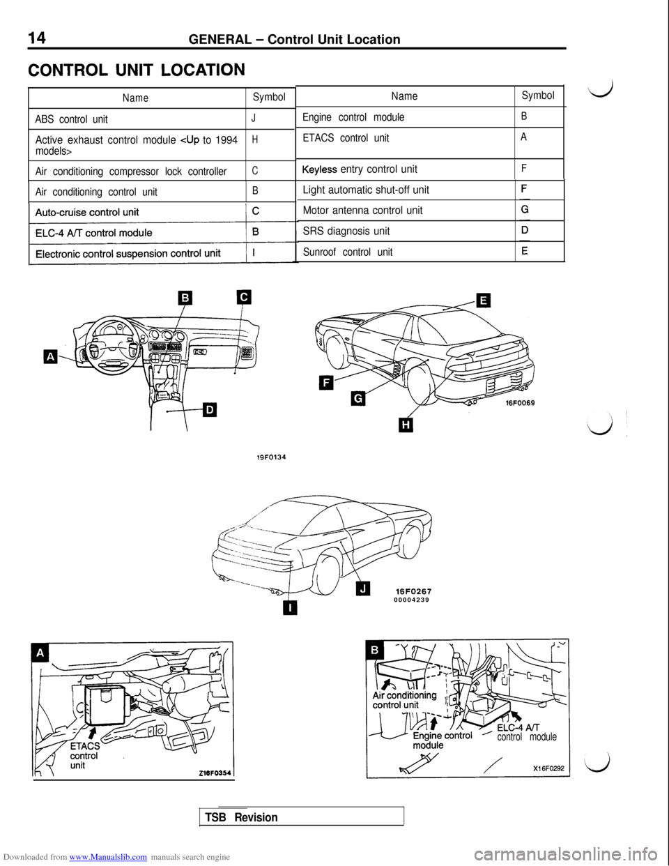
CONTROL UNIT LOCATION
NameSymbol
ABS control unit
J
Active exhaust control module cup to 1994H
models>
Air conditioning compressor lock controller
C
Air conditioning control unitB
Name
Engine control module
ETACS control unit
Keyless entry control unit
Light automatic shut-off unit
Motor antenna control unit
SRS diagnosis unit
Sunroof control unitSymbol
d
B
A
F
19FO134
16FO26700004239
control module
TSB Revision
Page 53 of 738
Downloaded from www.Manualslib.com manuals search engine CONFIGURATION DIAGRAMS - Dash Panel51
C-32c-33
A36F0179
00004255
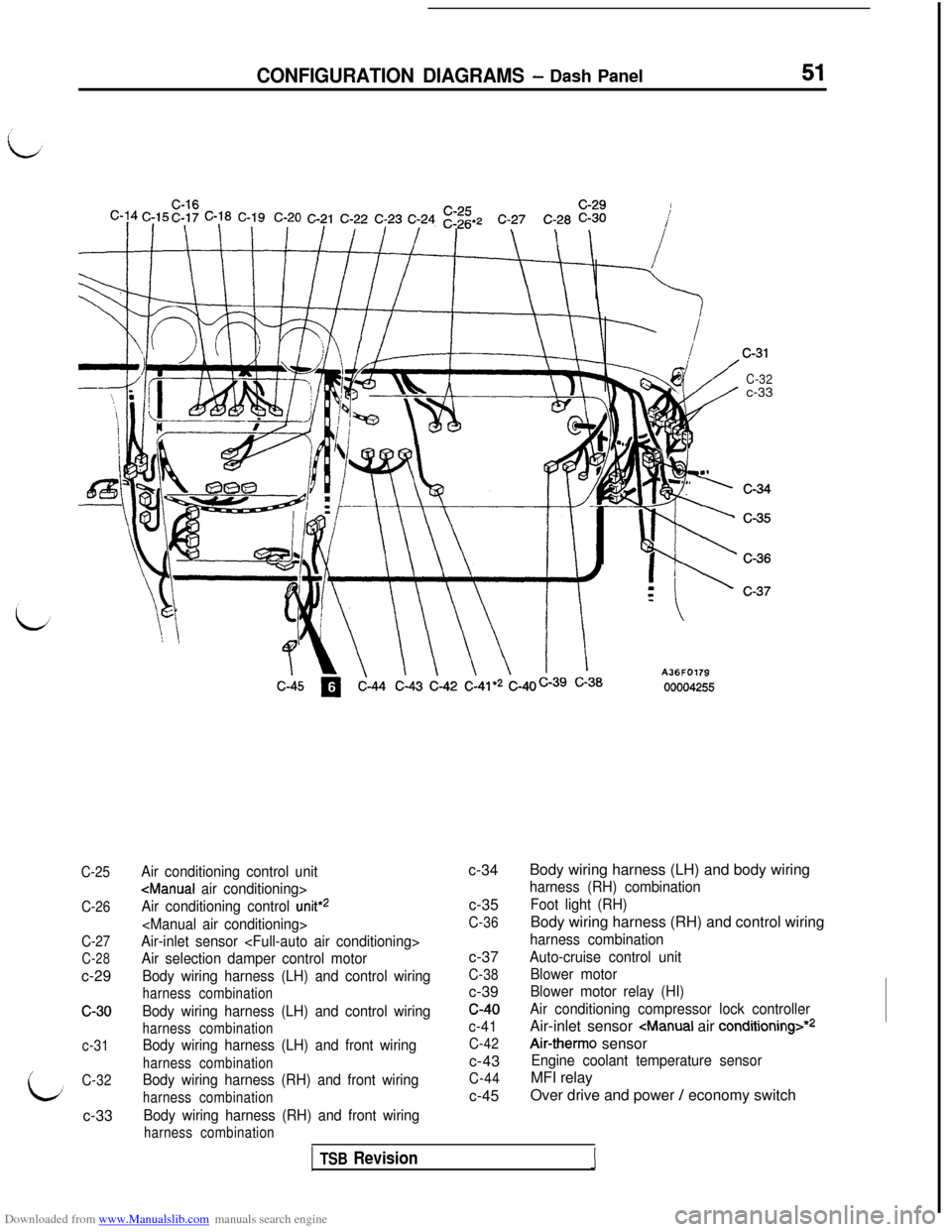
C-25
C-26
C-27
C-28c-29
c-30
c-31
C-32c-33
Air conditioning control unit
Air conditioning control
unit*2
Air-inlet sensor
Air selection damper control motor
Body wiring harness (LH) and control wiring
harness combination
Body wiring harness (LH) and control wiring
harness combination
Body wiring harness (LH) and front wiring
harness combination
Body wiring harness (RH) and front wiring
harness combination
Body wiring harness (RH) and front wiring
harness combinationc-34
c-35
C-36c-37
C-38c-39c-40
c-41
C-42c-43
C-44c-45Body wiring harness (LH) and body wiring
harness (RH) combination
Foot light (RH)Body wiring harness (RH) and control wiring
harness combination
Auto-cruise control unit
Blower motor
Blower motor relay (HI)
Air conditioning compressor lock controllerAir-inlet sensor
Air-therm0 sensor
Engine coolant temperature sensorMFI relay
Over drive and power
/ economy switch
TSB Revision1
Page 73 of 738
Downloaded from www.Manualslib.com manuals search engine CIRCUIT DIAGRAMS - Power Distribution Circuit71
I
/
2B-Y>:5IOD OR
%iMOR
1
B-W
I2B-W
.ENGINECONTROL MODULE.IGNITION COIL.IGNITION POWERTRANSISTOR,MFI RELAY
'REMOTECONTROLLED
MIRROR
.&~[E"~ORY
.ETACS UNITL
TRANSAXLE
f%m"
I
*tf@'$ESS CONTROL
.REAR
INTERMITTENT
WIPER RELAY.AUTO-CRUISECONTROL UNIT.WASHER MOTOR.ETACS UNIT.WIPER MOTOR.MOTOR ANTENNA.WIPER RELAYCONTROL UNIT$~~CJ&~AND TAPE:ABS
POWER RELAY.CONDENSOR 7
(UP TO 1993 October)AiFAyOTOR
.BACK UP LIGHT.LIGHT AUTOMATICSHUT-OFF UNIT
G~GAERoCONTROL UNIT.SPARECONNECTOR+J;&~L"U'SE
MAIN SWITCH(#&i;iE).AIR CONDITIONINGCOMPRESSOR LOCK
CONTROLLER$&JTR.INIC
SUSPENSION.AIR CONDITIONINGCONTROL UNITCONTROL UNIT*RADIATOR*&L"$R MOTORFAN MOTOR
RELAY
.#&lyCRUISE
$i$&NATION$$;NATION
.ETACS UNIT.MOTOR ANTENNACONTROL UNIT
.SPEED SENSbR.ggTDIAGNOSI~
.TURN SIGNALAND HAZARD
FLASHER UNIT.BLOWER MOTORRELAYCHI)
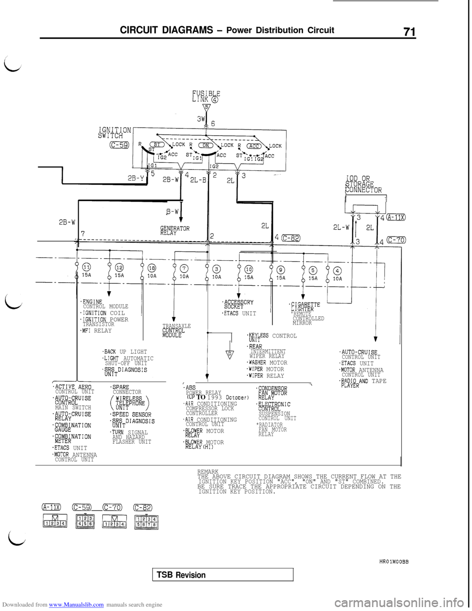
REMARKTHE ABOVE CIRCUIT DIAGRAM SHOWS THE CURRENT FLOW AT THEIGNITION KEY POSITION "ACC", "ON" AND "ST" COMBINED.BE SURE TRACE THE APPROPRIATE CIRCUIT DEPENDING ON THEIGNITION KEY POSITION.
0 (c-59) (c-70) (c-82)
~giJJ~jq$q
LHROlMOOBB
TSB Revision
Page 77 of 738
Downloaded from www.Manualslib.com manuals search engine CIRCUIT DIAGRAMS - Power Distribution Circuit75
IGNITION3y; 6
SWITCH
(c-59)
I
IGlVI
2B-YpL52B-W *2L-BIOD OR%ii&!OR
II
B-W
JGENERATOR7RELAY__-_--_-_____-___-_____________
2B-W
.ENGINECONTROL MODULE.IGNITION COIL.IGNITION POWERTRANSISTOR.MFI RELAYTRANSAXLE
ki8%EL
f
,BACK UP LIGHT.LIGHT AUTOMATICSHUT-OFF UNIT$$~TDIAGNOSIS
I$
'ABSPOWER RELAY(UP TO 1993 October).AIR CONDITIONINGCOMPRESSOR LOCK
CONTROLLER
.AIR CONDITIONINGCONTROL UNIT'&#R MOTOR
.BLOWER MOTORRELAYCHI)
.--_--
.&EE;qORY
.ETACS UNIT
+ L-l'#fiBi;'"
.REMOTECONTROLLED
MIRROR
+jjf$ESS CONTROLic
.REARINTERMITTENT
WIPER RELAY
.WASHER MOTOR.WIPER MOTOR.WIPER RELAY
.AUTO-CRUISECONTROL UNIT.ETACS UNIT.MOTOR ANTENNACONTROL UNIT.RADIO ANDTAPE PLAYER.ACTIVE AERO\
CONTROL UNIT.SPARECONNECTOR$@RC~UISE
MAIN SWITCH(jiifb%E)
~f$J&CRUISE.SPEED SENSOR
~'$@~NATION$/$TDIAGNOSIS
.&y&NATION.TURN SIGNALAND HAZARD
FLASHER UNIT
.ETACS UNIT.MOTOR ANTENNACONTROL UNIT
T
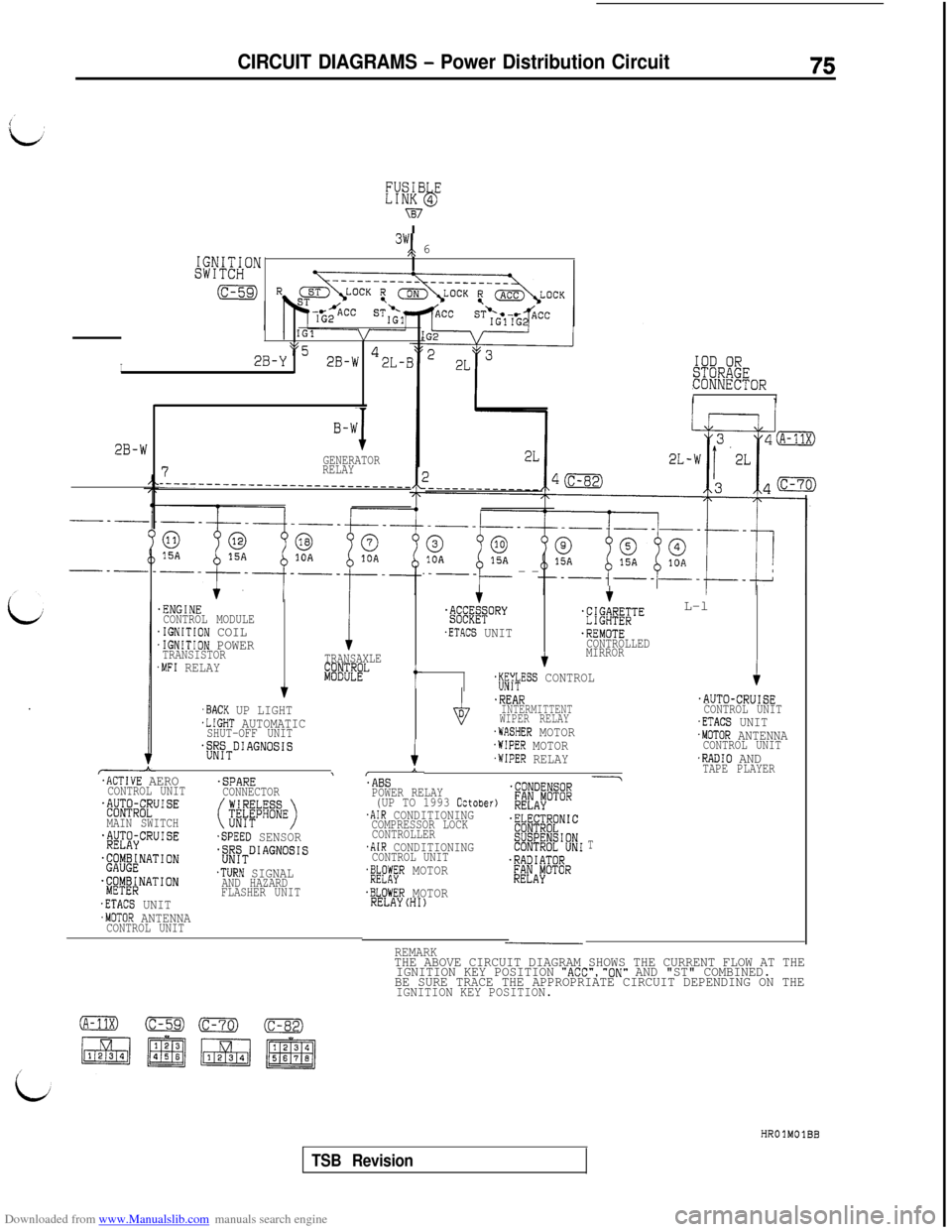
REMARKTHE ABOVE CIRCUIT DIAGRAM SHOWS THE CURRENT FLOW AT THE
IGNITION KEY POSITION "ACC","ON" AND "ST" COMBINED.
BE SURE TRACE THE APPROPRIATE CIRCUIT DEPENDING ON THE
IGNITION KEY POSITION.
HROlMOlBB
TSB Revision
Page 85 of 738
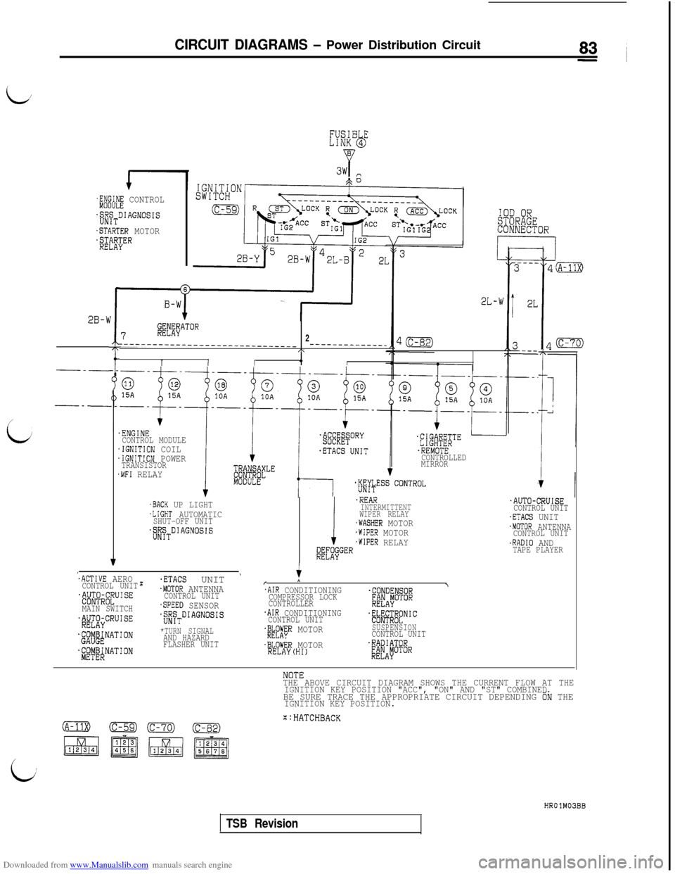
Downloaded from www.Manualslib.com manuals search engine CIRCUIT DIAGRAMS - Power Distribution Circuit
L,
FUSIB ELINK 4bB
P3w P
$$d! CONTROL
jj!JyTDIAGNOSIS
.STARTER MOTOR$$eEl?ER
2L-w
:
J
I
2B-b
7@#"TO"
2__-__--__-__-_--_--_--~~-~~-~-- -_-----__-_--_C\
1I/4,/---t-_
/
i/.ENGINECONTROL MODULE.IGNITION COIL.IGNITION POWERTRANSISTOR.MFI RELAY
.REMOTECONTROLLED
MIRROR
.AUTO-CRUISECONTROL UNIT.ETACS UNIT.MOTOR ANTENNACONTROL UNIT.RADIO ANDTAPE PLAYER
.BACK UP LIGHT.LIGHT AUTOMATICSHUT-OFF UNIT.;;~TDIAGNOSIS
i
.REARINTERMITTENT
WIPER RELAY
.WASHER MOTOR.WIPER MOTOR.WIPER RELAY@L"'$jGER
:ACTIVE AEROCONTROL UNIT~~~&~~U'SE
MAIN SWITCH$&CRUISE
.@j&NATION
$'~$!$NATION
:.ETACS UNIT '.MOTOR ANTENNACONTROL UNIT.SPEED SENSORjiyTDIAGNOSIS
*TURN SIGNALAND HAZARD
FLASHER UNITr
*
.AIR CONDITIONING\
COMPRESSOR LOCK.CONDENSOR
CONTROLLER;@AiOTOR
.AIR CONDITIONINGCONTROL UNIT.~@;~~NIC
.&A";R MOTORSUSPENSIONCONTROL UNIT
.BLOWER MOTOR.RADIATORRELAY(HI)&JAFOTOR
THE ABOVE CIRCUIT DIAGRAM SHOWS THE CURRENT FLOW AT THE
IGNITION KEY POSITION "ACC", "ON" AND "ST" COMBINED
BE SURE TRACE THE APPROPRIATE CIRCUIT DEPENDING ON THEIGNITION KEY POSITION.
X:HATCHBACK
HROlM03BB
TSB Revision
Page 177 of 738
Downloaded from www.Manualslib.com manuals search engine CIRCUIT DIAGRAMS - Cooling Circuit175
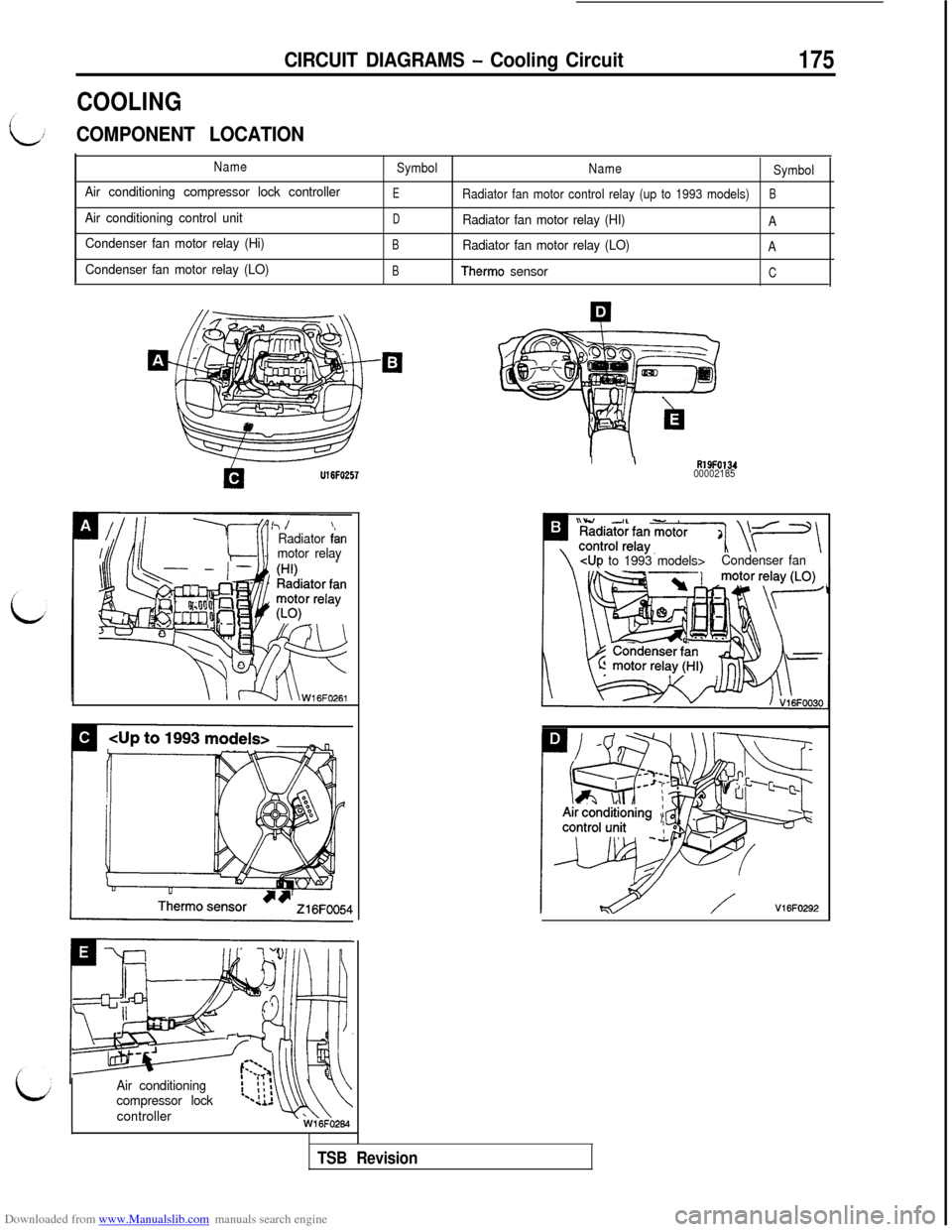
COOLING
COMPONENT LOCATION
Name
Air conditioning compressor lock controller
Air conditioning control unit
Condenser fan motor relay (Hi)
Condenser fan motor relay (LO)
Symbol
Name
Symbol
ERadiator fan motor control relay (up to 1993 models)B
D
Radiator fan motor relay (HI)A
BRadiator fan motor relay (LO)A
BTherm0 sensorC
U16FO257
3 IIRadiator fanmotor relay
Air conditioning
compressor lock
controller
I\R19F013400002185
:p ?GKli$~E[ \y\
\CUP to 1993 models>Condenser fan
V16FO292
TSB Revision
Page 181 of 738
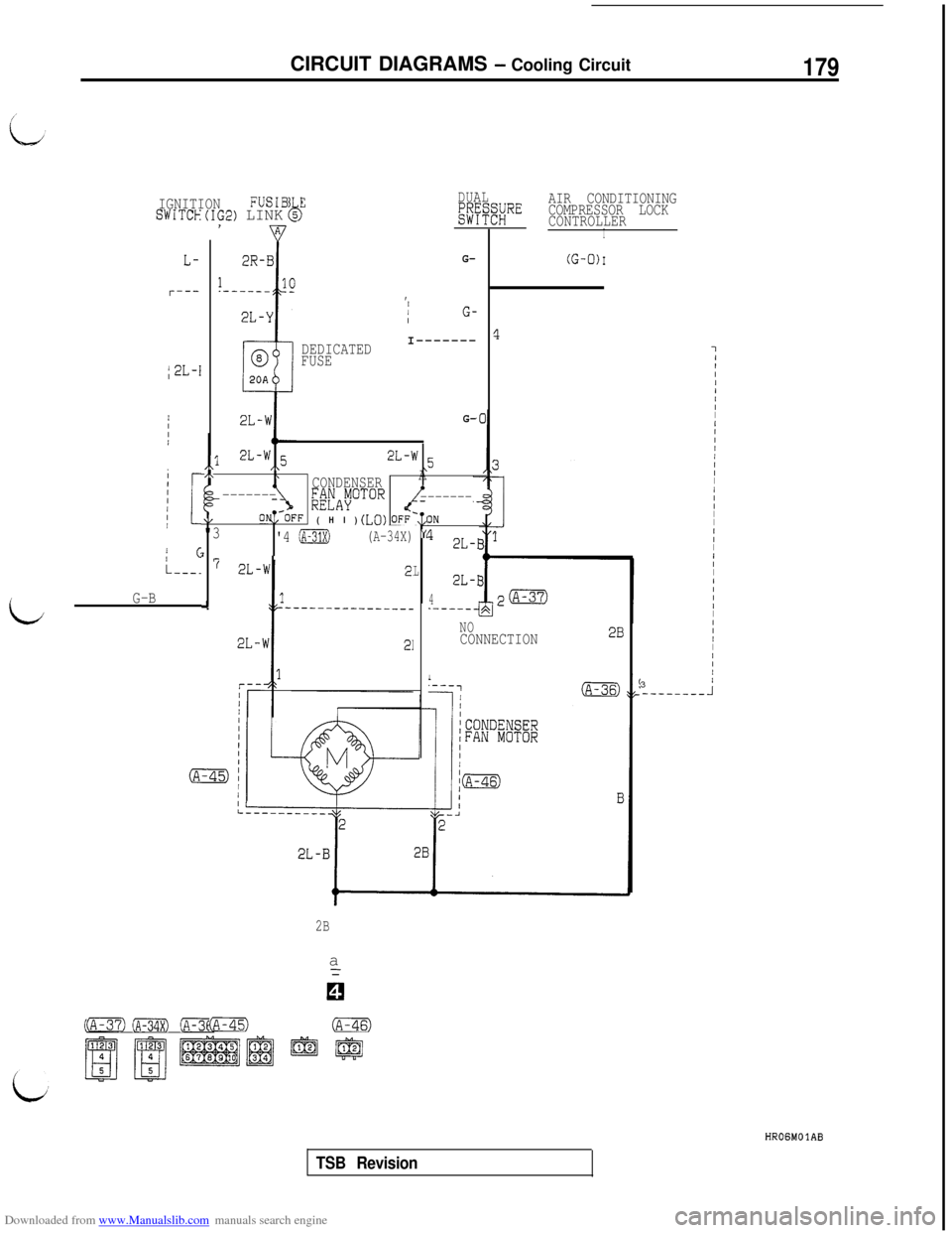
Downloaded from www.Manualslib.com manuals search engine CIRCUIT DIAGRAMS - Cooling Circuit179
IGNITIONFUSIB ESWITCH(IG2) LINK 5k
L-
r---
/2L-I
IIc
L---.
L
G-BDEDICATED
FUSE
DUAL~$~PX~~REAIR CONDITIONING
COMPRESSOR LOCK
CONTROLLER
I
G-
,/1G-II-------
G-
,,l2L-w 5/\2L-w 5\,\\CONDENSERA
-------;;FAvOTOR-------
\/@OFF(HI) (LO) OFF-,?"3'4 (A-31X)(A-34X) “L
I'iL
A
IN
1 2L-I
2L-I
4.---__4
(G-0)I
I7
NOCONNECTION28
I‘---7(A-36)
2Ba
(A-33X) (A-34X) (A-36)@im (A-45) (A-46)
IIIIIIII/IIIIIII/III
I
III/IIIIII
I
IIIIIII3/-----____I
HROGMOlAB
TSB Revision
Page 183 of 738
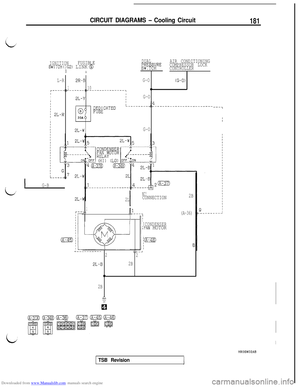
Downloaded from www.Manualslib.com manuals search engine CIRCUIT DIAGRAMS - Cooling Circuit181
idJ
IGNITIONFUSIB Eb
DUALAIR CONDITIONING
SWITCH(IG2) LINK 5l';~'~;RECOMPRESSOR LOCK
CONTROLLER
BA
L-R2R-BG-O(G-0)
1100r----+*------52---------------1I/I2L-Y/G-OII/II1L--------&----------------------I
/ 2L-RI
63%ELCATED
20AIIIII2L-wG-O
1G-B
1,:&--,(A-36)111II
1
Iw[CONDENSER,FAN MOTOR
M
I
NC!
2LCONNECTION2B
c----------t/,-i22
2L-B2B
0
2BI'
---7HROGM02AB
TSB Revision
Page 185 of 738
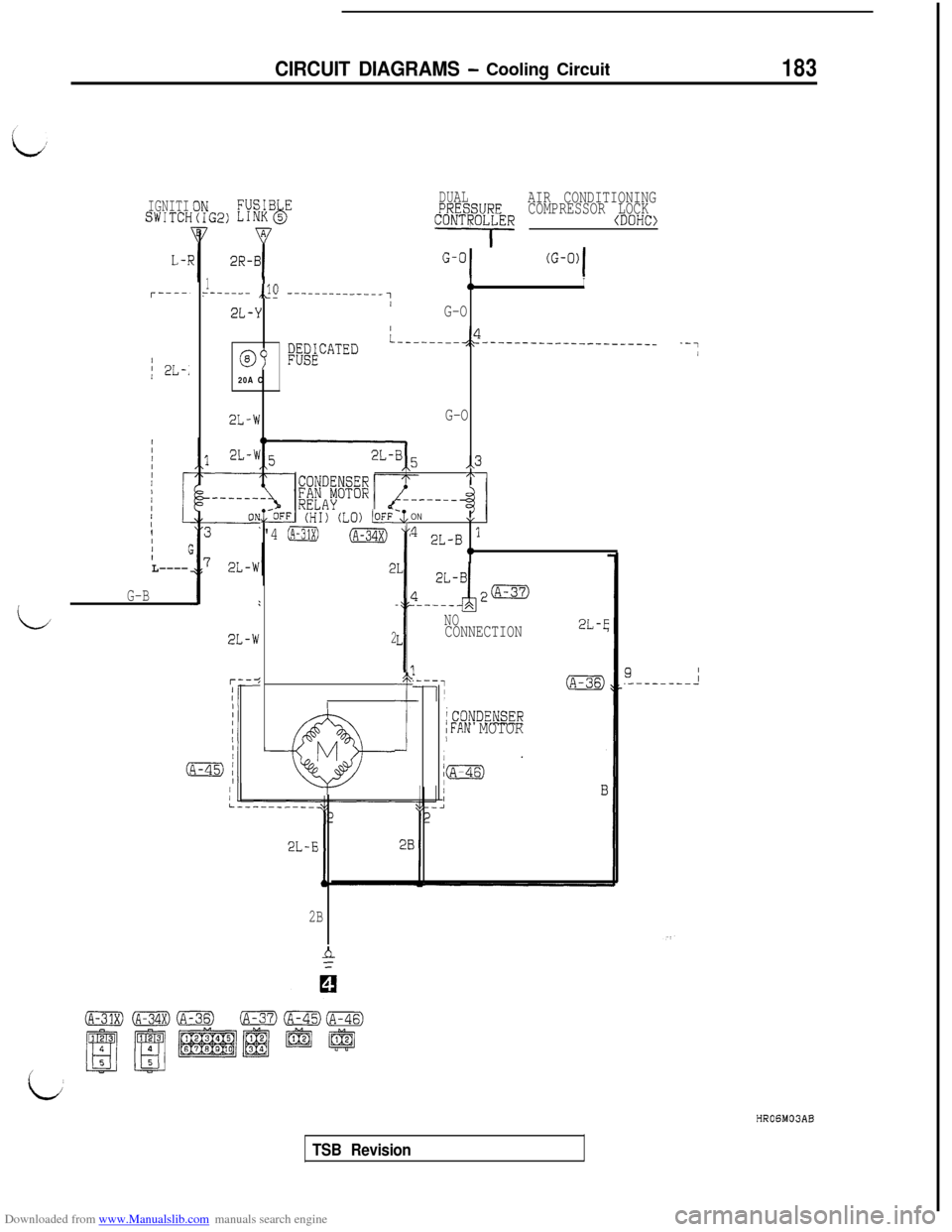
Downloaded from www.Manualslib.com manuals search engine CIRCUIT DIAGRAMS - Cooling Circuit183
IGNITISWITCf-
I; 2L-;
III(IL----
G-B
L
DUALg$FF%;;REAIR CONDITIONING
COMPRESSOR LOCK
CONTROL,LER (DOHC>,
IIIIII/I
@&
L
e
M
y----.- ,,lO --__--__-----_10I3/2L-Y1 /G-O
09WATED
L--------,2--______-___--_-______20A C
2L-WG-O
,,3h
7,,-OFF (HI) (LO) ti
"4 (A-31X)
ON1,
' 2L-B 10
2
I-
?
iCONDENSERIFAN MOTOR/
NOCONNECTION2L-E
2B
9II.--------_
i
HROGM03AB
TSB Revision
Page 186 of 738
Downloaded from www.Manualslib.com manuals search engine 184CIRCUIT DIAGRAMS - Cooling Circuit
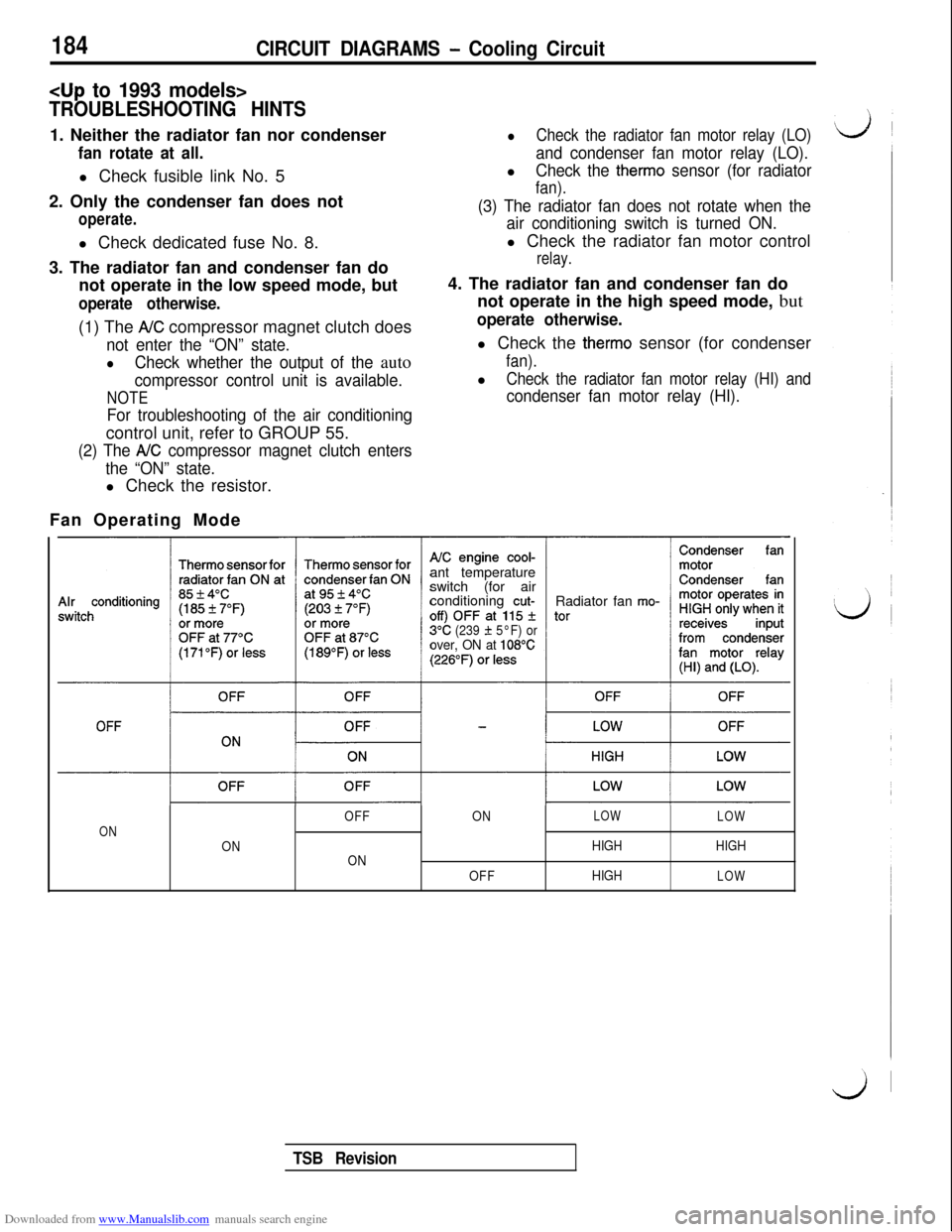
TROUBLESHOOTING HINTS1. Neither the radiator fan nor condenser
fan rotate at all.l Check fusible link No. 5
2. Only the condenser fan does not
operate.l Check dedicated fuse No. 8.
3. The radiator fan and condenser fan do
not operate in the low speed mode, but
operate otherwise.(1) The
AK compressor magnet clutch does
not enter the “ON” state.
lCheck whether the output of the auto
compressor control unit is available.
NOTE
For troubleshooting of the air conditioningcontrol unit, refer to GROUP 55.
(2) The A/C compressor magnet clutch enters
the “ON” state.l Check the resistor.
lCheck the radiator fan motor relay (LO)
and condenser fan motor relay (LO).l
Check the therm0 sensor (for radiator
fan).
(3) The radiator fan does not rotate when the
air conditioning switch is turned ON.l Check the radiator fan motor control
relay.4. The radiator fan and condenser fan do
not operate in the high speed mode, but
operate otherwise.l Check the
therm0 sensor (for condenser
fan).l
Check the radiator fan motor relay (HI) and
condenser fan motor relay (HI).Fan Operating Mode
ant temperature
switch (for air
conditioning
cut-Radiator fan mo-
3°C(239 f 5°F) orover, ON at 108°C
OFFONLOW
LOW
ON
ONHIGHHIGH
ON
OFFHIGH
LOW
TSB Revision