Disc MITSUBISHI 3000GT 1994 2.G Workshop Manual
[x] Cancel search | Manufacturer: MITSUBISHI, Model Year: 1994, Model line: 3000GT, Model: MITSUBISHI 3000GT 1994 2.GPages: 738, PDF Size: 35.06 MB
Page 26 of 738
Downloaded from www.Manualslib.com manuals search engine 24GENERAL - Harness Connector Inspection
ess connector
contact pressure
checking harness
201 R057
Z16R1317
HARNESS CONNECTOR INSPECTION
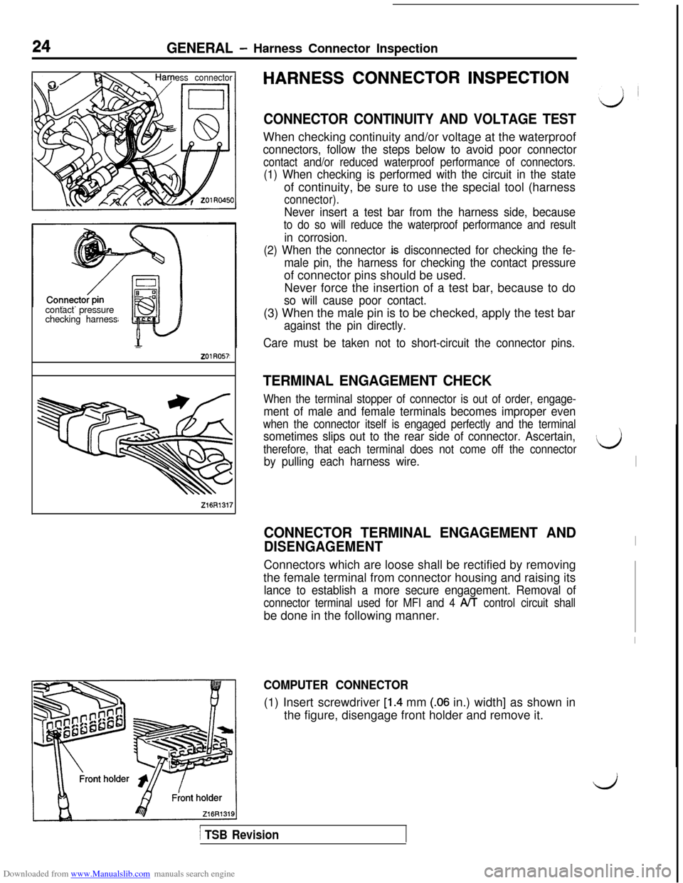
CONNECTOR CONTINUITY AND VOLTAGE TESTWhen checking continuity and/or voltage at the waterproof
connectors, follow the steps below to avoid poor connector
contact and/or reduced waterproof performance of connectors.
(1) When checking is performed with the circuit in the stateof continuity, be sure to use the special tool (harness
connector).
Never insert a test bar from the harness side, because
to do so will reduce the waterproof performance and result
in corrosion.
(2) When the connector
JS disconnected for checking the fe-
male pin, the harness for checking the contact pressureof connector pins should be used.
Never force the insertion of a test bar, because to do
so will cause poor contact.(3) When the male pin is to be checked, apply the test bar
against the pin directly.
Care must be taken not to short-circuit the connector pins.
TERMINAL ENGAGEMENT CHECK
When the terminal stopper of connector is out of order, engage-
ment of male and female terminals becomes improper even
when the connector itself is engaged perfectly and the terminal
sometimes slips out to the rear side of connector. Ascertain,
therefore, that each terminal does not come off the connector
by pulling each harness wire.
CONNECTOR TERMINAL ENGAGEMENT AND
DISENGAGEMENTConnectors which are loose shall be rectified by removing
the female terminal from connector housing and raising its
lance to establish a more secure engagement. Removal of
connector terminal used for MFI and 4 A/l control circuit shallbe done in the following manner.
COMPUTER CONNECTOR(1) Insert screwdriver
[1.4 mm (.06 in.) width] as shown in
the figure, disengage front holder and remove it.
1 TSB Revision
IJ
I
I
I
Page 34 of 738
Downloaded from www.Manualslib.com manuals search engine 32GENERAL - How to Diaanose
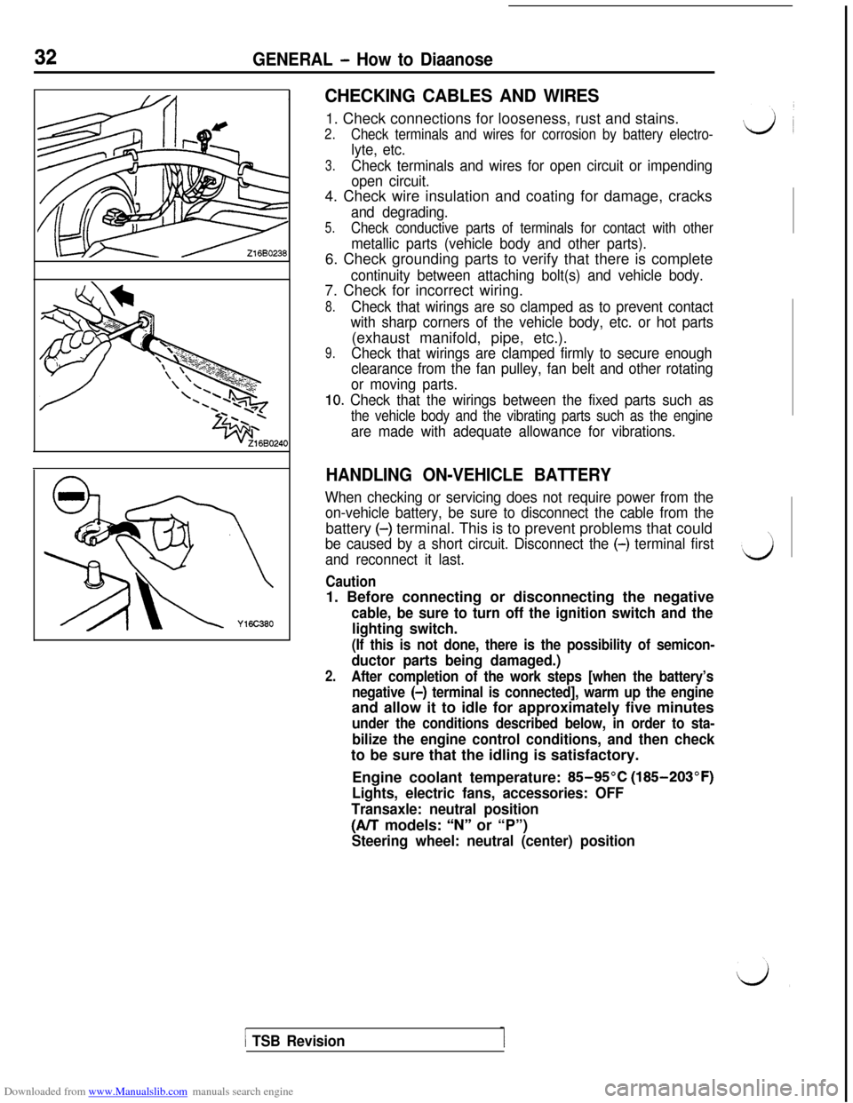
CHECKING CABLES AND WIRES1. Check connections for looseness, rust and stains.
2.Check terminals and wires for corrosion by battery electro-
lyte, etc.
3.Check terminals and wires for open circuit or impending
open circuit.4. Check wire insulation and coating for damage, cracks
and degrading.
5.Check conductive parts of terminals for contact with other
metallic parts (vehicle body and other parts).6. Check grounding parts to verify that there is complete
continuity between attaching bolt(s) and vehicle body.7. Check for incorrect wiring.
8.Check that wirings are so clamped as to prevent contact
with sharp corners of the vehicle body, etc. or hot parts(exhaust manifold, pipe, etc.).
9.Check that wirings are clamped firmly to secure enough
clearance from the fan pulley, fan belt and other rotating
or moving parts.
10. Check that the wirings between the fixed parts such as
the vehicle body and the vibrating parts such as the engine
are made with adequate allowance for vibrations.
HANDLING ON-VEHICLE BATTERY
When checking or servicing does not require power from the
on-vehicle battery, be sure to disconnect the cable from thebattery
(-) terminal. This is to prevent problems that could
be caused by a short circuit. Disconnect the (-) terminal first
and reconnect it last.
Caution1. Before connecting or disconnecting the negative
cable, be sure to turn off the ignition switch and the
lighting switch.
(If this is not done, there is the possibility of semicon-
ductor parts being damaged.)
2.After completion of the work steps [when the battery’s
negative (-)
terminal is connected], warm up the engineand allow it to idle for approximately five minutes
under the conditions described below, in order to sta-
bilize the engine control conditions, and then checkto be sure that the idling is satisfactory.
Engine coolant temperature:
85-95°C (185-203°F)
Lights, electric fans, accessories: OFF
Transaxle: neutral position
(A/T models: “N” or “P”)
Steering wheel: neutral (center) position
1 TSB Revision
Page 36 of 738
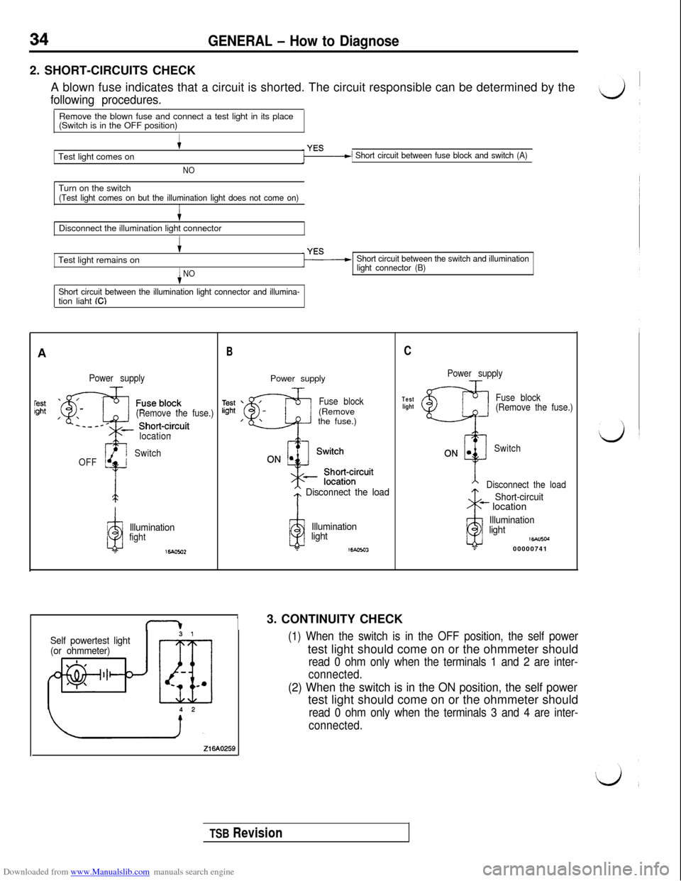
Downloaded from www.Manualslib.com manuals search engine GENERAL - How to Diagnose2. SHORT-CIRCUITS CHECK
A blown fuse indicates that a circuit is shorted. The circuit responsible can be determined by the
following procedures.Remove the blown fuse and connect a test light in its place
(Switch is in the OFF position)
Test light comes on
+
NO
1 Short circuit between fuse block and switch (A)Turn on the switch
(Test light comes on but the illumination light does not come on)ItDisconnect the illumination light connector
I+Test light remains on
iNO
Short circuit between the illumination light connector and illumina-tion liaht ((3
Short circuit between the switch and illumination
light connector (B)A
Power supply
(Remove the fuse.)
1OFF
gi
location
Switch
a
Illuminationfight
16.4om2
BPower supply
Fuse block(Remove
the fuse.)
* Disconnect the load
iii
Illumination
light
T16Aom
13. CONTINUITY CHECK
Self powertest light
(or ohmmeter)
Z16AO269
C
Power supply
Test
lightFuse block
(Remove the fuse.)
Switch
Disconnect the load
ii
Short-circuit- location
Illumination
light
16Alncd?00000741
(1) When the switch is in the OFF position, the self powertest light should come on or the ohmmeter should
read 0 ohm only when the terminals 1 and 2 are inter-
connected.
(2) When the switch is in the ON position, the self powertest light should come on or the ohmmeter should
read 0 ohm only when the terminals 3 and 4 are inter-
connected.
TSB Revision
Page 451 of 738
Downloaded from www.Manualslib.com manuals search engine ENGINE ELECTRICAL - Charging System16-5
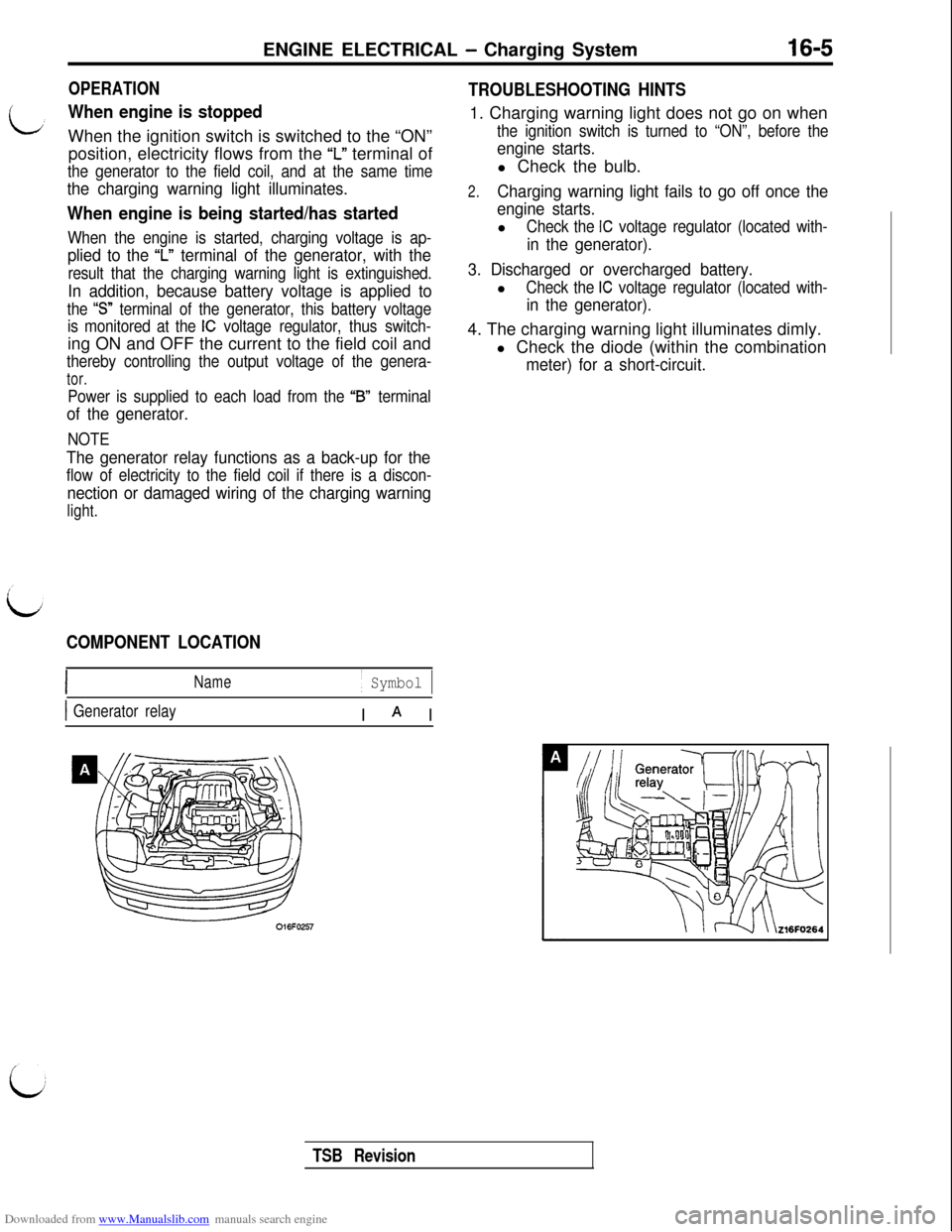
OPERATION
When engine is stoppedWhen the ignition switch is switched to the “ON”
position, electricity flows from the
‘I” terminal of
the generator to the field coil, and at the same time
the charging warning light illuminates.
When engine is being started/has started
When the engine is started, charging voltage is ap-
plied to the ‘I” terminal of the generator, with the
result that the charging warning light is extinguished.
In addition, because battery voltage is applied to
the “S” terminal of the generator, this battery voltage
is monitored at the
IC voltage regulator, thus switch-ing ON and OFF the current to the field coil and
thereby controlling the output voltage of the genera-
tor.
Power is supplied to each load from the “B” terminal
of the generator.
NOTE
The generator relay functions as a back-up for the
flow of electricity to the field coil if there is a discon-
nection or damaged wiring of the charging warning
light.
COMPONENT LOCATION
Name/ Symbol 1
1 Generator relayI A I
TROUBLESHOOTING HINTS1. Charging warning light does not go on when
the ignition switch is turned to “ON”, before the
engine starts.l Check the bulb.
2.Charging warning light fails to go off once the
engine starts.l
Check the IC voltage regulator (located with-
in the generator).
3. Discharged or overcharged battery.l
Check the IC voltage regulator (located with-
in the generator).4. The charging warning light illuminates dimly.
l Check the diode (within the combination
meter) for a short-circuit.
TSB Revision
Page 452 of 738
Downloaded from www.Manualslib.com manuals search engine 16-6ENGINE ELECTRICAL - Charging System
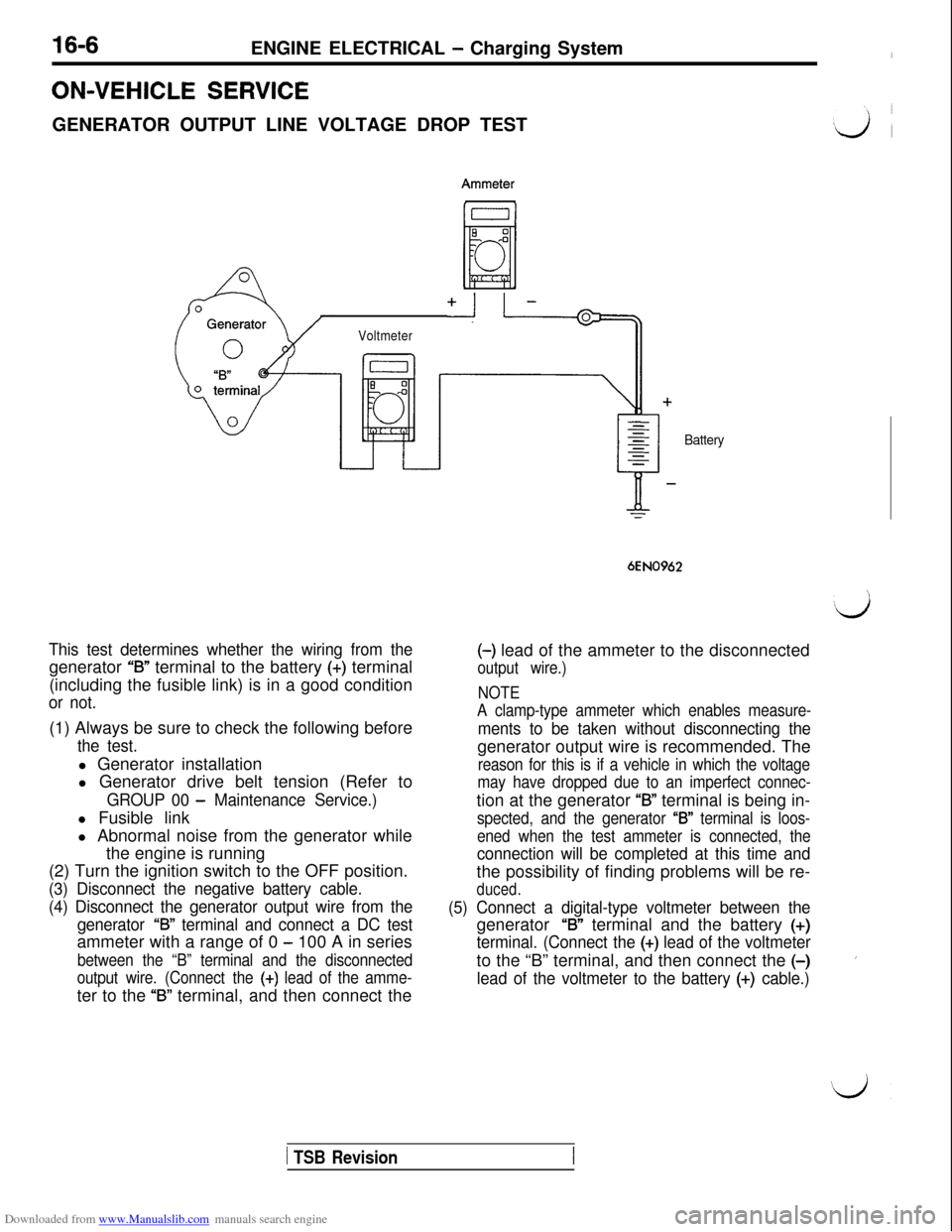
ON-VEHICLE SERVICEGENERATOR OUTPUT LINE VOLTAGE DROP TEST
+I I.=-@=
Voltmeter
This test determines whether the wiring from thegenerator
“B” terminal to the battery (+) terminal
(including the fusible link) is in a good condition
or not.(1) Always be sure to check the following before
the test.l Generator installation
l Generator drive belt tension (Refer to
GROUP 00 - Maintenance Service.)l Fusible link
l Abnormal noise from the generator while
the engine is running
(2) Turn the ignition switch to the OFF position.
(3) Disconnect the negative battery cable.
(4) Disconnect the generator output wire from the
generator
‘73” terminal and connect a DC testammeter with a range of 0
- 100 A in series
between the “B” terminal and the disconnected
output wire. (Connect the
(+) lead of the amme-ter to the
‘73” terminal, and then connect the
Battery
6EN0962(-) lead of the ammeter to the disconnected
output wire.)
NOTE
A clamp-type ammeter which enables measure-
ments to be taken without disconnecting thegenerator output wire is recommended. The
reason for this is if a vehicle in which the voltage
may have dropped due to an imperfect connec-tion at the generator
“B” terminal is being in-
spected, and the generator “B” terminal is loos-
ened when the test ammeter is connected, the
connection will be completed at this time andthe possibility of finding problems will be re-
duced.
(5) Connect a digital-type voltmeter between thegenerator
“B” terminal and the battery (+)
terminal. (Connect the (+) lead of the voltmeterto the “B” terminal, and then connect the
(-)
lead of the voltmeter to the battery (+) cable.)
’
1 TSB Revision
Page 453 of 738
Downloaded from www.Manualslib.com manuals search engine ENGINE ELECTRICAL - Charging System16-7/
L
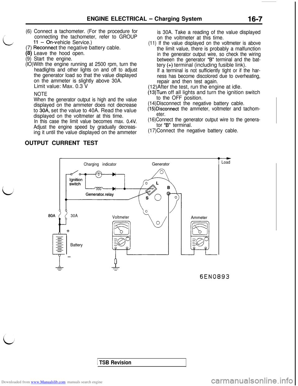
(6) Connect a tachometer. (For the procedure for
connecting the tachometer, refer to GROUP
- On-vehicle Service.)(7)
kkconnect the negative battery cable.
(8) Leave the hood open.
(9) Start the engine.
(lO)With the engine running at 2500 rpm, turn the
headlights and other lights on and off to adjust
the generator load so that the value displayed
on the ammeter is slightly above 30A.Limit value: Max. 0.3 V
NOTE
When the generator output is high and the value
displayed on the ammeter does not decreaseto
30A, set the value to 40A. Read the value
displayed on the voltmeter at this time.
In this case the limit value becomes max. 0.4V.
Adjust the engine speed by gradually decreas-
ing it until the value displayed on the ammeterOUTPUT CURRENT TEST
is 30A. Take a reading of the value displayed
on the voltmeter at this time.
(11) If the value displayed on the voltmeter is above
the limit value, there is probably a malfunction
in the generator output wire, so check the wiring
between the generator
“IS” terminal and the bat-tery
(+) terminal (including fusible link).
If a terminal is not sufficiently tight or if the har-
ness has become discolored due to overheating,
repair and then test again.(12)After the test, run the engine at idle.
(13)Turn off all lights and turn the ignition switch
to the OFF position.
(14)Disconnect the negative battery cable.
(15)Disconnect the ammeter, voltmeter and tachom-
eter.
(16)Connect the generator output wire to the genera-
tor “B” terminal.
(17)Connect the negative battery cable.
Charging indicatorGenerator
30A
Voltmeter
BatteryAmmeter
t
-Load
6EN0893
1 TSB Revision
Page 454 of 738
Downloaded from www.Manualslib.com manuals search engine 16-8ENGINE ELECTRICAL - Charging System
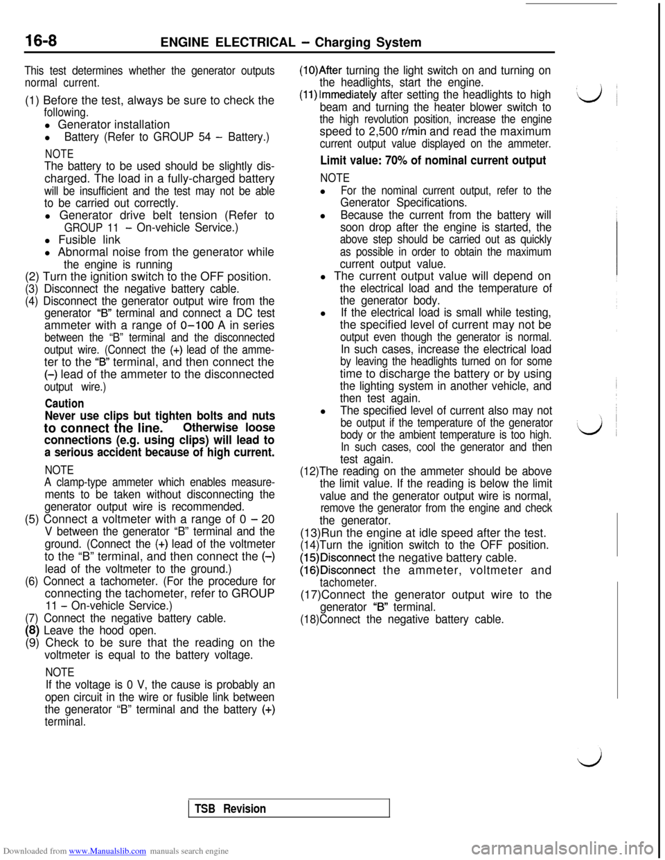
This test determines whether the generator outputs
normal current.(1) Before the test, always be sure to check the
following.l Generator installation
l
Battery (Refer to GROUP 54 - Battery.)
NOTE
The battery to be used should be slightly dis-charged. The load in a fully-charged battery
will be insufficient and the test may not be able
to be carried out correctly.l Generator drive belt tension (Refer to
GROUP 11- On-vehicle Service.)l Fusible link
l Abnormal noise from the generator while
the engine is running(2) Turn the ignition switch to the OFF position.
(3) Disconnect the negative battery cable.
(4) Disconnect the generator output wire from the
generator
“B” terminal and connect a DC testammeter with a range of O-100 A in series
between the “B” terminal and the disconnected
output wire. (Connect the
(+) lead of the amme-ter to the
“B” terminal, and then connect the(-) lead of the ammeter to the disconnected
output wire.)
Caution
Never use clips but tighten bolts and nutsto connect the line.
Otherwise loose
connections (e.g. using clips) will lead to
a serious accident because of high current.
NOTE
A clamp-type ammeter which enables measure-
ments to be taken without disconnecting the
generator output wire is recommended.(5) Connect a voltmeter with a range of 0
- 20
V between the generator “B” terminal and the
ground. (Connect the
(+) lead of the voltmeterto the “B” terminal, and then connect the (-)
lead of the voltmeter to the ground.)
(6) Connect a tachometer. (For the procedure forconnecting the tachometer, refer to GROUP
11 - On-vehicle Service.)
(7) Connect the negative battery cable.
(8) Leave the hood open.(9) Check to be sure that the reading on the
voltmeter is equal to the battery voltage.
NOTE
If the voltage is 0 V, the cause is probably an
open circuit in the wire or fusible link between
the generator “B” terminal and the battery
(+)
terminal.
(1O)After turning the light switch on and turning on
the headlights, start the engine.
(1l)lmmediately after setting the headlights to high
beam and turning the heater blower switch to
the high revolution position, increase the enginespeed to 2,500
r/min and read the maximum
current output value displayed on the ammeter.
Limit value: 70% of nominal current output
NOTEl
For the nominal current output, refer to the
Generator Specifications.l
Because the current from the battery will
soon drop after the engine is started, the
above step should be carried out as quickly
as possible in order to obtain the maximum
current output value.l The current output value will depend on
the electrical load and the temperature of
the generator body.l
If the electrical load is small while testing,the specified level of current may not be
output even though the generator is normal.
In such cases, increase the electrical load
by leaving the headlights turned on for sometime to discharge the battery or by using
the lighting system in another vehicle, and
then test again.l
The specified level of current also may not
be output if the temperature of the generator
body or the ambient temperature is too high.
In such cases, cool the generator and then
test again.
(12)The reading on the ammeter should be above
the limit value. If the reading is below the limit
value and the generator output wire is normal,
remove the generator from the engine and check
the generator.(13)Run the engine at idle speed after the test.
(14)Turn the ignition switch to the OFF position.
(15)Disconnect the negative battery cable.
(16)Disconnect the ammeter, voltmeter and
tachometer.(17)Connect the generator output wire to the
generator “B” terminal.
(18)Connect the negative battery cable.
TSB Revision
Page 455 of 738
Downloaded from www.Manualslib.com manuals search engine ENGINE ELECTRICAL - Charging Svstem16-9REGULATED VOLTAGE TEST
\:
b
Ignitionswitch (IGl)Generator
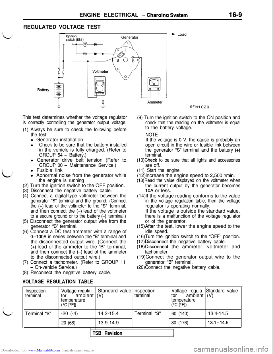
This test determines whether the voltage regulator
is correctly controlling the generator output voltage.
(1) Always be sure to check the following before
the test.l Generator installation
lCheck to be sure that the battery installedin the vehicle is fully charged. (Refer to
GROUP 54 - Battery.)l Generator drive belt tension (Refer to
GROUP 00 - Maintenance Service.)l Fusible link
l Abnormal noise from the generator while
the engine is running(2) Turn the ignition switch to the OFF position.
(3) Disconnect the negative battery cable.
(4) Connect a digital-type voltmeter between the
generator “S” terminal and the ground. (Connect
the
(+) lead of the voltmeter to the “s” terminal,
and then connect the (-) lead of the voltmeter
to a secure ground or to the battery (-) terminal.)
(5) Disconnect the generator output wire from the
generator
“B” terminal.(6) Connect a DC test ammeter with a range of
O-100A in series between the “B” terminal andthe disconnected output wire. (Connect the
(+) lead of the ammeter to the “B” terminal,
and then connect the (-) lead of the ammeter
to the disconnected output wire.)
(7) Connect a tachometer. (Refer to GROUP 11
- On-vehicle Service.)
(8) Reconnect the negative battery cable.
VOLTAGE REGULATION TABLE
Ammeter
- Load
6EN1029
(9) Turn the ignition switch to the ON position and
check that the reading on the voltmeter is equal
to the battery voltage.
NOTE
If the voltage is 0 V, the cause is probably an
open circuit in the wire or fusible link between
the generator
“S” terminal and the battery (+)
terminal.
(1O)Check to be sure that all lights and accessories
are off.
(11) Start the engine.(12)lncrease the engine speed to 2,500
r/min.
(13)Read the value displayed on the voltmeter when
the current output by the generator becomes
10A or less.
(14)lf the voltage reading conforms to the value
in the voltage regulation table, then the voltage
regulator is operating normally.If the voltage is outside the standard value,
there is a malfunction of the voltage regulator
or of the generator.
(15)After the test, lower the engine speed to the
idle speed.
(16)Turn the ignition switch to the “OFF” position.
(17)Disconnect the negative battery cable.
(18)Disconnect the ammeter, voltmeter and
tachometer.(19)Connect the generator output wire to the
generator “B” terminal.
(20)Connect the negative battery cable.
Inspection
terminal
Terminal “S”
Voltage regula-Standard value Inspection
torambient (V)terminal
temperature
(“C PI)-20 (-4)14.2-15.4
Terminal “S”
20 (68)13.9-14.9
TSB Revision
Voltage regula- Standard value
torambient (V)
temperature(“c
PI)
60 (140)13.4-14.5
80 (176)13.1-14.5
I
Page 469 of 738
Downloaded from www.Manualslib.com manuals search engine ENGINE ELECTRICAL - Starting System16-23
OPERATION
L
0For models equipped with the M/T, the clutch
pedal position switch contact is switched OFF
when the clutch pedal is depressed; when the
ignition switch is then switched to the “ST’ posi-tion, electricity flows to the starter relay and
the starter motor, the contact (magnetic switch)of the starter is switched ON and the starter
motor is activated.
NOTEIf the ignition switch is switched to the “ST
position without the clutch pedal being de-
pressed, electricity flows to the starter relay
(coil), the clutch pedal position switch (contacts)
and to ground, with the result that the contacts
of the starter relay are switched OFF, and, be-
cause the power to the starter motor is thereby
interrupted, the starter motor is not activated.lFor models equipped with the
AIT, when the
ignition switch is switched to the “ST’ position
while the selector lever is at the “P” or “N” posi-
tion, the contact (magnetic switch) of the starter
is switched ON and the starter motor is activated.
TROUBLESHOOTING HINTSThe starter motor does not operate at all.
l Check the starter (coil).
lCheck for poor contact at the battery terminals
and starter.l Check Park/Neutral position switch.
l Check clutch pedal position switch.
l Check starter relay.
l Check theft-alarm starter relay.
l Check key reminder switch.
i
/’
L&J
Fieldcoil wire
Iii?Stopper
IPinion gap
PinionZ6EL003
STARTER MOTORREMOVAL AND INSTALLATION
Refer to GROUP 22
- Manual Transaxle, or GROUP 23 -
Automatic Transaxle.INSPECTION
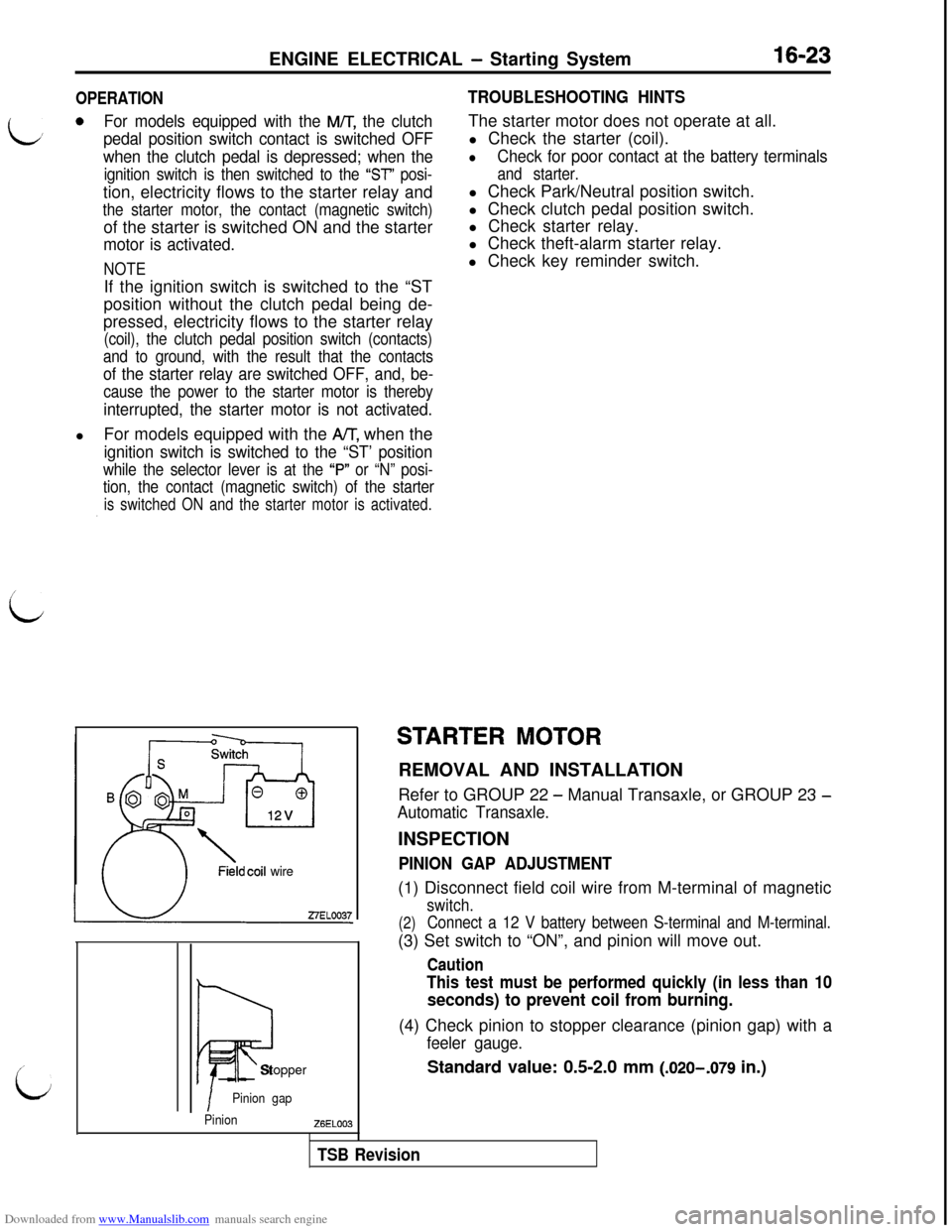
PINION GAP ADJUSTMENT(1) Disconnect field coil wire from M-terminal of magnetic
switch.
(2)Connect a 12 V battery between S-terminal and M-terminal.(3) Set switch to “ON”, and pinion will move out.
Caution
This test must be performed quickly (in less than 10
seconds) to prevent coil from burning.(4) Check pinion to stopper clearance (pinion gap) with a
feeler gauge.
Standard value: 0.5-2.0 mm (.020-,079 in.)
TSB Revision
Page 470 of 738
Downloaded from www.Manualslib.com manuals search engine 16-24ENGINE ELECTRICAL - Starting System
ZlEL11327ELOOlQ
0
5
Startermotor
Carbon-pile rheostat
-I-Battery
i12v I
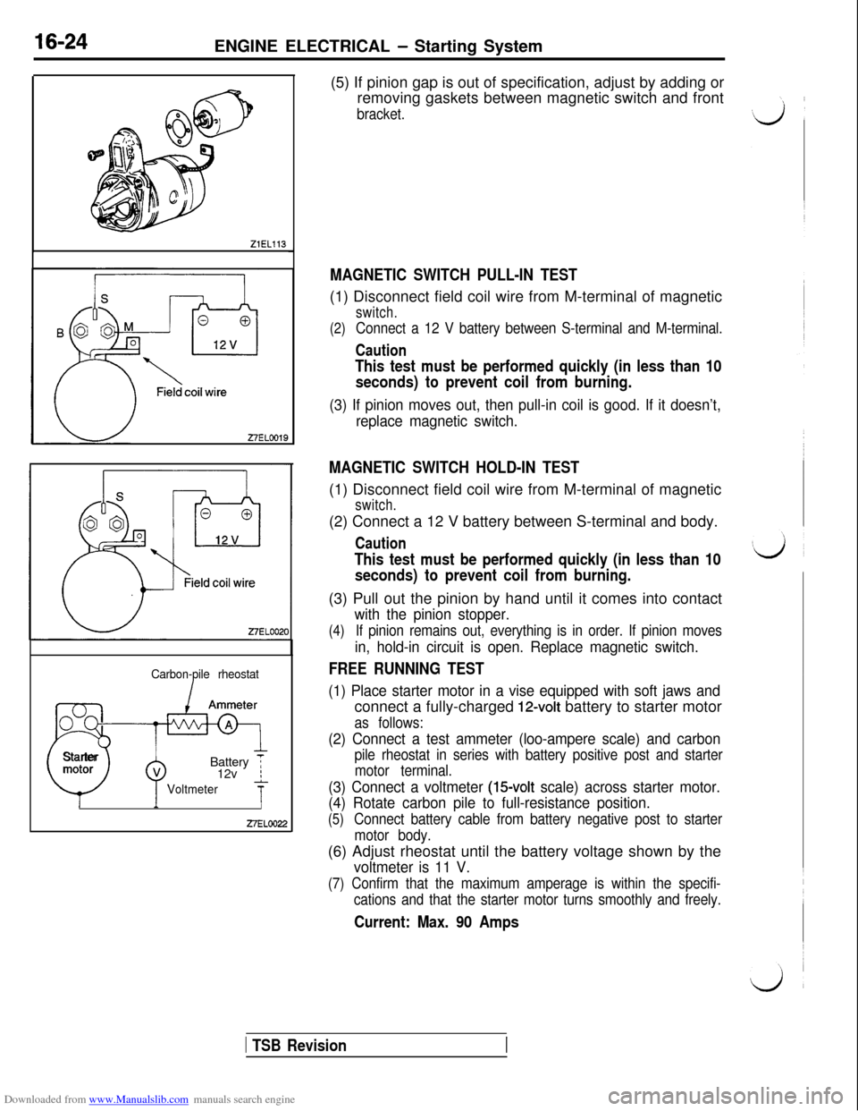
Voltmeter7-II27ELOO22(5) If pinion gap is out of specification, adjust by adding or
removing gaskets between magnetic switch and front
bracket.
MAGNETIC SWITCH PULL-IN TEST(1) Disconnect field coil wire from M-terminal of magnetic
switch.
(2)
Connect a 12 V battery between S-terminal and M-terminal.
Caution
This test must be performed quickly (in less than 10
seconds) to prevent coil from burning.
(3) If pinion moves out, then pull-in coil is good. If it doesn’t,
replace magnetic switch.
MAGNETIC SWITCH HOLD-IN TEST(1) Disconnect field coil wire from M-terminal of magnetic
switch.(2) Connect a 12 V battery between S-terminal and body.
Caution
This test must be performed quickly (in less than 10
seconds) to prevent coil from burning.(3) Pull out the pinion by hand until it comes into contact
with the pinion stopper.
(4)If pinion remains out, everything is in order. If pinion moves
in, hold-in circuit is open. Replace magnetic switch.
FREE RUNNING TEST
(1) Place starter motor in a vise equipped with soft jaws andconnect a fully-charged
12-volt battery to starter motor
as follows:
(2) Connect a test ammeter (loo-ampere scale) and carbon
pile rheostat in series with battery positive post and starter
motor terminal.
(3) Connect a voltmeter (15volt scale) across starter motor.
(4) Rotate carbon pile to full-resistance position.
(5)Connect battery cable from battery negative post to starter
motor body.(6) Adjust rheostat until the battery voltage shown by the
voltmeter is 11 V.
(7) Confirm that the maximum amperage is within the specifi-
cations and that the starter motor turns smoothly and freely.
Current: Max. 90 Amps
1 TSB Revision