switch MITSUBISHI 3000GT 1995 2.G User Guide
[x] Cancel search | Manufacturer: MITSUBISHI, Model Year: 1995, Model line: 3000GT, Model: MITSUBISHI 3000GT 1995 2.GPages: 738, PDF Size: 35.06 MB
Page 35 of 738
Downloaded from www.Manualslib.com manuals search engine L
iGENERAL
- How to Diagnose33
Power supply
Fuse
’ i
ON (2),----c//ISwitch
I
Motor
Z16AO260
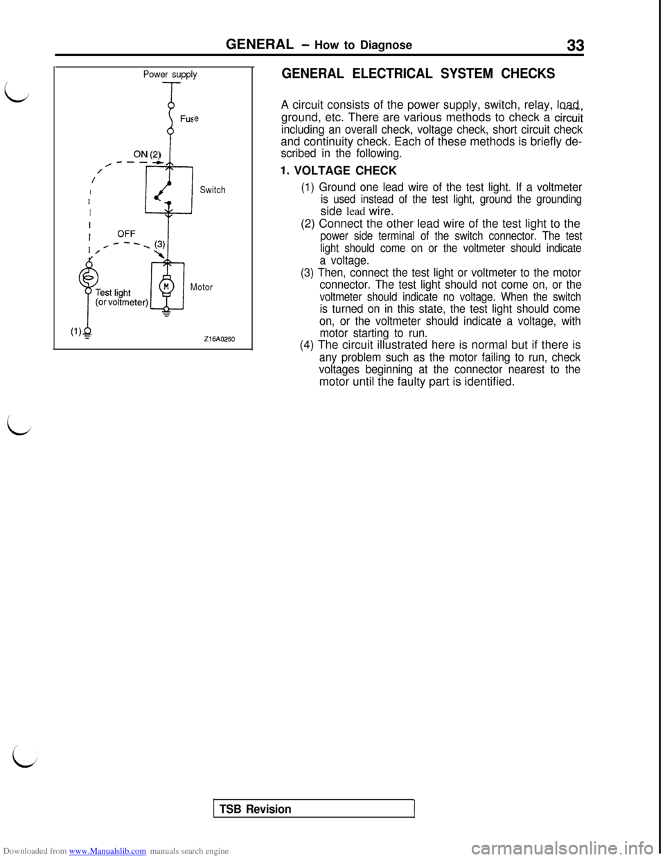
GENERAL ELECTRICAL SYSTEM CHECKSA circuit consists of the power supply, switch, relay, load
ground, etc. There are various methods to check a
circui;
including an overall check, voltage check, short circuit checkand continuity check. Each of these methods is briefly de-
scribed in the following.
1. VOLTAGE CHECK
(1) Ground one lead wire of the test light. If a voltmeter
is used instead of the test light, ground the groundingside lead wire.
(2) Connect the other lead wire of the test light to the
power side terminal of the switch connector. The test
light should come on or the voltmeter should indicate
a voltage.
(3) Then, connect the test light or voltmeter to the motor
connector. The test light should not come on, or the
voltmeter should indicate no voltage. When the switch
is turned on in this state, the test light should come
on, or the voltmeter should indicate a voltage, with
motor starting to run.(4) The circuit illustrated here is normal but if there is
any problem such as the motor failing to run, check
voltages beginning at the connector nearest to themotor until the faulty part is identified.
TSB Revision
Page 36 of 738
Downloaded from www.Manualslib.com manuals search engine GENERAL - How to Diagnose2. SHORT-CIRCUITS CHECK
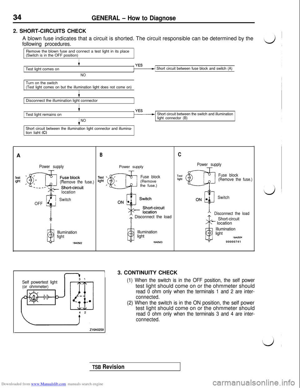
A blown fuse indicates that a circuit is shorted. The circuit responsible can be determined by the
following procedures.Remove the blown fuse and connect a test light in its place
(Switch is in the OFF position)
Test light comes on
+
NO
1 Short circuit between fuse block and switch (A)Turn on the switch
(Test light comes on but the illumination light does not come on)ItDisconnect the illumination light connector
I+Test light remains on
iNO
Short circuit between the illumination light connector and illumina-tion liaht ((3
Short circuit between the switch and illumination
light connector (B)A
Power supply
(Remove the fuse.)
1OFF
gi
location
Switch
a
Illuminationfight
16.4om2
BPower supply
Fuse block(Remove
the fuse.)
* Disconnect the load
iii
Illumination
light
T16Aom
13. CONTINUITY CHECK
Self powertest light
(or ohmmeter)
Z16AO269
C
Power supply
Test
lightFuse block
(Remove the fuse.)
Switch
Disconnect the load
ii
Short-circuit- location
Illumination
light
16Alncd?00000741
(1) When the switch is in the OFF position, the self powertest light should come on or the ohmmeter should
read 0 ohm only when the terminals 1 and 2 are inter-
connected.
(2) When the switch is in the ON position, the self powertest light should come on or the ohmmeter should
read 0 ohm only when the terminals 3 and 4 are inter-
connected.
TSB Revision
Page 42 of 738
Downloaded from www.Manualslib.com manuals search engine CONFIGURATION DIAGRAMS - Engine Compartment
A-69A-70
\ \
36FOO14
A-35
A-36
A-37
A-38
A-39
A-40
A-41
A-42
A-43
A-44A-72 A-71A-67+
A-5
A-57 A-55A-54 A-53 A-52 A-51A-47A-48
A-49
A-50
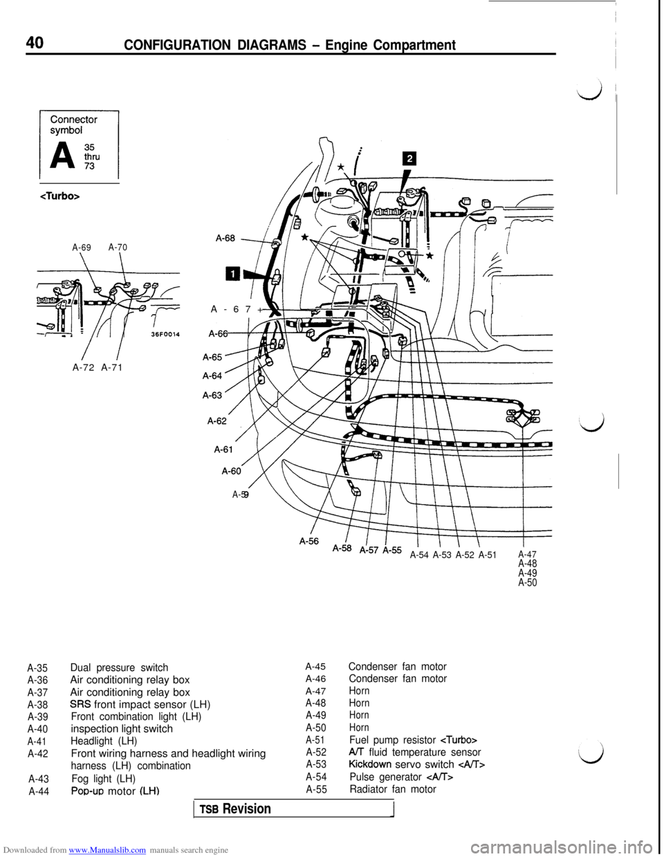
Dual pressure switchAir conditioning relay box
Air conditioning relay box
SW front impact sensor (LH)
Front combination light (LH)inspection light switch
Headlight (LH)Front wiring harness and headlight wiring
harness (LH) combination
Fog light (LH)
POWJO motor (LH)A-45
A-46
A-47
A-48
A-49
A-50
A-51
A-52
A-53
A-54
A-55
Condenser fan motor
Condenser fan motor
Horn
Horn
Horn
Horn
Fuel pump resistor
A/T fluid temperature sensor
Kickdown servo switch GAIT>
Pulse generator
Radiator fan motor
TSB Revision
Page 43 of 738
Downloaded from www.Manualslib.com manuals search engine CONFIGURATION DIAGRAMS - Engine CompartmentENGINE
HOOD
A-73
\
/I IIA-46 A-45 A-44
A-43A-42
A-56
A-57A-58
A-59
A-60
A-61A-62
A-63
A-64
A-65
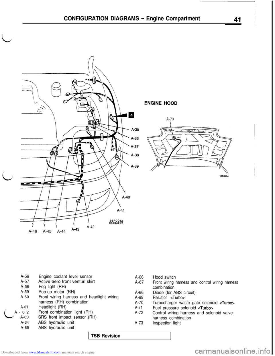
Engine coolant level sensorActive aero front venturi skirt
Fog light (RH)
Pop-up motor (RH)
Front wiring harness and headlight wiring
harness (RH) combination
Headlight (RH)
Front combination light (RH)
SRS front impact sensor (RH)
ABS hydraulic unit
ABS hydraulic unit
A-66Hood switch
A-67
Front wiring harness and control wiring harness
combination
A-66
Diode (for ABS circuit)
A-69
Resistor
A-70
Turbocharger waste gate solenoid
A-71
Fuel pressure solenoid
A-72
Control wiring harness and solenoid valve
harness combination
A-73
Inspection light
TSB Revision
Page 46 of 738
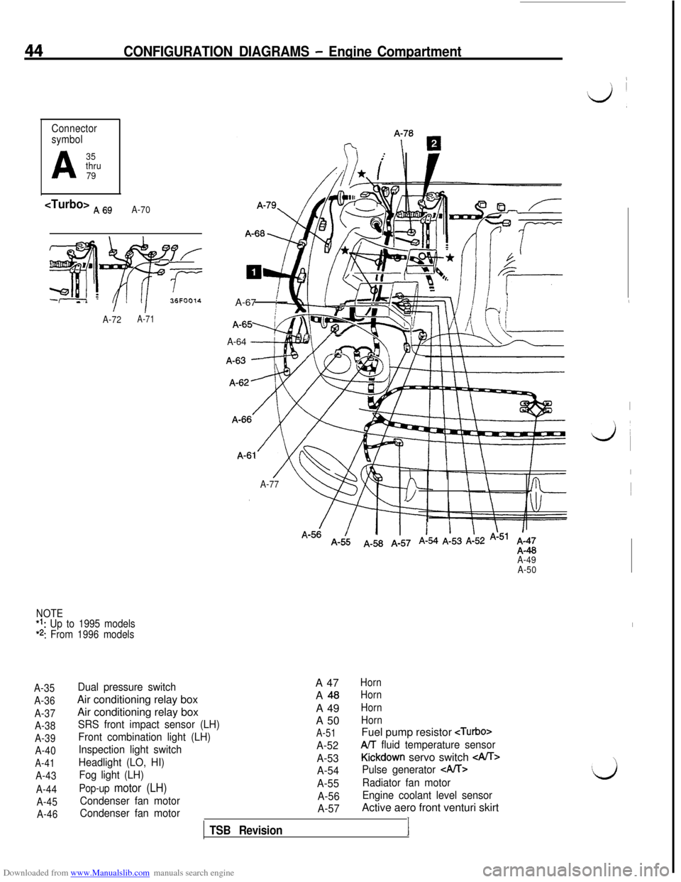
Downloaded from www.Manualslib.com manuals search engine 44CONFIGURATION DIAGRAMS - Engine Compartment
Connector
symbol
A
35
thru
79
36FOOl4
A-72A-71A-67
:
A-64 --+py>
A-77\ \
A-49
A-50
NOTE*t: Up to 1995 models*2: From 1996 models
A-35
A-36
A-37
A-38
A-39
A-40
A-41
A-43
A-44
A-45
A-46
Dual pressure switchAir conditioning relay box
Air conditioning relay box
SRS front impact sensor (LH)
Front combination light (LH)
Inspection light switch
Headlight (LO, HI)
Fog light (LH)
Pop-up motor (LH)
Condenser fan motor
Condenser fan motor
TSB RevisionA 47
HornA
48HornA 49
HornA 50
Horn
A-51Fuel pump resistor
A-52AIT fluid temperature sensor
A-53
Kickdown servo switch
A-54Pulse generator CA/T>
A-55Radiator fan motor
A-56Engine coolant level sensor
A-57Active aero front venturi skirt
I
,
‘d ,
,
I
k&i
I1
I
Page 47 of 738
Downloaded from www.Manualslib.com manuals search engine CONFIGURATION DIAGRAMS - Engine Compartment45
; !i i\1 ._’ !\\-7’I \ ‘\
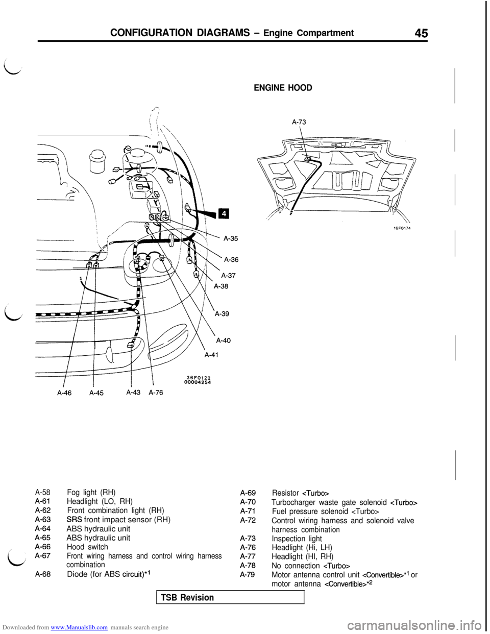
A-58
A-61A-62A-63A-64A-65A-66A-67A-66
A-46A-45A-43 A-76
Fog light (RH)
Headlight (LO, RH)
Front combination light (RH)
SRS front impact sensor (RH)
ABS hydraulic unit
ABS hydraulic unit
Hood switch
Front wiring harness and control wiring harness
combinationDiode (for ABS
circuit)*’
ENGINE HOOD
A-73A-69A-70
A-71A-72A-73A-76A-77A-78
A-79
Resistor
Turbocharger waste gate solenoid
Fuel pressure solenoid
Control wiring harness and solenoid valve
harness combination
Inspection light
Headlight (Hi, LH)
Headlight (HI, RH)
No connection
Motor antenna control unit cConvertible>*1 or
motor antenna
4onvertible>*2
TSB Revision
Page 48 of 738
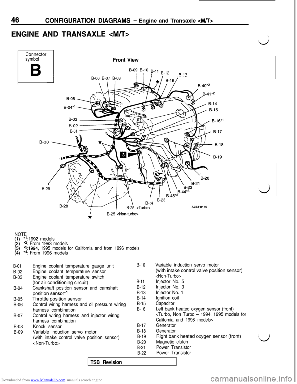
Downloaded from www.Manualslib.com manuals search engine 46CONFIGURATION DIAGRAMS - Engine and Transaxle
ENGINE AND TRANSAXLE
Connector
symbol
B
Front View
B-0: B;lO 53-11B-12R-i?
IB-06 B-07 B-08B-40*’
B-02
------+
B-01B-30
\ 7
I
B-29
- \B-:4B-23
B-25
A36F0176
B-01
B-02
B-03
B-04
B-05
B-06
B-07
B-08
B-09
i*B-25
NOTE
[:I*‘A992 models*2: From 1993 models*s:1994, 1995 models for California and from 1996 models*4: From 1996 models
Engine coolant temperature gauge unit
Engine coolant temperature sensor
Engine coolant temperature switch(for air conditioning circuit)
Crankshaft position sensor and camshaftposition
sensor*’Throttle position sensor
Control wiring harness and oil pressure wiring
harness combination
Control wiring harness and injector wiring
harness combination
Knock sensor
Variable induction servo motor
(with intake control valve position sensor)
B-10
B-11
B-12
B-13
B-14
B-15
B-16
B-17
B-18
B-19
B-20
B-21
B-22
Variable induction servo motor(with intake control valve position sensor)
Injector No. 5
Injector No. 3
Injector No. 1
Ignition coil
Capacitor
Left bank heated oxygen sensor (front)
California and 1996 models>
Generator
GeneratorRight bank heated oxygen sensor (front)
Magnetic clutch
Power Transistor
Power TransistorL)
TSB Revision
Page 49 of 738
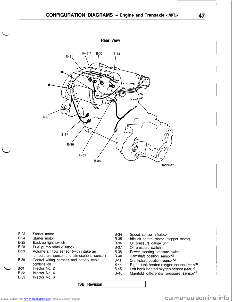
Downloaded from www.Manualslib.com manuals search engine B-23
B-24
B-25
B-28
B-29
B-30
B-31
B-32
B-33
Rear View
B-46*4
B-32
B-33
A36F0167
Starter motor
Starter motor
Back-up light switchFuel pump relay
temperature sensor and atmospheric sensor)
Control wiring harness and battery cable
combination
Injector No. 2
Injector No. 4
Injector No. 6
B-34
B-35
B-36
B-37
B-38
B-40
B-41
B-44
B-45B-46
Speed sensor
Idle air control motor (stepper motor)
Oil pressure gauge unit
Oil pressure switch
Power steering pressure switch
Camshaft position
sensor*2
Crankshaft position sensor*2Right bank heated oxygen sensor
(rear)*3Left bank heated oxygen sensor
(rear)*3Manifold differential pressure
sensor*4
CONFIGURATION DIAGRAMS - Engine and Transaxle
TSB Revision
Page 50 of 738
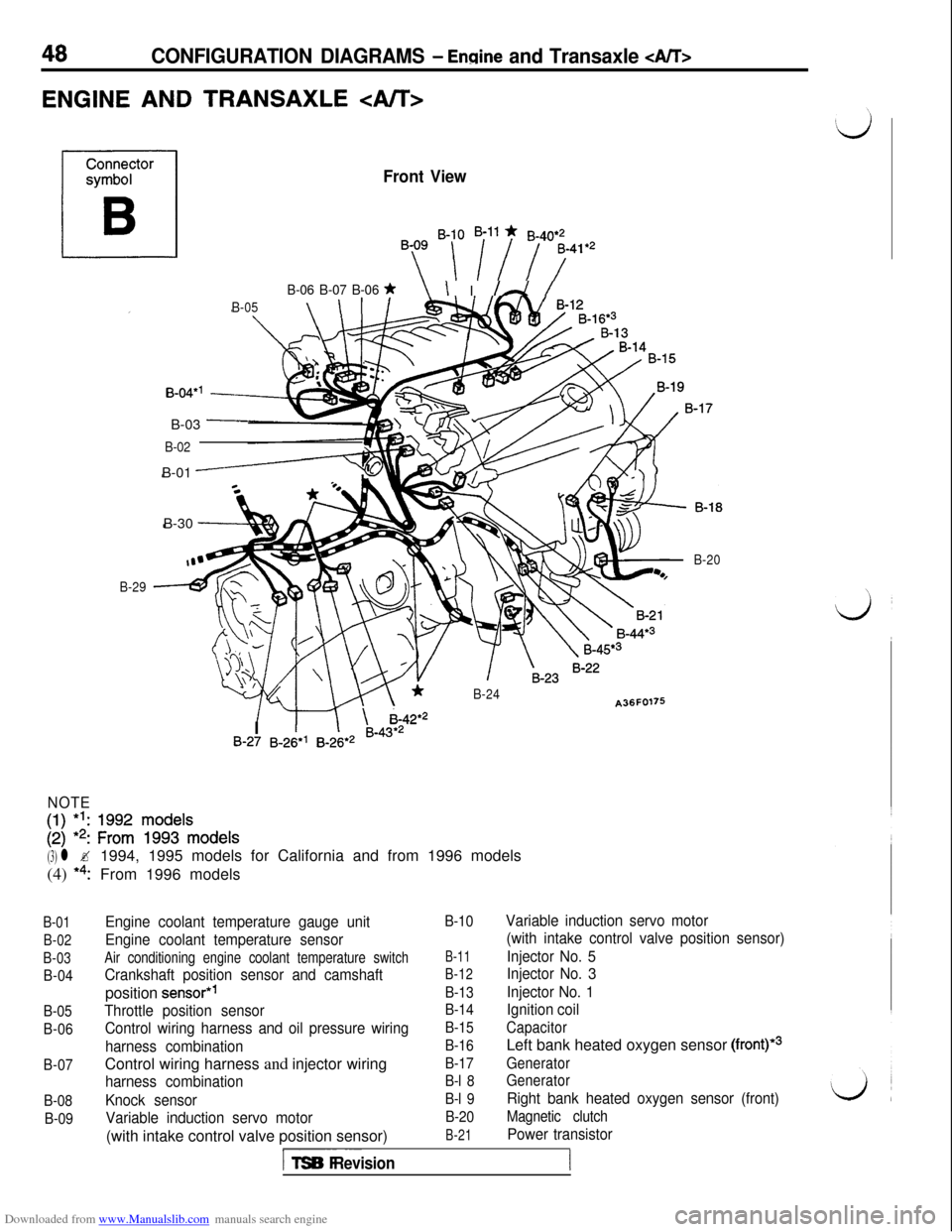
Downloaded from www.Manualslib.com manuals search engine 48CONFIGURATION DIAGRAMS - Ennine and Transaxle
ENGINE AND TRANSAXLE
Front View
By ‘-[ i”i 7741e2
B-06 B-07 B-06 *\ I I /A /
B-05\ \IB-30
-
B-04*’B-03
-
B-02B-01
-
B-29
*B-24A36F0176
/ m \ i-42*2
B-20I
1IB-27 B-26*’ B-26*2 B-43*2
NOTE
[:I 1:: zif ~$$‘~ode~s
(3) l ?1994, 1995 models for California and from 1996 models
(4)
*4:From 1996 models
B-01
B-02
B-03
B-04
B-05
B-06
B-07
B-08
B-09
Engine coolant temperature gauge unit
Engine coolant temperature sensor
Air conditioning engine coolant temperature switch
Crankshaft position sensor and camshaftposition
sensor*’
Throttle position sensor
Control wiring harness and oil pressure wiring
harness combinationControl wiring harness and injector wiring
harness combination
Knock sensor
Variable induction servo motor(with intake control valve position sensor)
B-10
B-11
B-12
B-13
B-14
B-15
B-16
B-17
B-l 8
B-l 9
B-20
B-21
Variable induction servo motor
(with intake control valve position sensor)
Injector No. 5
Injector No. 3
Injector No. 1
Ignition coil
CapacitorLeft bank heated oxygen sensor
(front)*3
Generator
Generator
Right bank heated oxygen sensor (front)
Magnetic clutch
Power transistor
I-- ~~~TSB Revision
Page 51 of 738
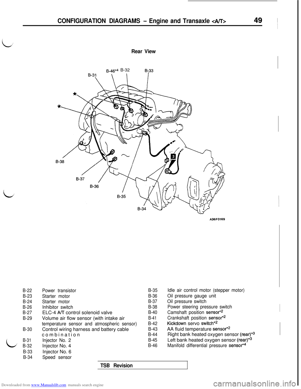
Downloaded from www.Manualslib.com manuals search engine B-22
B-23
B-24
B-26
B-27
B-29
B-30
B-31
B-32
B-33
B-34
Rear View
B-46*4 B-328~33
CONFIGURATION DIAGRAMS - Engine and Transaxle 49 ~
I
A36F0169
Power transistor
Starter motor
Starter motor
Inhibitor switchELC-4
A/T control solenoid valve
Volume air flow sensor (with intake air
temperature sensor and atmospheric sensor)Control wiring harness and battery cable
combination
Injector No. 2Injector No. 4
Injector No. 6
Speed sensor
B-35
B-36
B-37
B-38
B-40
B-41
B-42
B-43
B-44
B-45
B-46
Idle air control motor (stepper motor)
Oil pressure gauge unit
Oil pressure switch
Power steering pressure switch
Camshaft position
sensor*2
Crankshaft position sensor*2
Kickdown servo switch*2AA fluid temperature
sensor*2Right bank heated oxygen sensor
(rear)*3Left bank heated oxygen sensor
(rear)*3
Manifold differential pressure sensor*4
TSB Revision