Panel MITSUBISHI 3000GT 1995 2.G Owner's Guide
[x] Cancel search | Manufacturer: MITSUBISHI, Model Year: 1995, Model line: 3000GT, Model: MITSUBISHI 3000GT 1995 2.GPages: 738, PDF Size: 35.06 MB
Page 504 of 738
Downloaded from www.Manualslib.com manuals search engine 54-8CHASSIS ELECTRICAL - Ignition Switch
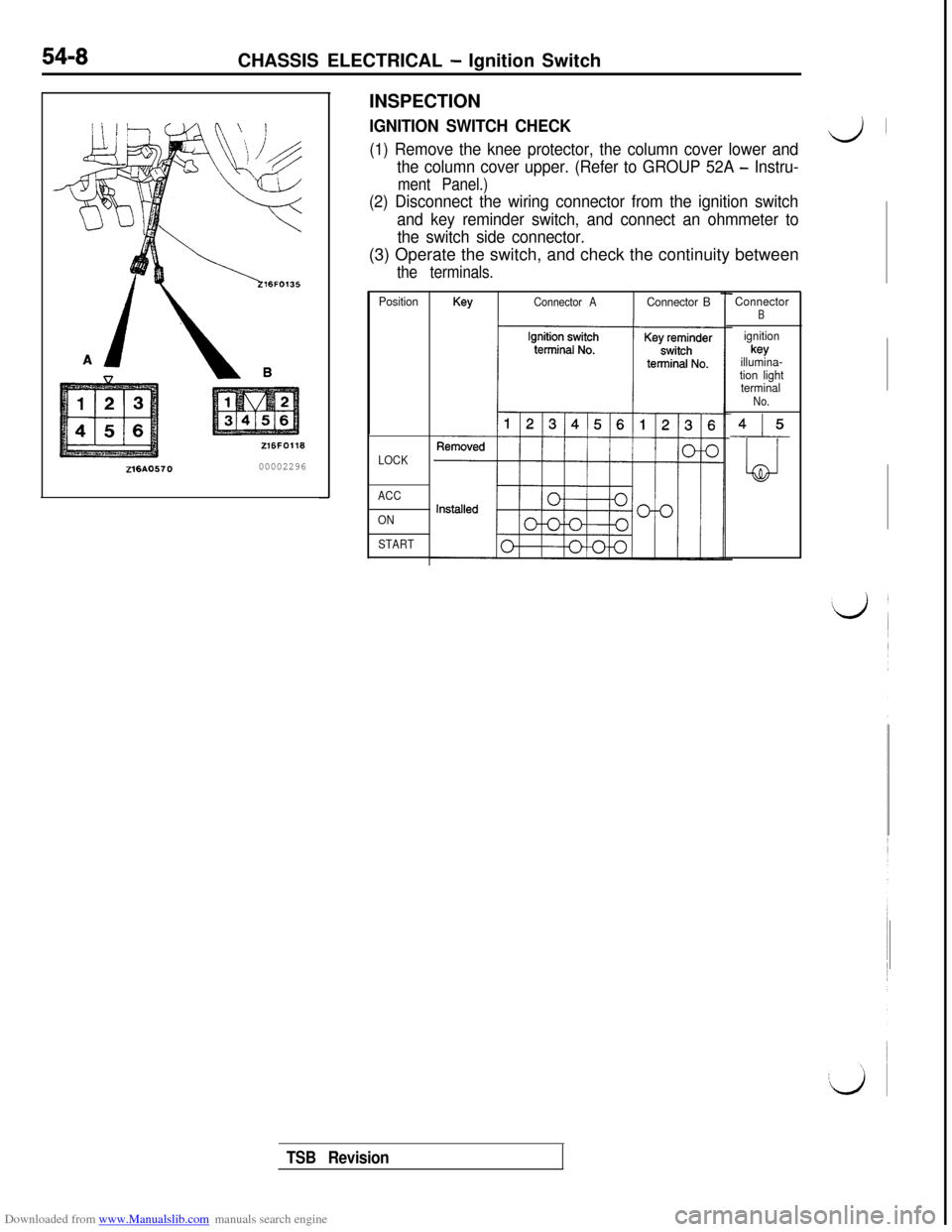
216AO57000002296INSPECTION
IGNITION SWITCH CHECK
(1) Remove the knee protector, the column cover lower andd’
the column cover upper. (Refer to GROUP 52A - Instru-
ment Panel.)
(2) Disconnect the wiring connector from the ignition switch
and key reminder switch, and connect an ohmmeter to
the switch side connector.(3) Operate the switch, and check the continuity between
the terminals.
PositionKeyConnector AConnector B
LOCK
ACC
ON
START
ConnectorB
ignitionkey
illumina-
tion light
terminal
No.
415
LJ
TSB Revision
Page 529 of 738
Downloaded from www.Manualslib.com manuals search engine CHASSIS ELECTRICAL - Meters and Gauges
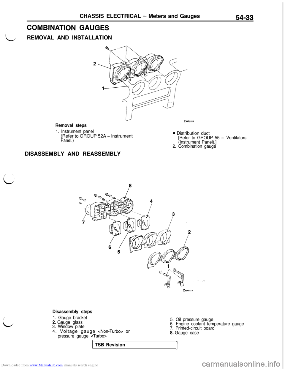
COMBINATION GAUGESREMOVAL AND INSTALLATION
54-33
Removal steps
1. Instrument panel(Refer to GROUP 52A
- InstrumentPanel.)
0 Distribution duct[Refer to GROUP 55 - Ventilators
(Instrument Panel).]
2. Combination gaugeDISASSEMBLY AND REASSEMBLY
i;
Disassembly steps
1. Gauge bracket2. Gauge glass
3. Window plate4. Voltage gauge
pressure gauge
5. Oil pressure gauge
6. Engine coolant temperature gauge
7. Printed-circuit board
8. Gauge caseTSB Revision
J
Page 606 of 738
Downloaded from www.Manualslib.com manuals search engine 54-110CHASSIS ELECTRICAL - Lighting System
1
16FO121
16FO12600002396
I‘VA1 I\ Air outlet assembly _I
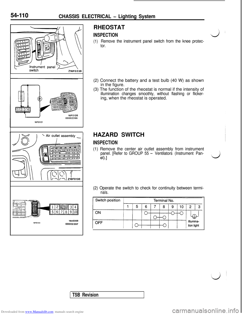
RHEOSTAT\
INSPECTIONJL
(1)Remove the instrument panel switch from the knee protec-
tor.(2) Connect the battery and a test bulb (40 W) as shown
in the figure.
(3) The function of the rheostat is normal if the intensity of
illumination changes smoothly, without flashing or flicker-ing, when the rheostat is operated.
HAZARD SWITCH
INSPECTION
(1) Remove the center air outlet assembly from instrument
panel. [Refer to GROUP 55 - Ventilators (Instrument Pan-’
eO.1d
(2) Operate the switch to check for continuity between termi-
nals.
TSB Revision
Page 609 of 738
Downloaded from www.Manualslib.com manuals search engine L
L
CHASSIS ELECTRICAL - Column Switch54-113
Front of vehicles
219FOlZ:
Mating mark-! !kU19FOOE
-
16FO237
16FO1:900002398
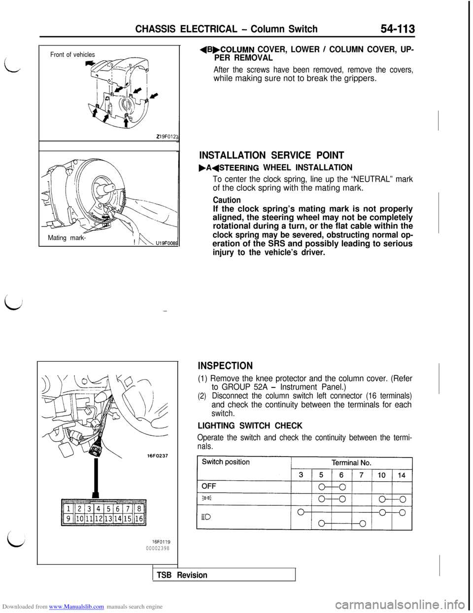
+B,COLUMN COVER, LOWER / COLUMN COVER, UP-
PER REMOVAL
After the screws have been removed, remove the covers,while making sure not to break the grippers.
INSTALLATION SERVICE POINT
.A(STEERING WHEEL INSTALLATION
To center the clock spring, line up the “NEUTRAL” markof the clock spring with the mating mark.
CautionIf the clock spring’s mating mark is not properly
aligned, the steering wheel may not be completely
rotational during a turn, or the flat cable within the
clock spring may be severed, obstructing normal op-eration of the SRS and possibly leading to serious
injury to the vehicle’s driver.
INSPECTION
(1) Remove the knee protector and the column cover. (Refer
(2)
to GROUP 52A - Instrument Panel.)
Disconnect the column switch left connector (16 terminals)
and check the continuity between the terminals for each
switch.
LIGHTING SWITCH CHECK
Operate the switch and check the continuity between the termi-
nals.
TSB Revision
Page 674 of 738
Downloaded from www.Manualslib.com manuals search engine 54-178CHASSIS ELECTRICAL - Radio and TaDe Plaver
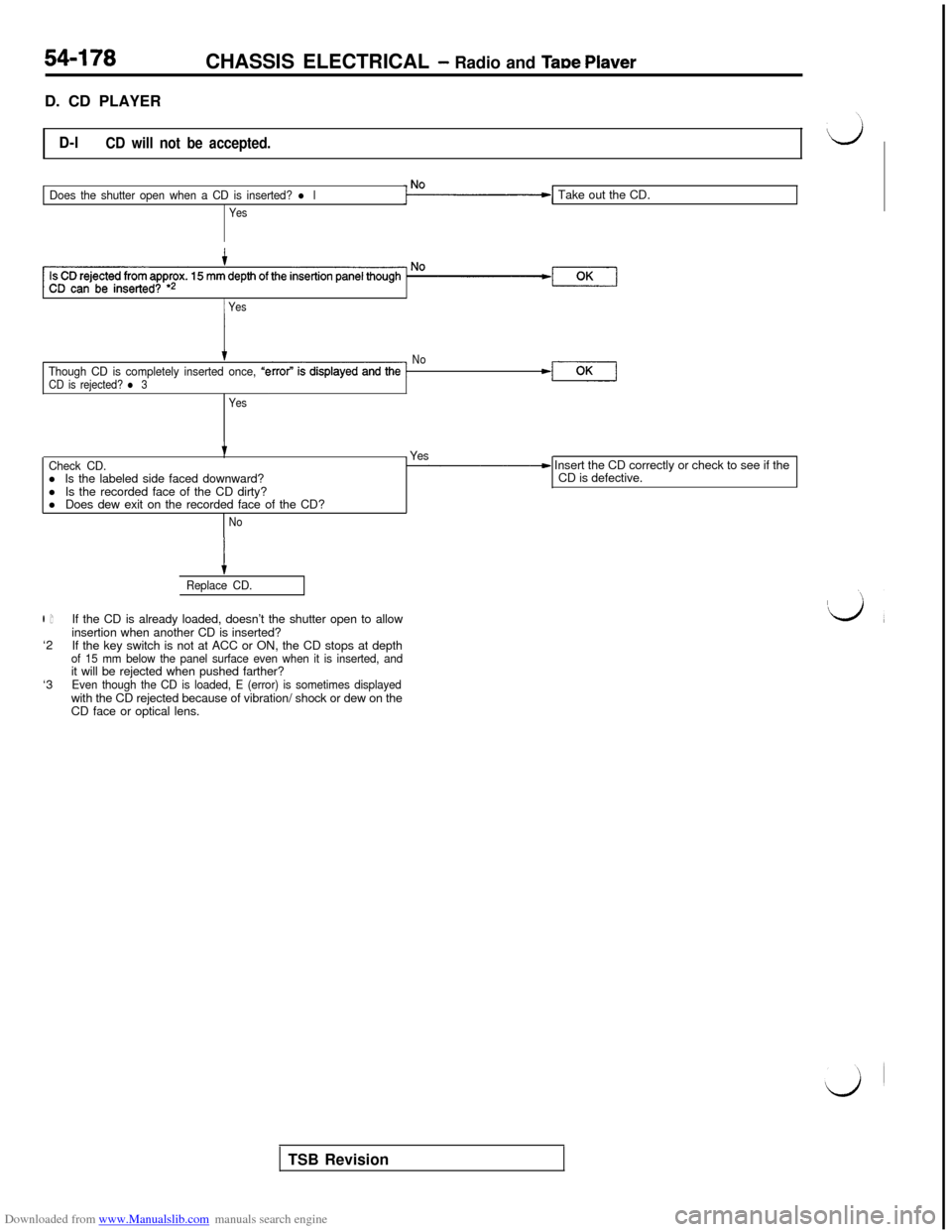
D. CD PLAYER
D-lCD will not be accepted.
Does the shutter open when a CD is inserted? l l
YesTake out the CD.
1 Yes
tThough CD is completely inserted once, “e
CD is rejected? l 3No-l
Yes
tCheck CD.l Is the labeled side faced downward?
l Is the recorded face of the CD dirty?
l Does dew exit on the recorded face of the CD?- Yes- Insert the CD correctly or check to see if the
CD is defective.
No
l 1‘2
‘3
tReplace CD.If the CD is already loaded, doesn’t the shutter open to allow
insertion when another CD is inserted?
If the key switch is not at ACC or ON, the CD stops at depth
of 15 mm below the panel surface even when it is inserted, andit will be rejected when pushed farther?
Even though the CD is loaded, E (error) is sometimes displayedwith the CD rejected because of vibration/ shock or dew on the
CD face or optical lens.
TSB Revision
Page 679 of 738
Downloaded from www.Manualslib.com manuals search engine CHASSIS ELECTRICAL - Radio- and TaDe Plaver54-183
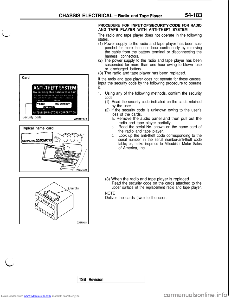
Card
Security code216N1034
Typical name card
A Cards
PROCEDURE FOR INPUTOFSECURITYCODE FOR RADIOAND TAPE PLAYER WITH ANTI-THEFT SYSTEM
The radio and tape player does not operate in the following
states.
(1) Power supply to the radio and tape player has been sus-
pended for more than one hour continuously by removing
the cable from the battery terminal or disconnecting the
harness connectors.
(2) The power supply to the radio and tape player has been
suspended for more than one hour owing to blown fuse
or discharged battery.(3) The radio and tape player has been replaced.
If the radio and tape player does not operate for these causes,
input the security code by the following procedure to operate
it.
1.Using any of the following methods, confirm the security
code.
(1)
Read the security code indicated on the cards retained
by the user.
(2) If the security code is unknown owing to the user’s
loss of the cards,a. Remove the audio panel and then pull out the
radio and tape player partially.
b.Read the serial No. shown on the name card of
the radio and tape player.
c.Look up the anti-theft code corresponding to the
serial number in the serial number-anti-theft code
table; or, make inquiries to Mitsubishi Motor Sales
of America, Inc.(3) When the radio and tape player is replaced
Read the security code on the cards attached to the
upper surface of the replacement radio and tape player.
NOTE
Deliver the cards (two) to the user.
TSB Revision
Page 682 of 738
Downloaded from www.Manualslib.com manuals search engine 54-186
CHASSIS ELECTRICAL - Radio and Tape Player
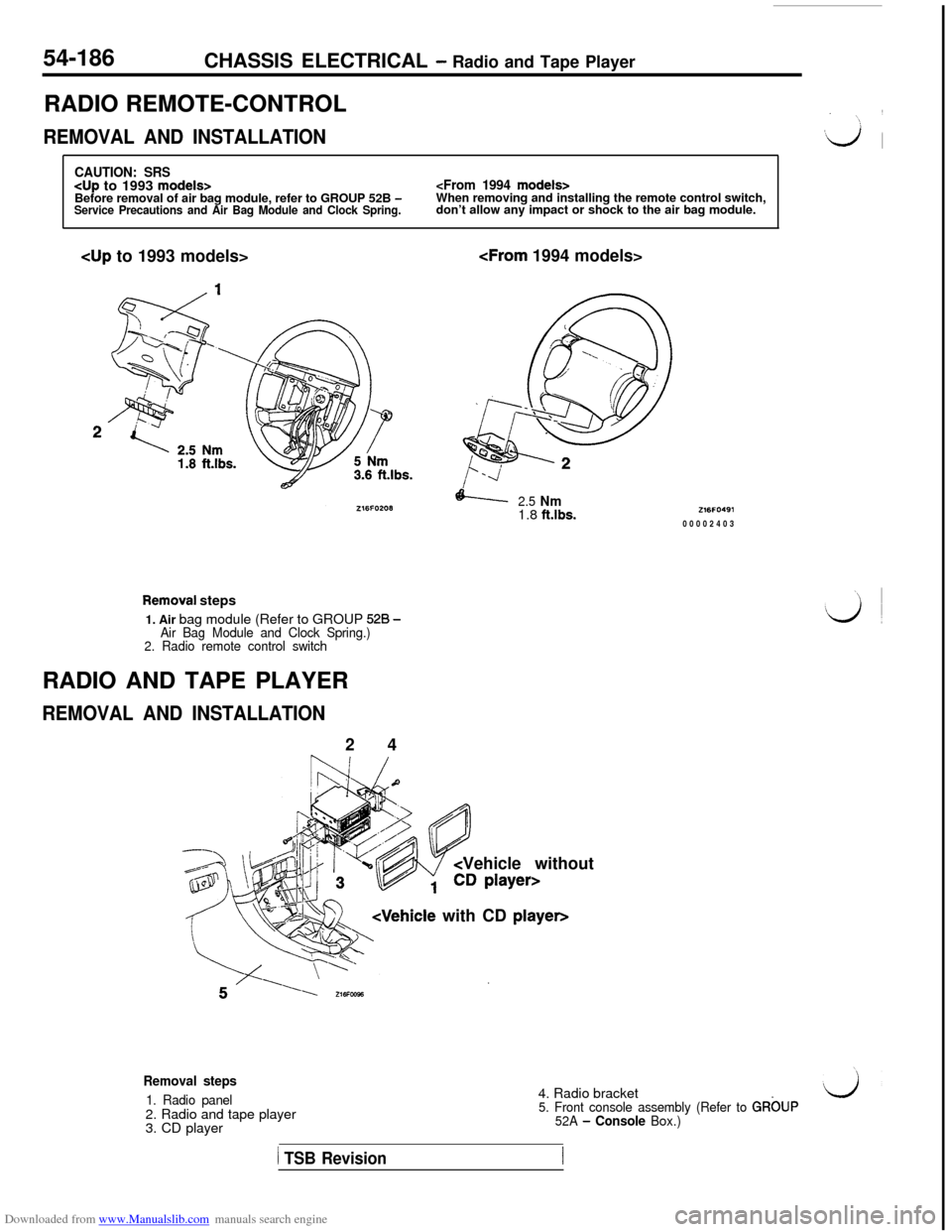
RADIO REMOTE-CONTROL
REMOVAL AND INSTALLATION
CAUTION: SRS
don’t allow any impact or shock to the air bag module.cup to 1993 models>
2.5 Nm1.8 ft.lbs.
Removai steps
1. Air bag module (Refer to GROUP
528 -Air Bag Module and Clock Spring.)
2. Radio remote control switchRADIO AND TAPE PLAYER
REMOVAL AND INSTALLATION2 4
Vehicle without
Z16FO49100002403
Removal steps
1. Radio panel2. Radio and tape player
3. CD player4. Radio bracket5. Front console assembly (Refer to GRbUP
52A - Console Box.)
1 TSB Revision
Page 731 of 738
Downloaded from www.Manualslib.com manuals search engine ALPHABETICAL INDEX1
A
iiABSPOWER RELAY, Check . . . . . . . . . . . . . . . . . . . . , . . .
35-82-lRELAY.............................................35-110-1SIGNAL, On-vehicle Inspection.................13A-176,277-iACCELERATOR
CABLE..............................................
17-4-l
SWITCH
ACTIVE AERO SYSTEM, Check.........................
51-7-l
ACTIVE EXHAUST
CONTROL UNIT, On-vehicle Inspection..........13A-173,274-lSYSTEM............................................15-40-l
AERO PARTS........................................51-19-lAIR BAG..........................................520-74-lMODULE......................................528-82, 87-lAIR CLEANER.........................................15-9-l
ELEMENT, Maintenance..............................00-45-lAIR CONDITIONING...................................55-3-l
55-18-lCONTROL PANEL...................................55-73-lCONTROL UNIT.....................................55-73-lENGINE COOLANT TEMPERATURE SWITCHEngine Cooling.....................................14-13-l
ASSIST LINK
Maintenance
.........................................00-49-IAXLE
Rear
HUB, Rear -&VD>
....................................
27-4-lSHAFT
B
BALL JOINT SEALS, Maintenance. . . .
BAROMETRIC PRESSURE SENSOR
On-vehicle Inspection . . . . . . . . . . . .BASIC IDLE SPEED, Adjustment . . . . . .
BATTERY . . . . . . . . . . . . . . . . . . . . . . . . . .
Discharged, Remedy . . . . . . . . . . . .
BELT LOCK CONTROLLER . . . . . . . . .
BLOWER. . . . . . . . . . . . . . . . . .
BOOSTER, Clutch
Parking. . . . . . . . . . ..*.............
BOOSTER . . . . . . . . . . . . . . . .
Operating Check . . . . . . . . . . . . . . . .
. . . . . . . . . . . . . . . .00-52-l
..........13A-91,217-l..............
13A-55-l................64-3-11................35-82-l............55-32,74-t................
55-35-l.................21-6-l.........13A-171,273-l
.................36-8-l................35-87-l................35-64-l
DISC..........................................35-93,103-l
Front, Check.......................................35-70-IRear, Check........................................35-73-lFLUID LEVEL SENSOR, Check........................35-64-l
HOSES, Maintenance.................................00-52-I
LINE................................................35-91-lLINING.............................................35-74-lPAD
Disc, Front.........................................
35-66-l
Disc, Rear.............~..................>..........35-71-lPEDAL.............................................35-84-l
Check and Adjustment......................
:........35-63-lBUMPERFront...............................................51-8-lRear...............................................51-13-l
CAMSHAFT
OIL SEALS..........................................
11-21-lPOSITION SENSOR, On-vehicle Inspection......13A-103,225-lCATALYTIC CONVERTER..............................17-71-l
..........................................
15-33-lCD AUTO CHANGER................................54-191-11CENTER PILLAR GLASS..............................42-33-l
CENTRAL DOOR LOCKING SYSTEM...................42-49-lCHARGE AIR COOLER................................15-11-l
CHARGING SYSTEM..................................l.6-2-11CIGARETTE LIGHTER..............................54-123-k
CLOCK SPRING, SRS..............................528-74-I
CLOSED THROTTLE POSITION SWITCH
Adjustment.......................................
13A-57-lOn-vehicle Inspection.........................13A-101,223-lCLUTCH
BOOSTER OPERATING, Check
MASTER CYLINDER.................................21-14-lPEDAL..............................................21-8-lCheck and Adjustment................................21-5-l
RELEASE CYLINDER................................21-16-IVACUUM LINE cAWD>...............................21-18-I
COLUMN SWITCH..................................54-112-11COMBINATION GAUGES.............................54-33-kCOMBINATION LIGHT...............................54-106-11COMBINATION METERS.............................54-31-11COMPRESSOR CLUTCH RELAY,On-vehicle Inspection...........................13A-123,236-lCONDENSER
Active Exhaust, On-vehicle Inspection...........13A-173,274-lECS.............................................338-20-I
Electronic CABS>..................................35-119-l
CONTROL VALVE.....................................37B-9-l
Fuel Tank Pressure..................................13F-6-IInspection..
........................................17-65-l
CRANKSHAFT
FRONT OIL SEAL....................................
11-25-lPOSITION SENSOR, On-vehicle Inspection......13A-107,227-l
REAR QIL SEAL.....................................11-26-l
Page 733 of 738
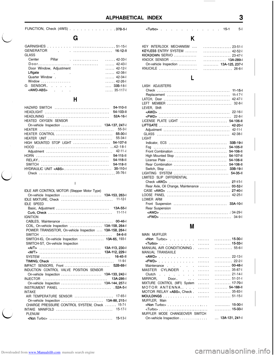
Downloaded from www.Manualslib.com manuals search engine ALPHABETICAL INDEX3FUNCTION, Check (4WS) .
. . . . . . . . . . . .37B-5-l
GARNISHES . . . . . . . . .
GENERATOR . .
GLASSCenter Pillar .
Door.....................
Door Window, Adjustment
Liftgate . .Quarter Window.Window. . . . . . . . . . . . . . . .G SENSOR.. . . . . .
G
.........................51-15-l........................16-12-11
.....................42-33-l.....................42-43-l......42-12-l......42-38-l......42-34-l......42-26-l....338-l 8-l.....35-117-l
H
HAZARD SWITCH..................................54-110-11
HEADLIGHT........................................54-103-11
HEADLINING.......................................52A-16-l
HEATED OXYGEN SENSOROn-vehicle Inspection.........................13A-137,247-l
HEATER..............................................55-3-l
HEATER CONTROL...................................55-30-I
HEATER UNIT........................................55-34-l
HIGH MOUNTED STOP LIGHT.......................54-107-11
HOOD...............................................42-18-lAdjustment.........................................42-11 -I
HORN.............................................54-115-11RELAY..
..........................................54-118-11
SWITCH..........................................54-118-11
HYDRAULIC UNIT CABS>.............................35-110-I
Check
.............................................35-76-lI
IDLE AIR CONTROL MOTOR (Stepper Motor Type)
On-vehicle Inspection.........................13A-153,263-l
IDLE MIXTURE, Check................................11-12-l
IDLE SPEED
Basic, Adjustment.................................13A-55-lCurb,Check........................................11-11-l
IGNITION
CABLES, Maintenance................................00-46-l
COIL, On-vehicle Inspection....................
13A-158,264-l
POWER TRANSISTOR, On-vehicle Inspection....13&158,264-l
SWITCH............................................54-6-11
SWITCH-IG, On-vehicle Inspection...............13A-65, 193-l
SWITCH-ST, On-vehicle Inspection
......................................13A-113,230-l
SYSTEM...........................................16-45-11
TIMING,‘Check.......................................11-9-l
IMPACT SENSORS, Front............................528-68-I
INDUCTION CONTROL VALVE POSITION SENSOROn-vehicle Inspection.........................13A-133,242-l
INJECTOR........................................13A-286-l
On-vehicle Inspection.........................
13A-144,257-l
INSTRUMENT PANEL.................................52A-5-lINTAKE
AIR TEMPERATURE SENSOR........................17-65-l
On-vehicle Inspection..........................13A-88,215-l
CHARGE PRESSURE CONTROL SYSTEM, Check.......15-7-l
INTAKE MANIFOLD...................................15-17-l
PLENUM
K
KEY INTERLOCK MECHANISM....KEYLESS ENTRY SYSTEM........KICKDOWN SERVO...............KNOCK SENSOR.................On-vehicle Inspection............KNUCKLE........................
.................23-51-l.................42-52-l.................23-47-l..............13A-289-l..........
13A-125,237-l..................26-6-l
L
LASH ADJUSTERSCheck.............................................11-15-lReplacement.......................................11-l 7-l
LATCH, Door.........................................42-47-lLEFT MEMBER........................................32-8-l
LEVER, Shift
cFWD>.............................................22-8-lLICENSE PLATE LIGHT.............................54-106-11
LIFTGATE............................................42-20-I
Adjustment.........................................42-11-l
GLASS.............................................42-38-lLIGHT
Indicator, ECS....................................338-19-IFog.............................................54-105-11Front Combination.................................54-106-11High Mounted Stop................................54-107-11License Plate.....................................54-106-11
Rear Combination.................................54-106-11Switch, Stop......................................33B-19-l
LIGHTING SYSTEM..................................54-35-11LIMITED SLIP DIFFERENTIALCheck cAWD>......................................27-l 5-l
Rear Axle, Oil Change, Maintenance...................00-52-I
CASE
LOOSE PANEL.......................................42-25-l
LOWER ARM
Front Suspension.................................33A-10-I
Rear Suspension
M
MAIN MUFFLER
MANUAL AIR CONDITIONING .
MANUAL TRANSAXLE
cFWD> . . . . . . . . . . . .Maintenance. . . . .
MASTER CYLINDER . . .
Clutch . . . . . . . .
MIRROR, Door..
_. .MIXTURE CONTROL (MFI) SystemMOTOR ANTENNA.. . . .
MOTOR RELAY
CABS>, Check .MOULDINGS . . . . . . . . . . . . .MUFFLER, Main
.....................
.......
...............................................................
..........15-30-I..........
15-33-l...........55-6-l..........
22-13-l...........22-2-l..........00-48-I..........35-87-l..........21-14-l..........51-31-l..........17-70-I........54-188-11..........35-83-l..........51-15-l...........
15-30-I..........15-33-l...
13A-131,241-l
Page 735 of 738
Downloaded from www.Manualslib.com manuals search engine ALPHABETICAL INDEX5
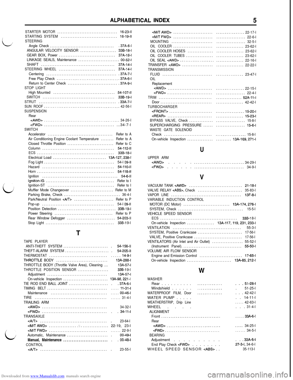
STARTER MOTOR...................................16-23-11STARTING SYSTEM.................................16-19-11
STEERINGAngle Check.........................................37A-6-l
ANGULAR VELOCITY SENSOR.....................338-18-l
GEAR BOX, Power.................................37A-18-l
LINKAGE SEALS, Maintenance........................00-52-I
SHAFT...........................................37A-14-I
STEERING WHEEL.................................37A-14-l
Centering..........................................37A-7-l
Free Play Check
....................................37A-6-l
Return to Center Check..............................37A-9-lSTOP LIGHTHigh Mounted....................................54-107-11SWITCH..........................................338-19-ISTRUT..............................................33A-7-lSUN ROOF...........................................42-56-l
SUSPENSION
RearcAWD>...........................................34-26-l
Fog Light.........................................54-l 09-11Hazard..........................................54-110-11Horn.............................................54-118-11Ignition............................................54-6-11Ignition-lG........................................Refer to I
i
Ignition-ST.......................................Refer to IMuffler Mode Changeover.........................Refer to MParking Brake, Check.................................36-4-lPark/Neutral Position
Power Steering..................................Refer to PRear Window Defogger............................54-203-11Stop Light........................................338-l 9-lT
TAPE PLAYER
ANTI-THEFT SYSTEM..........................THEFT-ALARM SYSTEM.........................THERMOSTAT..................................THROTTLE BODY..............................THROTTLE BODY (Throttle Valve Area), Cleaning...THROTTLE POSITION SENSOR..................Adjustment...................................On-vehicle Inspection..........................TIE ROD END BALL JOINT.......................TIMING BELT...................................Maintenance.................................TIRE..........................................
TRAILING ARMcAWD>......................................
i:
.54-156-11.54-205-11. . . . .14-9-I13A-288-f13A-57-l338-l 9-l13A-57-l13A-98,221 -I. .37A-6-I. . . . .11-31-I. . . . .00-46-I. . . . . .31-4-l
34-32-l. .
34-11-I
.23-64-l22-19, 23-l
. . . . . .22-9-l.00-49-I. .
00-48-l
.23-55-l
OIL COOLER HOSES...............OIL COOLER TUBES................OIL SEAL
FLUID.............................
OILReplacement
TRIM...............................Door..............................TURBOCHARGER
U
UPPER ARM
.............................34-9-l
................22-17-l.................22-6-l.................32-5-l................23-62-l................23-62-l................23-62-l................22-16-l................22-22-l
. . . . . . . . . . . . . . .23-47-l
................22-15-l.................22-4-l...............52A-11-I................42-42-l
................15-20-I................15-23-l.................15-8-l.................15-6-l
.................15-8-l.........13A-169,271-l
V
VACUUM TANK
VAPOR LINE.........................................13F-8-I
VARIABLE INDUCTION CONTROL
MOTOR (DC Motor)...........................13A-174,276-l
SYSTEM, Check......................................15-5-lVEHICLE SPEED SENSORECS.............................................338-l 8-l
On-vehicle Inspection................13A-117, 119,231,233-lVENTILATION........................................55-3-l
SYSTEM, Positive Crankcase..........................17-56-lVALVE, Positive Crankcase............................17-56-lVENTILATORS (Air Inlet and Air Outlet)..................55-52-l
(Instrument Panel)...................................55-50-IVOLUME AIR FLOW SENSOR
Engine and Emission Control.........................17-65-lOn-vehicle Inspection..........................13A-85,212-l
W
..........................................
WASHERRear . . . . . . . . . .
Windshield . . . . . .
WATERPROOF FILM, DoorWATER PUMP . . . . .
WEATHERSTRIP, Drip LineWHEEL . . . .
ALIGNMENT
. . .51-28-I.51-25-l. . .42-42-l. . 14-11-l
. . . . .42-63-l. . .31-4-lFront .
.._.............................Rear
BEARING
. . . . .33A-6-l
. . . . .34-25-l. . . . . .34-5-lAdjustment . . . . . . . . . .. .
.33A-6-t
End Play Check
cFWD>. . . . . . . .27-3-L 34-6-lWHEEL SPEED SENSOR