Throttle position sensor MITSUBISHI 3000GT 1995 2.G Workshop Manual
[x] Cancel search | Manufacturer: MITSUBISHI, Model Year: 1995, Model line: 3000GT, Model: MITSUBISHI 3000GT 1995 2.GPages: 738, PDF Size: 35.06 MB
Page 11 of 738
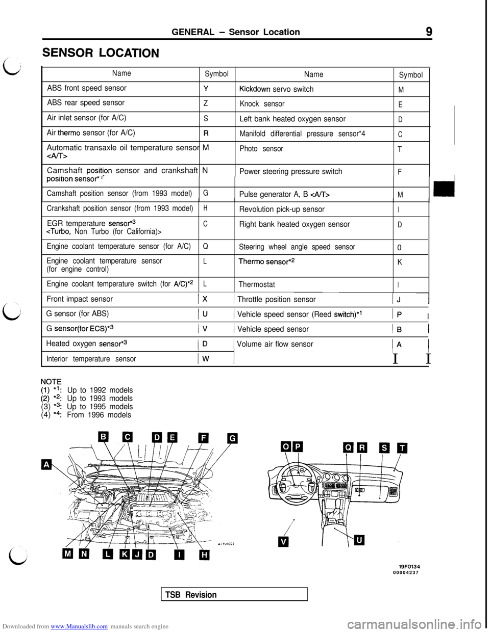
Downloaded from www.Manualslib.com manuals search engine GENERAL - Sensor Location9SENSOR
LOCATION
NameSymbol
Name
Symbol
ABS front speed sensorYKickdown servo switchM
ABS rear speed sensorZ
Knock sensorE
Air inlet sensor (for A/C)SLeft bank heated oxygen sensorD
Air therm0 sensor (for A/C)RManifold differential pressure sensor*4CAutomatic transaxle oil temperature sensor M
4lT>Photo sensor
TCamshaft
posit!on sensor and crankshaft N. . .Power steering pressure switchFposrtton sensor” I
Camshaft position sensor (from 1993 model)GPulse generator A, B M
Crankshaft position sensor (from 1993 model)HRevolution pick-up sensorI
EGR temperature sensor*3CcTurbo, Non Turbo (for California)>Right bank heated oxygen sensorD
Engine coolant temperature sensor (for A/C)QSteering wheel angle speed sensor0
Engine coolant temperature sensorL(for engine control)Therm0 sensor*2
K
Engine coolant temperature switch (for
A/C)*2LThermostatI
Front impact sensorIx1 Throttle position sensorIJ 1
G sensor (for ABS)PJ( Vehicle speed sensor (Reed switch)*’Ip I
G sensor(for ECS)*31 Vehicle speed sensorIB 1
Heated oxygen sensor*”ID( Volume air flow sensortA 1/III
Interior temperature sensorIw II I
NOIF
I:;
:
*2:
Up to 1992 models(3)
*3:
Up to 1993 models(4)
*a:
Up to 1995 models
From 1996 models
19FO13400004237
TSB Revision
Page 13 of 738
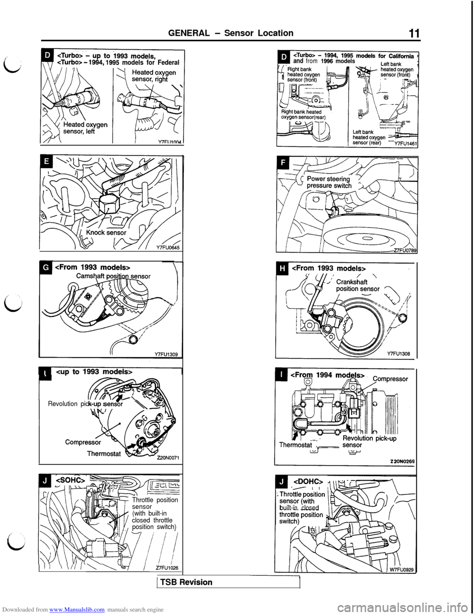
Downloaded from www.Manualslib.com manuals search engine GENERAL - Sensor Location
o> - 1994,1995 models for Federal
CUD to1993models>
r- m0.: \I0
wRevolution pick-up sens’or\u
/c, fdI
Throttle position
sensor
(with built-in
closed throttle
position switch)
and from1966 models
built-in closed
) ) 1\ \l/ / \ \v/~~1026
1 TSB Revision
Page 48 of 738
Downloaded from www.Manualslib.com manuals search engine 46CONFIGURATION DIAGRAMS - Engine and Transaxle
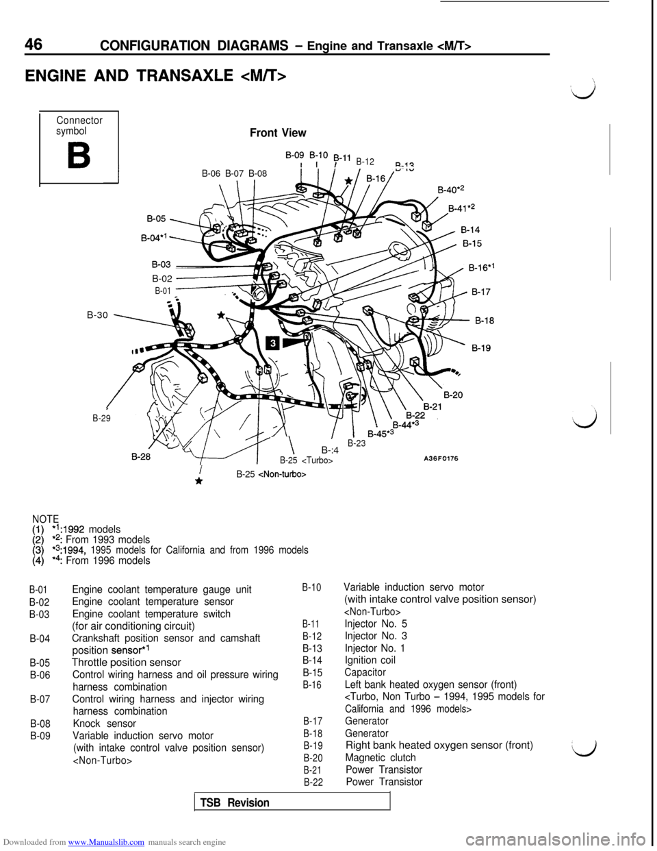
ENGINE AND TRANSAXLE
Connector
symbol
B
Front View
B-0: B;lO 53-11B-12R-i?
IB-06 B-07 B-08B-40*’
B-02
------+
B-01B-30
\ 7
I
B-29
- \B-:4B-23
B-25
A36F0176
B-01
B-02
B-03
B-04
B-05
B-06
B-07
B-08
B-09
i*B-25
NOTE
[:I*‘A992 models*2: From 1993 models*s:1994, 1995 models for California and from 1996 models*4: From 1996 models
Engine coolant temperature gauge unit
Engine coolant temperature sensor
Engine coolant temperature switch(for air conditioning circuit)
Crankshaft position sensor and camshaftposition
sensor*’Throttle position sensor
Control wiring harness and oil pressure wiring
harness combination
Control wiring harness and injector wiring
harness combination
Knock sensor
Variable induction servo motor
(with intake control valve position sensor)
B-10
B-11
B-12
B-13
B-14
B-15
B-16
B-17
B-18
B-19
B-20
B-21
B-22
Variable induction servo motor(with intake control valve position sensor)
Injector No. 5
Injector No. 3
Injector No. 1
Ignition coil
Capacitor
Left bank heated oxygen sensor (front)
California and 1996 models>
Generator
GeneratorRight bank heated oxygen sensor (front)
Magnetic clutch
Power Transistor
Power TransistorL)
TSB Revision
Page 50 of 738
Downloaded from www.Manualslib.com manuals search engine 48CONFIGURATION DIAGRAMS - Ennine and Transaxle
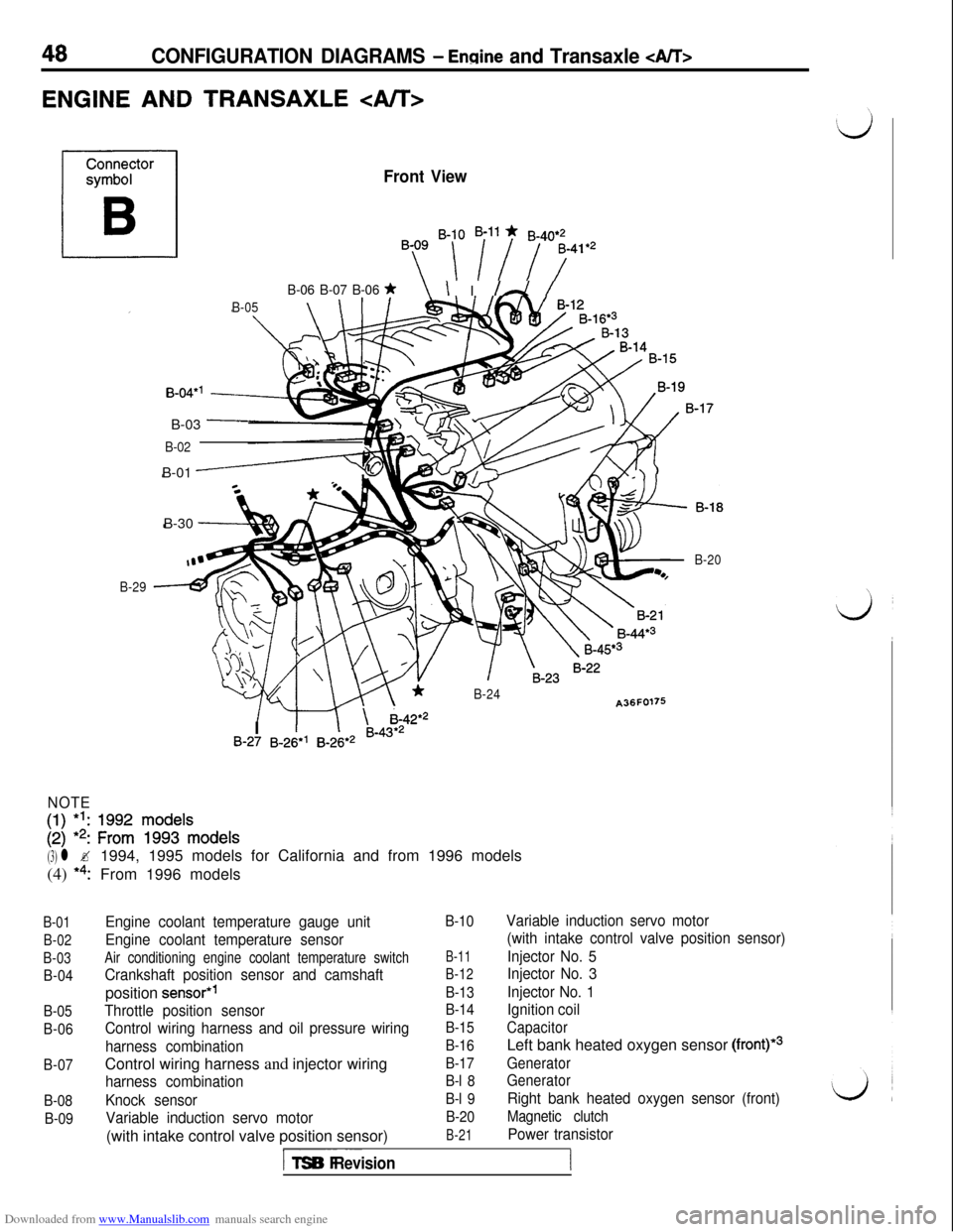
ENGINE AND TRANSAXLE
Front View
By ‘-[ i”i 7741e2
B-06 B-07 B-06 *\ I I /A /
B-05\ \IB-30
-
B-04*’B-03
-
B-02B-01
-
B-29
*B-24A36F0176
/ m \ i-42*2
B-20I
1IB-27 B-26*’ B-26*2 B-43*2
NOTE
[:I 1:: zif ~$$‘~ode~s
(3) l ?1994, 1995 models for California and from 1996 models
(4)
*4:From 1996 models
B-01
B-02
B-03
B-04
B-05
B-06
B-07
B-08
B-09
Engine coolant temperature gauge unit
Engine coolant temperature sensor
Air conditioning engine coolant temperature switch
Crankshaft position sensor and camshaftposition
sensor*’
Throttle position sensor
Control wiring harness and oil pressure wiring
harness combinationControl wiring harness and injector wiring
harness combination
Knock sensor
Variable induction servo motor(with intake control valve position sensor)
B-10
B-11
B-12
B-13
B-14
B-15
B-16
B-17
B-l 8
B-l 9
B-20
B-21
Variable induction servo motor
(with intake control valve position sensor)
Injector No. 5
Injector No. 3
Injector No. 1
Ignition coil
CapacitorLeft bank heated oxygen sensor
(front)*3
Generator
Generator
Right bank heated oxygen sensor (front)
Magnetic clutch
Power transistor
I-- ~~~TSB Revision
Page 166 of 738
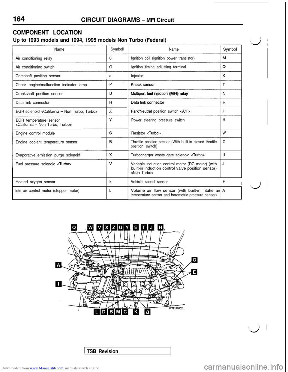
Downloaded from www.Manualslib.com manuals search engine CIRCUIT DIAGRAMS - MFI Circuit
COMPONENT LOCATIONUp to 1993 models and 1994, 1995 models Non Turbo (Federal)
NameSymbol
Air conditioning relay0
Air conditioning switch
Camshaft position sensor
a
Check engine/malfunction indicator lampP
Crankshaft position sensorD
Data link connectorR
EGR solenoid
EGR temperature sensor
Engine control module
Engine coolant temperature sensor
Evaporative emission purge solenoid
Fuel pressure solenoid
Heated oxygen sensorE
idle air control motor (stepper motor)L
Name/ Symbol
Ignition coil (ignition power transistor)
Ignition timing adjusting terminal
Injector
(1
Multrport fuel rnjectron (MFI) relay
ParWNeutral position switch c&T>
Power steering pressure switchH
Resistor
Throttle position sensor (With built-in closed throttleCposition switch)
Turbocharger waste gate solenoid
Variable induction control motor (DC motor) (withJbuilt-in induction control valve position sensor)
Vehicle speed sensorFIVolume air flow sensor (with built-in intake air A
temperature sensor and barometric pressure sensor)
1 TSB Revision
Page 167 of 738
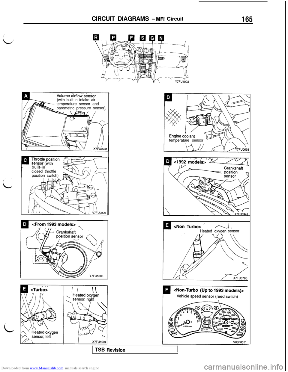
Downloaded from www.Manualslib.com manuals search engine CIRCUIT DIAGRAMS - MFI Circuit165
-x- --q-Y7FU1003
Volume &flo~‘.&&sor(with built-in intake air
temperature sensor and
barometric pressure sensor)
temperature sensor
Pbuilt-in
I
closed throttle
position switch)
TSB Revision
Page 369 of 738
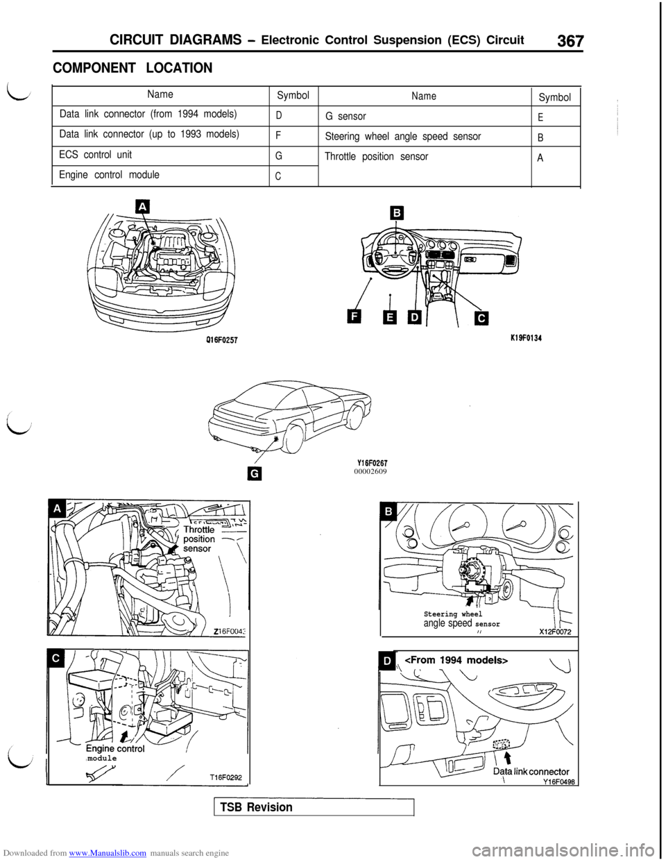
Downloaded from www.Manualslib.com manuals search engine CIRCUIT DIAGRAMS - Electronic Control Suspension (ECS) Circuit367
COMPONENT LOCATION
Name
Data link connector (from 1994 models)
Data link connector (up to 1993 models)
ECS control unit
Engine control moduleSymbolNameSymbol
DG sensorE
FSteering wheel angle speed sensorB
G
Throttle position sensor
A
C
016FO257
module
/T16F0292
Y16FO26700002609
K19F0134
- IISteering wheelangle speed sensorI,X12FOO72
\
\Y16FO496
TSB Revision
Page 375 of 738
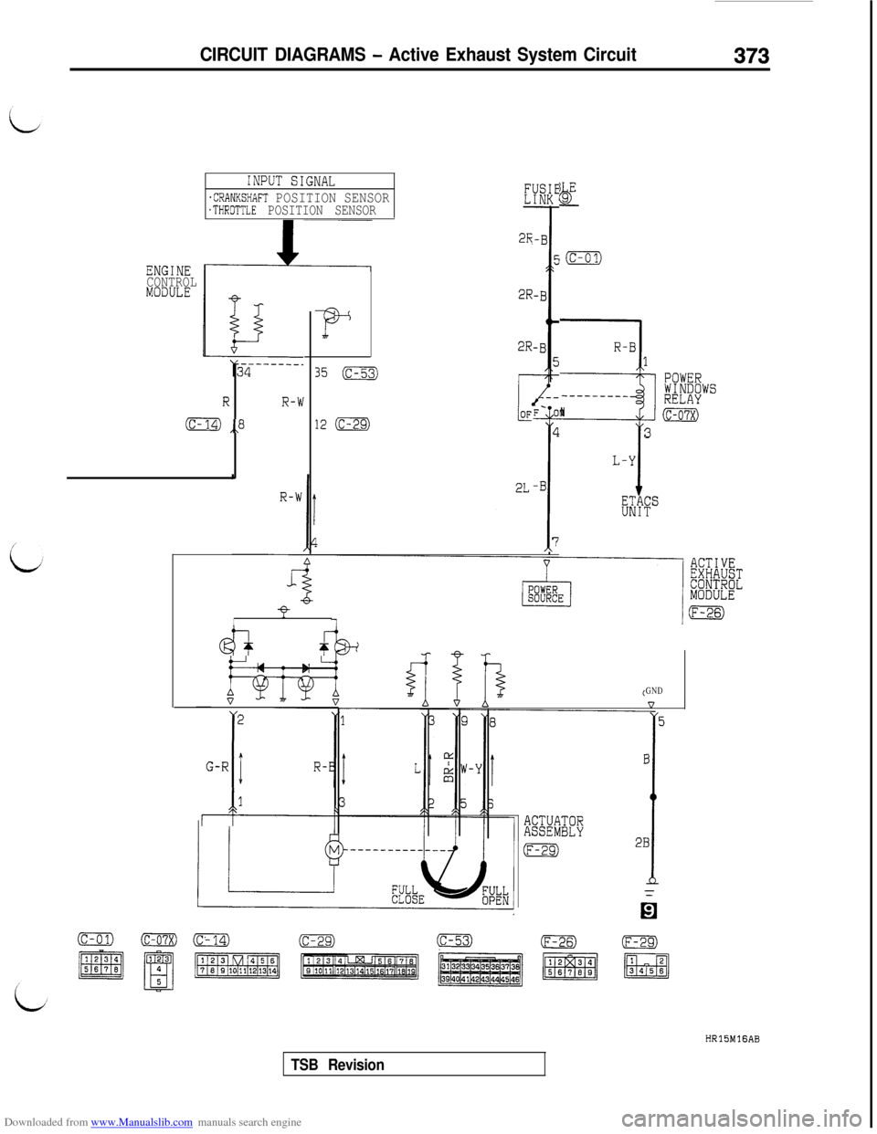
Downloaded from www.Manualslib.com manuals search engine CIRCUIT DIAGRAMS - Active Exhaust System Circuit373
ENGINE
CONTROL
MODULE
INPUT SIGNAL
.CRANKSHAFT POSITION SENSOR.THROTTLE POSITION SENSOR
RR-W
(c- ,,8
F
35 (c-53)
12 (c-29)
2R
2R
2R
I
@I-+ f
2
G-R
IIR-B
r-k-
F- 01
4
T
-B
7
bjgE-
‘(c-01)
R-B1
3
POWERWINDOWS-____---_RELAYN(c-07x)
3
L-Y
KkF"
GND
5
ACTUATORASSEMBLY
lEgI
B
i
2B
(c-01)o(c’14)m(c-53)(F-26)HRlSMlGAB
TSB Revision
Page 381 of 738
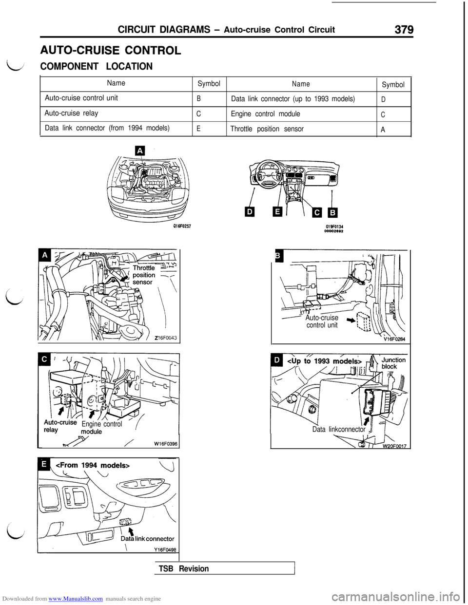
Downloaded from www.Manualslib.com manuals search engine CIRCUIT DIAGRAMS - Auto-cruise Control Circuit379AUTO-CRUISE
CONTROL
COMPONENT LOCATION
Name
Auto-cruise control unit
Auto-cruise relay
Data link connector (from 1994 models)Symbol
NameSymbol
BData link connector (up to 1993 models)D
CEngine control moduleC
E
Throttle position sensor
APlGFO257
o-cruiseEngine control
%Y /W16FO396
wow.ee2
m?zYili .[L Auto-cruisecontrol unit1ul’-~,;>
\ \\\ 1I!,- ii i-*uwl
Data linkconnector J
-0017
TSB Revision
Page 731 of 738
Downloaded from www.Manualslib.com manuals search engine ALPHABETICAL INDEX1
A
iiABSPOWER RELAY, Check . . . . . . . . . . . . . . . . . . . . , . . .
35-82-lRELAY.............................................35-110-1SIGNAL, On-vehicle Inspection.................13A-176,277-iACCELERATOR
CABLE..............................................
17-4-l
SWITCH
ACTIVE AERO SYSTEM, Check.........................
51-7-l
ACTIVE EXHAUST
CONTROL UNIT, On-vehicle Inspection..........13A-173,274-lSYSTEM............................................15-40-l
AERO PARTS........................................51-19-lAIR BAG..........................................520-74-lMODULE......................................528-82, 87-lAIR CLEANER.........................................15-9-l
ELEMENT, Maintenance..............................00-45-lAIR CONDITIONING...................................55-3-l
55-18-lCONTROL PANEL...................................55-73-lCONTROL UNIT.....................................55-73-lENGINE COOLANT TEMPERATURE SWITCHEngine Cooling.....................................14-13-l
ASSIST LINK
Maintenance
.........................................00-49-IAXLE
Rear
HUB, Rear -&VD>
....................................
27-4-lSHAFT
B
BALL JOINT SEALS, Maintenance. . . .
BAROMETRIC PRESSURE SENSOR
On-vehicle Inspection . . . . . . . . . . . .BASIC IDLE SPEED, Adjustment . . . . . .
BATTERY . . . . . . . . . . . . . . . . . . . . . . . . . .
Discharged, Remedy . . . . . . . . . . . .
BELT LOCK CONTROLLER . . . . . . . . .
BLOWER. . . . . . . . . . . . . . . . . .
BOOSTER, Clutch
Parking. . . . . . . . . . ..*.............
BOOSTER . . . . . . . . . . . . . . . .
Operating Check . . . . . . . . . . . . . . . .
. . . . . . . . . . . . . . . .00-52-l
..........13A-91,217-l..............
13A-55-l................64-3-11................35-82-l............55-32,74-t................
55-35-l.................21-6-l.........13A-171,273-l
.................36-8-l................35-87-l................35-64-l
DISC..........................................35-93,103-l
Front, Check.......................................35-70-IRear, Check........................................35-73-lFLUID LEVEL SENSOR, Check........................35-64-l
HOSES, Maintenance.................................00-52-I
LINE................................................35-91-lLINING.............................................35-74-lPAD
Disc, Front.........................................
35-66-l
Disc, Rear.............~..................>..........35-71-lPEDAL.............................................35-84-l
Check and Adjustment......................
:........35-63-lBUMPERFront...............................................51-8-lRear...............................................51-13-l
CAMSHAFT
OIL SEALS..........................................
11-21-lPOSITION SENSOR, On-vehicle Inspection......13A-103,225-lCATALYTIC CONVERTER..............................17-71-l
..........................................
15-33-lCD AUTO CHANGER................................54-191-11CENTER PILLAR GLASS..............................42-33-l
CENTRAL DOOR LOCKING SYSTEM...................42-49-lCHARGE AIR COOLER................................15-11-l
CHARGING SYSTEM..................................l.6-2-11CIGARETTE LIGHTER..............................54-123-k
CLOCK SPRING, SRS..............................528-74-I
CLOSED THROTTLE POSITION SWITCH
Adjustment.......................................
13A-57-lOn-vehicle Inspection.........................13A-101,223-lCLUTCH
BOOSTER OPERATING, Check
MASTER CYLINDER.................................21-14-lPEDAL..............................................21-8-lCheck and Adjustment................................21-5-l
RELEASE CYLINDER................................21-16-IVACUUM LINE cAWD>...............................21-18-I
COLUMN SWITCH..................................54-112-11COMBINATION GAUGES.............................54-33-kCOMBINATION LIGHT...............................54-106-11COMBINATION METERS.............................54-31-11COMPRESSOR CLUTCH RELAY,On-vehicle Inspection...........................13A-123,236-lCONDENSER
Active Exhaust, On-vehicle Inspection...........13A-173,274-lECS.............................................338-20-I
Electronic CABS>..................................35-119-l
CONTROL VALVE.....................................37B-9-l
Fuel Tank Pressure..................................13F-6-IInspection..
........................................17-65-l
CRANKSHAFT
FRONT OIL SEAL....................................
11-25-lPOSITION SENSOR, On-vehicle Inspection......13A-107,227-l
REAR QIL SEAL.....................................11-26-l