turn signal MITSUBISHI 380 2005 Workshop Manual
[x] Cancel search | Manufacturer: MITSUBISHI, Model Year: 2005, Model line: 380, Model: MITSUBISHI 380 2005Pages: 1500, PDF Size: 47.87 MB
Page 850 of 1500
ON-VEHICLE SERVICE
HEATER, AIR CONDITIONING AND VENTILATION55-149
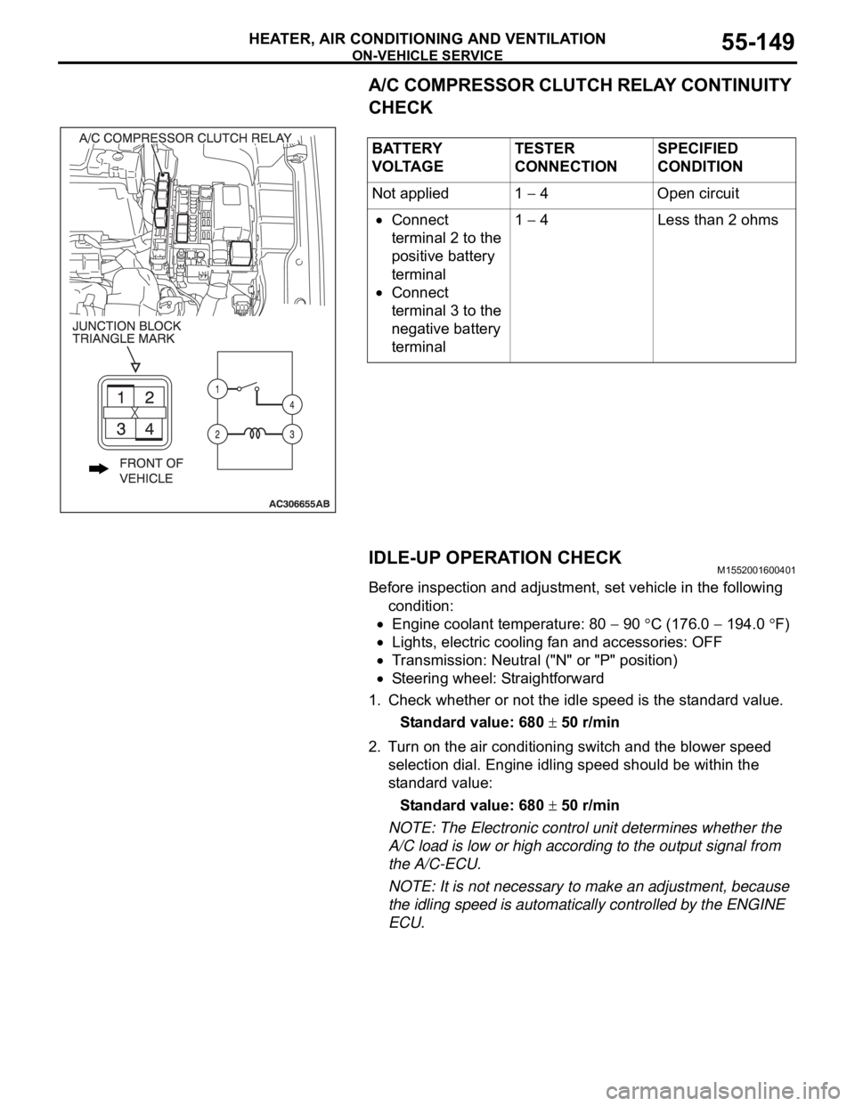
A/C COMPRESSOR CLUTCH RELAY CONTINUITY
CHECK
IDLE-UP OPERATION CHECK
M1552001600401
Before inspection and adjustment, set vehicle in the following
condition:
Engine coolant temperature: 80 90 C (176.0 194.0 F)
Lights, electric cooling fan and accessories: OFF
Transmission: Neutral ("N" or "P" position)
Steering wheel: Straightforward
1. Check whether or not the idle speed is the standard value.
Standard value: 680
50 r/min
2. Turn on the air conditioning switch and the blower speed
selection dial. Engine idling speed should be within the
standard value:
Standard value: 680
50 r/min
NOTE: The Electronic control unit determines whether the
A/C load is low or high according to the output signal from
the A/C-ECU.
NOTE: It is not necessary to make an adjustment, because
the idling speed is automatically controlled by the ENGINE
ECU. BATTERY
V O LTA G ETESTER
CONNECTIONSPECIFIED
CONDITION
Not applied 1
4 Open circuit
Connect
terminal 2 to the
positive battery
terminal
Connect
terminal 3 to the
negative battery
terminal1
4 Less than 2 ohms
Page 935 of 1500
ENGINE COOLING DIAGNOSIS
ENGINE COOLING14-20
STEP 23. MUT-III self-diag code
Check if an MPI system self-diag code is set. (Refer to GROUP
13A - Trouble shooting 13A-5).
Q: Diagnosis code set?
YES : Inspection chart for diagnosis code (Refer to GROUP
13A - Trouble shooting 13A-17)
NO : Replace the engine-ECU (Refer to GROUP 13A,
Engine-ECU 13A-675 ). Then go to Step 24.
STEP 24. Check the symptoms.
Q: Does the radiator fan motor and the condenser fan
motor operate correctly?
YES : This symptom is complete.
NO : Return to Step 1.
INSPECTION PROCEDURE 4: Radiator Fan and Condenser Fan do not Change Speed or Stop
.
Radiator Fan and Condenser Fan Drive
Circuit
Refer to 5.
.
TECHNICAL DESCRIPTION
The cause could be a malfunction of the fan con-
troller power supply or earth circuit.
If the communication line wiring harness between
the fan controller and the engine-ECU is
short-circuited to earth, the radiator fan motor
and the condenser fan motor will not rotate.
The cause could also be a malfunction of input
signal from the A/C switch, the water temperature
sensor unit and the vehicle speed sensor
or the output shaft speed sensor to the
engine-ECU.
The cause could also be a malfunction of the fan
controller or the engine-ECU.
.
TROUBLESHOOTING HINTS
Malfunction of fusible link No.2
Malfunction of fan control relay
Malfunction of cooling fan motor
Malfunction of fan controller
Malfunction of engine-ECU
Damaged wiring harness or connector
DIAGNOSIS
STEP 1. Check the fan control relay.
Refer to 14-31.
Q: Is the fan control relay in good condition?
YES : Go to Step 2.
NO : Replace the fan control relay. Then go to Step 8.
Page 1007 of 1500
IGNITION SYSTEM
ENGINE ELECTRICAL16-30
IGNITION SYSTEM
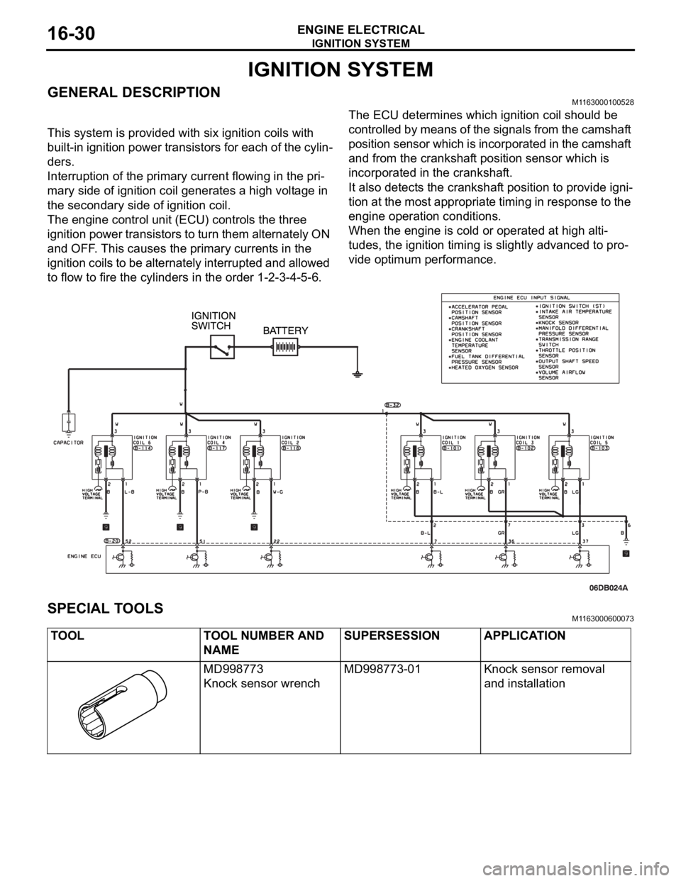
GENERAL DESCRIPTIONM1163000100528
This system is provided with six ignition coils with
built-in ignition power transistors for each of the cylin-
ders.
Interruption of the primary current flowing in the pri-
mary side of ignition coil generates a high voltage in
the secondary side of ignition coil.
The engine control unit (ECU) controls the three
ignition power transistors to turn them alternately ON
and OFF. This causes the primary currents in the
ignition coils to be alternately interrupted and allowed
to flow to fire the cylinders in the order 1-2-3-4-5-6.The ECU determines which ignition coil should be
controlled by means of the signals from the camshaft
position sensor which is incorporated in the camshaft
and from the crankshaft position sensor which is
incorporated in the crankshaft.
It also detects the crankshaft position to provide igni-
tion at the most appropriate timing in response to the
engine operation conditions.
When the engine is cold or operated at high alti-
tudes, the ignition timing is slightly advanced to pro-
vide optimum performance.
SPECIAL TOOLSM1163000600073
TOOL TOOL NUMBER AND
NAMESUPERSESSION APPLICATION
MD998773
Knock sensor wrenchMD998773-01 Knock sensor removal
and installation
Page 1047 of 1500

WINDSHIELD WIPER AND WASHER
EXTERIOR51-14
WINDSHIELD WIPER AND WASHER
GENERAL DESCRIPTIONM1511000100558
WINDSHIELD WIPER AND WASHER
OPERATION
.
WINDSHIELD LOW-SPEED (AND
HIGH-SPEED) WIPER OPERATION
If the windshield low-speed wiper switch is turned
to the ON position with the ignition switch at the
"ACC" or "ON" position, the column switch sends
a low-speed wiper ON and high-speed wiper OFF
signals to the front-ECU. This turns the wiper sig-
nal on and the wiper speed control relay off
(low-speed), causing the wipers to operate at
low-speed.
If the windshield high-speed wiper switch is
turned to the ON position, the column switch
sends a low-speed wiper OFF and high-speed
wiper ON signals to the front-ECU. This turns
both the wiper signal and the wiper speed control
relay on (high-speed), causing the wipers to
operate at high-speed.
NOTE: The windshield wiper speed is adjustable
with the built-in wiper speed control relay.
High-speed operations take place when the wiper
speed control relay is set to "ON" and low-speed
operations take place when the wiper speed control
relay is set to "OFF".
.
WINDSHIELD INTERMITTENT WIPER
OPERATION
The ETACS-ECU calculates the wiper operation
interval according to the voltage signal sent from the
column switch. Then the ETACS-ECU sends a signal
to the front-ECU. The front-ECU determines the
wiper operation interval and turns on the wiper relay
signal relay. This causes the wiper auto stop relay to
turn on. Then the wiper auto stop relay will turn off
after the wipers reach the park position. This causes
the wiper signal relay and then the wipers to turn off.
If the wiper signal relay remains off for the wiper
operation interval, the relay turns on again, causing
the wipers to operate in intermittent mode.
.
WINDSHIELD MIST WIPER OPERATION
If the windshield mist wiper switch is turned to the
ON position with the ignition switch at the "ACC"
or "ON" position, the mist wiper high-speed oper-
ation signal is sent to the front-ECU. This signal
turns on the wiper speed control relay, causing
the wipers to work at high-speed while the mist
switch is on.
While the windshield mist wiper switch remains
turned on when the intermittent mode is still work-
ing, the wipers work as the mist wiper. However,
the wipers return to the intermittent mode again
when the switch is changed back to "INT" posi-
tion.
To prevent the windshield mist wiper from operat-
ing when the windshield wiper switch is turned
OFF, the windshield mist wiper does not work for
0.5 second after the windshield intermittent wiper
switch, the windshield low-speed wiper switch
and the windshield high-speed wiper switch are
turned OFF.
.
WINDSHIELD WASHER OPERATION
If the windshield washer switch is turned to the
ON position with the ignition switch at "ACC" or
"ON" position, the windshield washer ON signal is
sent to the front-ECU. After 0.3 second, the wind-
shield wiper signal turns on. After the windshield
washer switch signal turns off, the windshield
wiper signal turns off in three seconds.
If the windshield washer switch is turned on while
the windshield wiper is at intermittent mode, and
the windshield washer switch is turned OFF
within 0.2 second, the wiper works only once to
perform mist operation. When the windshield
washer switch is turned on for more than 0.2 sec-
ond, the wiper performs the same movement as
normal condition from the time when 0.2 second
has elapsed, and then returns to intermittent
operation.
WINDSHIELD WIPER AND WASHER DIAGNOSISM1511000700389
The windshield wiper and washer are controlled by
the Simplified Wiring System (SWS). For trouble-
shooting, refer to GROUP 54B, SWS Diagnosis
P.54B-10.NOTE: Even when the ETACS-ECU has failed, the
windshield wiper can work at low speed as fail-safe
mode. (Normally, the windshield wiper operates
when the ignition switch is at the "ACC" position. But,
if it enters the fail-safe mode, the wiper can operate
only when the ignition switch is at the "ON" position.)
Page 1134 of 1500

KEYLESS ENTRY SYSTEM
BODY42-67
KEYLESS ENTRY SYSTEM
GENERAL DESCRIPTIONBGBJABIE
Antenna and receiver are incorporated in the
ETACS-ECU.
ID code can be registered by using Diagnostic
tool (MUT-III).
Transmitter is a key holder type, which incorpo-
rates lock button, unlock button, trunk button and
panic button
When the transmitter unlock button is pressed
once, the driver's door will be unlocked. If the but-
ton is pressed twice, all the doors will be
unlocked. The adjustment function also allows
you to open all the doors by pressing the unlock
button only once. For further details on using the
multi-center display to adjust the unlock opera-
tion, refer to GROUP 54B, On-vehicle Service
P.54B-486.
When the transmitter is operated, the answer-
back function will work as follows:
The answerback operation can be altered as fol-
lows:NOTE: Enabling/disabling the hazard warning
light flashing, the horn sounding in accordance
with the answerback function. For further details
on using the transmitter to adjust answerback,
P.42-72 see the section below. For further details
on using the multi-center display to adjust
answerback, refer to GROUP 54B, On-vehicle
Service P.54B-486. ITEM OPERATION
DOORS LOCKED DOORS UNLOCKED
Dome light Flashes once Illuminates for 15 seconds
Turn-signal lights (RH and LH) Flashes once Flashes twice
Horn Sounds once when the lock button
is pressed with all the doors locked-
ITEM ADJUSTMENT ITEM ADJUSTMENT DETAIL
Keyless entry system
confirmation by turn
signal lightsAdjustment of hazard answerback
when the transmitter is used to
lock doorsWhen adjusting hazard answerback after the
doors are locked with the transmitter, the
following flashing conditions can be selected.
a. Flash (default)
b. No flash
Adjustment of hazard answerback
when the transmitter is used to
unlock doorsWhen adjusting hazard answerback after the
doors are unlocked with the transmitter, the
following flashing conditions can be selected.
a. Flash (default)
b. No flash
Keyless entry system
confirmation by hornAdjustment of horn answerback
when the transmitter is used to
lock doorsWhen adjusting horn answerback after the
doors are locked with the transmitter, the
following horn conditions can be selected.
a. Horn sounds
b. Horn sounds if doors are already locked
(default)
c. Horn does not sound
Page 1138 of 1500

KEYLESS ENTRY SYSTEM
BODY42-71
KEYLESS ENTRY SYSTEM INSPECTIONBGBHCDAE
Check the following items. If defective, refer to GROUP 54B,
SWS Diagnosis P.54B-10).
1. Operate the transmitter to check that the doors can be
locked and unlocked.
NOTE: The adjustment function allows you to change the
unlock operation setting as follows. Prior to that check, con-
firm which setting is activated.
.
a. When the unlock button is pressed once, the driver's
door will be unlocked. Then when the button is pressed
once again, all the doors will be opened (initial setting).
b. When the unlock button is pressed only once, all the
doors will be opened.
2. Press the trunk lid button of transmitter twice (press once,
and then press again within 5 seconds) and confirm that the
trunk lid opens.
3. Operate the transmitter to check that the answerback
function works in response to doors locking/unlocking.
NOTE: The adjustment function allows you to change the
hazard answerback setting as follows. Prior to that check,
confirm which setting is activated.
.
a. Turn-signal lights: Flash once when doors are locked,
and twice when unlocked (initial setting)
b. Turn-signal lights: Flash once when doors are locked,
but does not flash when unlocked.
c. Turn-signal lights: Do not flash when doors are locked,
but flash twice when unlocked.
d. Turn-signal lights: Do not flash when doors are locked
and unlocked.
NOTE: The adjustment function allows you to change the
horn answerback setting as follows. Prior to that check, con-
firm which setting is activated.
.
a. Horn: Sounds once when the lock button is pressed.
b. Horn: Sounds once when the lock button is pressed (ini-
tial setting).
c. Horn: Does not sound.
KEYLESS ENTRY SYSTEM TIMER LOCK
FUNCTION INSPECTION
BGBEBDIA
If the doors are not locked within 30 seconds after the unlock
button is pressed, refer to GROUP 54B, SWS Diagnosis
P.54B-10.
NOTE: If either of the doors is opened or the key is inserted in
the ignition switch within that 30-second period, the timer lock
function will be cancelled.
Page 1139 of 1500

KEYLESS ENTRY SYSTEM
BODY42-72
NOTE: The adjustment function allows you to change the timer
lock period from 30 seconds (initial setting) to 60, 120 or 180
seconds. Prior to this inspection, confirm which setting is acti-
vated.
ENABLING/DISABLING THE ANSWERBACK
FUNCTION
BGBDGCGD
When the doors are locked or unlocked by using the transmit-
ter, the dome light will flash/illuminate, the turn-signal lights will
flash (hazard answerback), or the horn will sound (horn
answerback) to inform the driver.
The hazard answerback and horn answerback functions can be
enabled or disabled according to the following procedure:
ENABLING/DISABLING THE HAZARD
ANSWERBACK FUNCTION
.
How to adjust hazard answerback when the trans-
mitter is used to lock doors
1. Remove the ignition key.
2. Push the ”unlock” button and then push the ”lock“ button
within 4 seconds to 10 seconds.
3. Release the ”lock” button within 10 seconds after Step 2 and
then release the “unlock” button. The ETACS-ECU tone
alarm will sound, indicating that the hazard answerback
function can be enabled or disabled when the doors are
locked.
Enable the hazard answerback function when the
doors are locked: The ETACS-ECU tone alarm will
sound once.
Disable the hazard answerback function when the
doors are locked: The ETACS-ECU tone alarm will
sound twice.
.
How to adjust hazard answerback when the
transmitter is used to unlock doors
1. Remove the ignition key.
2. Push the ”unlock” button and then push the ”lock“ button
within 4 seconds to 10 seconds.
3. Release the ”lock” button within 10 seconds after Step 2 and
then release the “unlock” button. The ETACS-ECU tone
alarm will sound, indicating that the hazard answerback
function can be enabled or disabled when the door are
unlocked.
Enable the hazard answerback function when the
doors are unlocked: The ETACS-ECU tone alarm
will sound once.
Disable the hazard answerback function when the
doors are unlocked: The ETACS-ECU tone alarm
will sound twice.
Page 1287 of 1500
TRACTION CONTROL SYSTEM (TCL) DIAGNOSIS
TRACTION CONTROL SYSTEM (TCL)13C-8
DIAGNOSTIC TROUBLE CODE CHARTM1136003300022
During diagnosis, a DTC associated with other
system may be set when the ignition switch is
turned on with connector(s) disconnected. On
completion, confirm all systems for DTC(s). If
DTC(s) are set, erase them all.
NOTE: If the ABS-8 ECU or the active wheel
speed sensor are disconnected, or if the wiring is
an open/ short circuit, the ABS 8 ECU will shut
off power supply to the respective wheel speed
sensor. All other wheel speed sensors will oper-
ate normally. To restore the power supply, the
ignition switch must be turned to the "OFF" posi-
tion then to the "ON" position again.Follow the inspection chart that is appropriate for the
diagnostic trouble code.
DTC INSPECTION ITEM DIAGNOSTIC CONTENT REFERENCE PAGE
C1200 Front right wheel speed sensor Open circuit or short circuit GROUP 35B, ABS
Diagnosis
Diagnostic Trouble
Code Procedures
C1200 P.35B-10
C1201 Front right wheel speed sensor Abnormal output signal GROUP 35B, ABS
Diagnosis
Diagnostic Trouble
Code Procedures
C1201 P.35B-26
C1205 Front left wheel speed sensor Open circuit or short circuitGROUP 35B, ABS
Diagnosis
Diagnostic Trouble
Code Procedures
C1205 P.35B-10
C1206 Front left wheel speed sensor Abnormal output signal GROUP 35B, ABS
Diagnosis
Diagnostic Trouble
Code Procedures
C1206 P.35B-26
C1210 Rear right wheel speed sensor Open circuit or short circuitGROUP 35B, ABS
Diagnosis
Diagnostic Trouble
Code Procedures
C1210 P.35B-10
C1211 Rear right wheel speed sensor Abnormal output signal GROUP 35B, ABS
Diagnosis
Diagnostic Trouble
Code Procedures
C1211 P.35B-26
C1215 Rear left wheel speed sensor Open circuit or short circuit GROUP 35B, ABS
Diagnosis
Diagnostic Trouble
Code Procedures
C1215 P.35B-10
Page 1289 of 1500
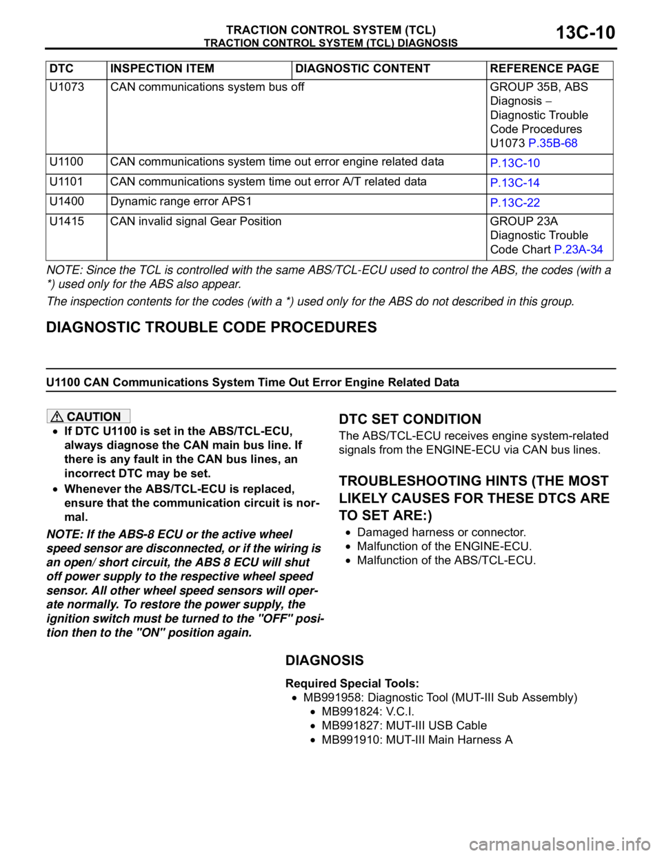
TRACTION CONTROL SYSTEM (TCL) DIAGNOSIS
TRACTION CONTROL SYSTEM (TCL)13C-10
NOTE: Since the TCL is controlled with the same ABS/TCL-ECU used to control the ABS, the codes (with a
*) used only for the ABS also appear.
The inspection contents for the codes (with a *) used only for the ABS do not described in this group.
DIAGNOSTIC TROUBLE CODE PROCEDURES
U1100 CAN Communications System Time Out Error Engine Related Data
If DTC U1100 is set in the ABS/TCL-ECU,
always diagnose the CAN main bus line. If
there is any fault in the CAN bus lines, an
incorrect DTC may be set.
Whenever the ABS/TCL-ECU is replaced,
ensure that the communication circuit is nor-
mal.
NOTE: If the ABS-8 ECU or the active wheel
speed sensor are disconnected, or if the wiring is
an open/ short circuit, the ABS 8 ECU will shut
off power supply to the respective wheel speed
sensor. All other wheel speed sensors will oper-
ate normally. To restore the power supply, the
ignition switch must be turned to the "OFF" posi-
tion then to the "ON" position again.
.
DTC SET CONDITION
The ABS/TCL-ECU receives engine system-related
signals from the ENGINE-ECU via CAN bus lines.
.
TROUBLESHOOTING HINTS (THE MOST
LIKELY CAUSES FOR THESE DTCS ARE
TO SET ARE:)
Damaged harness or connector.
Malfunction of the ENGINE-ECU.
Malfunction of the ABS/TCL-ECU.
DIAGNOSIS
Required Special Tools:
MB991958: Diagnostic Tool (MUT-III Sub Assembly)
MB991824: V.C.I.
MB991827: MUT-III USB Cable
MB991910: MUT-III Main Harness A U1073 CAN communications system bus off GROUP 35B, ABS
Diagnosis
Diagnostic Trouble
Code Procedures
U1073 P.35B-68
U1100 CAN communications system time out error engine related data
P.13C-10
U1101 CAN communications system time out error A/T related data
P.13C-14
U1400 Dynamic range error APS1
P.13C-22
U1415 CAN invalid signal Gear Position GROUP 23A
Diagnostic Trouble
Code Chart P.23A-34 DTC INSPECTION ITEM DIAGNOSTIC CONTENT REFERENCE PAGE
Page 1297 of 1500

TRACTION CONTROL SYSTEM (TCL) DIAGNOSIS
TRACTION CONTROL SYSTEM (TCL)13C-18
STEP 6. Using diagnostic tool MB991958, read the
diagnostic trouble code.
To prevent damage to diagnostic tool MB991958, always
turn the ignition switch to the "LOCK" (OFF) position
before connecting or disconnecting diagnostic tool
MB991958.
(1) Connect diagnostic tool MB991958 to the data link
connector. (Refer to P.13C-3).
(2) Turn the ignition switch to the "ON" position.
(3) Use diagnostic tool MB991958 to read the TCL diagnostic
trouble codes. (Refer to P.13C-3).
(4) Turn the ignition switch to the "LOCK" (OFF) position.
(5) Disconnect diagnostic tool MB991958.
Q: Is DTC U1101 set?
YES : Return to Step 1.
NO : The procedure is complete.
U1120 CAN Communications System TCL Uncontrollable by Engine Malfunction
If DTC U1120 is set in the ABS/TCL-ECU,
always diagnose the CAN main bus line. If
there is any fault in the CAN bus lines, an
incorrect DTC may be set.
Whenever the ABS/TCL-ECU is replaced,
ensure that the communication circuit is nor-
mal.
The engine control system-related DTC may
be set when DTC U1120 is set. (For details
refer to GROUP 00, Intersystem Affiliated DTC
Reference Table P.00-17). Diagnose the
engine control system first when the engine
control system-related DTC is set.
NOTE: If the ABS-8 ECU or the active wheel
speed sensor are disconnected, or if the wiring is
an open/ short circuit, the ABS 8 ECU will shut
off power supply to the respective wheel speed
sensor. All other wheel speed sensors will oper-
ate normally. To restore the power supply, the
ignition switch must be turned to the "OFF" posi-
tion then to the "ON" position again.
.
DTC SET CONDITION
The ABS/TCL-ECU receives engine system-related
signals from the Engine-ECU via CAN bus lines. If a
fail-safe related data is contained in the signal from
the Engine-ECU, DTC U1120 will be stored.
.
TROUBLESHOOTING HINTS (THE MOST
LIKELY CAUSES FOR THESE DTCS ARE
TO SET ARE:)
Damaged harness or connector.
Malfunction of the Engine-ECU.
Malfunction of the ABS/TCL-ECU.