Brake pad MITSUBISHI 380 2005 User Guide
[x] Cancel search | Manufacturer: MITSUBISHI, Model Year: 2005, Model line: 380, Model: MITSUBISHI 380 2005Pages: 1500, PDF Size: 47.87 MB
Page 1184 of 1500
ON-VEHICLE SERVICE
BASIC BRAKE SYSTEM35A-19
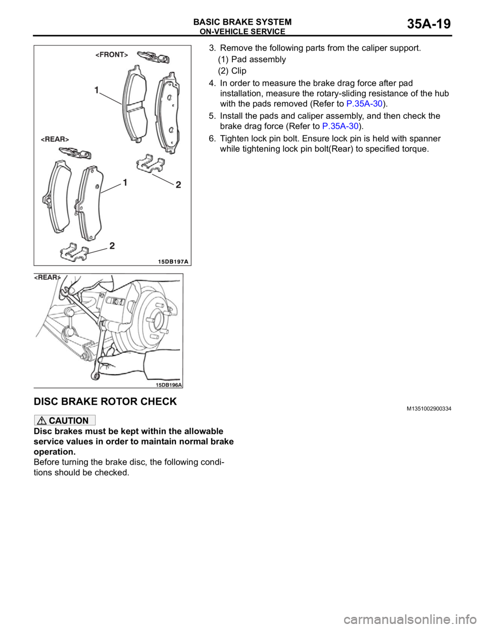
3. Remove the following parts from the caliper support.
(1) Pad assembly
(2) Clip
4. In order to measure the brake drag force after pad
installation, measure the rotary-sliding resistance of the hub
with the pads removed (Refer to P.35A-30).
5. Install the pads and caliper assembly, and then check the
brake drag force (Refer to P.35A-30).
6. Tighten lock pin bolt. Ensure lock pin is held with spanner
while tightening lock pin bolt(Rear) to specified torque.
DISC BRAKE ROTOR CHECKM1351002900334
Disc brakes must be kept within the allowable
service values in order to maintain normal brake
operation.
Before turning the brake disc, the following condi-
tions should be checked.
Page 1185 of 1500
ON-VEHICLE SERVICE
BASIC BRAKE SYSTEM35A-20
.
BRAKE DISC THICKNESS CHECK
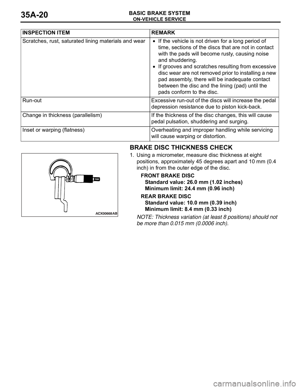
1. Using a micrometer, measure disc thickness at eight
positions, approximately 45 degrees apart and 10 mm (0.4
inch) in from the outer edge of the disc.
FRONT BRAKE DISC
Standard value: 26.0 mm (1.02 inches)
Minimum limit: 24.4 mm (0.96 inch)
REAR BRAKE DISC
Standard value: 10.0 mm (0.39 inch)
Minimum limit: 8.4 mm (0.33 inch)
NOTE: Thickness variation (at least 8 positions) should not
be more than 0.015 mm (0.0006 inch). INSPECTION ITEM REMARK
Scratches, rust, saturated lining materials and wear
If the vehicle is not driven for a long period of
time, sections of the discs that are not in contact
with the pads will become rusty, causing noise
and shuddering.
If grooves and scratches resulting from excessive
disc wear are not removed prior to installing a new
pad assembly, there will be inadequate contact
between the disc and the lining (pad) until the
pads conform to the disc.
Run-out Excessive run-out of the discs will increase the pedal
depression resistance due to piston kick-back.
Change in thickness (parallelism) If the thickness of the disc changes, this will cause
pedal pulsation, shuddering and surging.
Inset or warping (flatness) Overheating and improper handling while servicing
will cause warping or distortion.
Page 1189 of 1500
BRAKE PEDAL
BASIC BRAKE SYSTEM35A-24
BRAKE PEDAL
REMOVAL AND INSTALLATIONM1351003400406
Post-installation Operation
Brake Pedal Adjustment (Refer to P.35A-13).
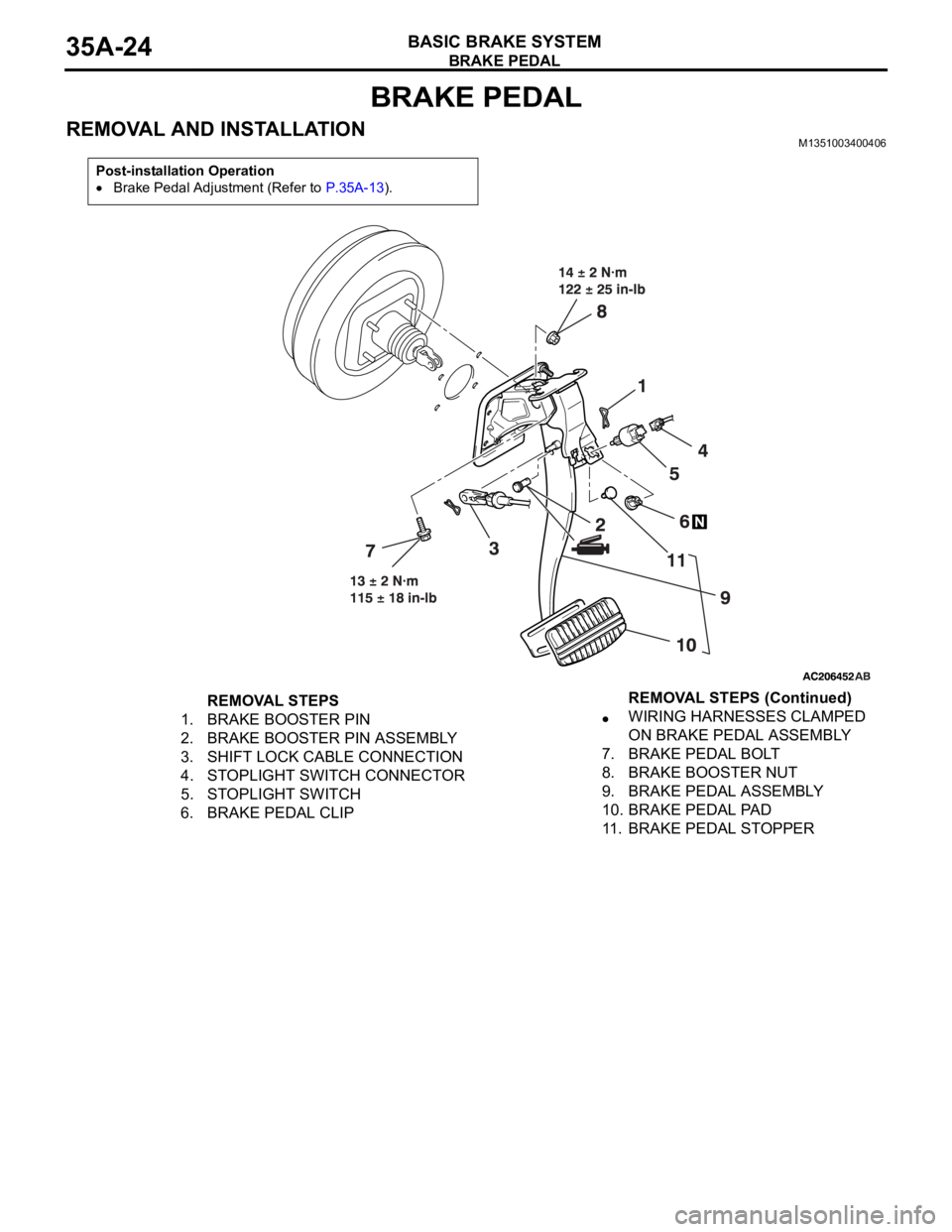
REMOVAL STEPS
1. BRAKE BOOSTER PIN
2. BRAKE BOOSTER PIN ASSEMBLY
3. SHIFT LOCK CABLE CONNECTION
4. STOPLIGHT SWITCH CONNECTOR
5. STOPLIGHT SWITCH
6. BRAKE PEDAL CLIPWIRING HARNESSES CLAMPED
ON BRAKE PEDAL ASSEMBLY
7. BRAKE PEDAL BOLT
8. BRAKE BOOSTER NUT
9. BRAKE PEDAL ASSEMBLY
10. BRAKE PEDAL PAD
11. BRAKE PEDAL STOPPERREMOVAL STEPS (Continued)
Page 1196 of 1500
DISC BRAKE ASSEMBLY
BASIC BRAKE SYSTEM35A-31
INSTALLATION SERVICE POINT
.
>>A<< BRAKE DRAG FORCE CHECK
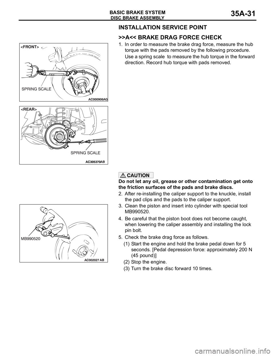
1. In order to measure the brake drag force, measure the hub
torque with the pads removed by the following procedure.
Use a spring scale to measure the hub torque in the forward
direction. Record hub torque with pads removed.
Do not let any oil, grease or other contamination get onto
the friction surfaces of the pads and brake discs.
2. After re-installing the caliper support to the knuckle, install
the pad clips and the pads to the caliper support.
3. Clean the piston and insert into cylinder with special tool
MB990520.
4. Be careful that the piston boot does not become caught,
when lowering the caliper assembly and installing the lock
pin bolt.
5. Check the brake drag force as follows.
(1) Start the engine and hold the brake pedal down for 5
seconds. [Pedal depression force: approximately 200 N
(45 pound)]
(2) Stop the engine.
(3) Turn the brake disc forward 10 times.
Page 1197 of 1500
DISC BRAKE ASSEMBLY
BASIC BRAKE SYSTEM35A-32
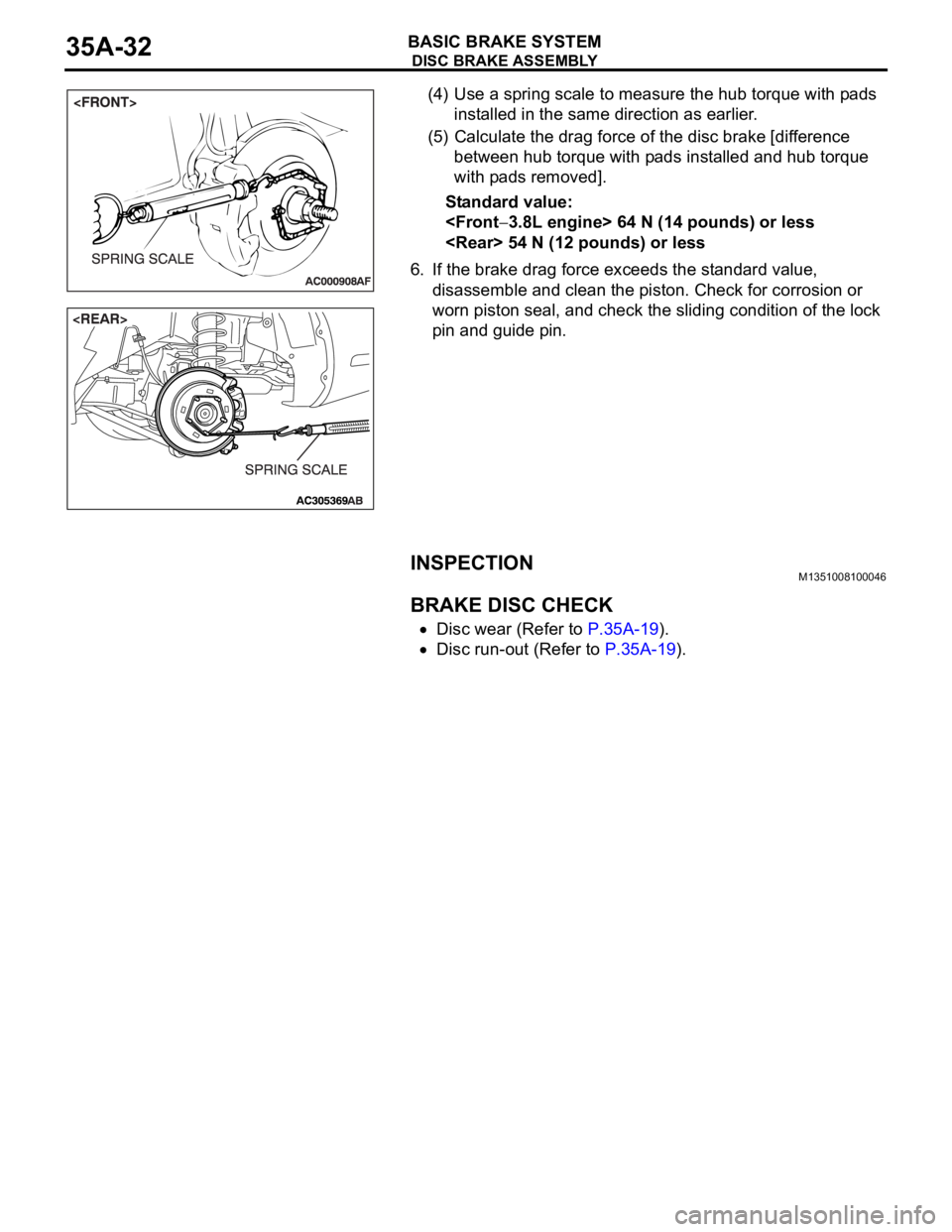
(4) Use a spring scale to measure the hub torque with pads
installed in the same direction as earlier.
(5) Calculate the drag force of the disc brake [difference
between hub torque with pads installed and hub torque
with pads removed].
Standard value:
6. If the brake drag force exceeds the standard value,
disassemble and clean the piston. Check for corrosion or
worn piston seal, and check the sliding condition of the lock
pin and guide pin.
INSPECTIONM1351008100046.
BRAKE DISC CHECK
Disc wear (Refer to P.35A-19).
Disc run-out (Refer to P.35A-19).
Page 1198 of 1500
DISC BRAKE ASSEMBLY
BASIC BRAKE SYSTEM35A-33
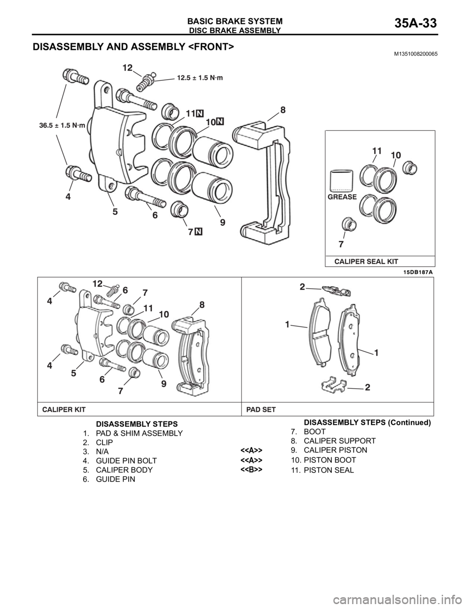
DISASSEMBLY AND ASSEMBLY
DISASSEMBLY STEPS
1. PAD & SHIM ASSEMBLY
2. CLIP
3. N/A
4. GUIDE PIN BOLT
5. CALIPER BODY
6. GUIDE PIN7. BOOT
8. CALIPER SUPPORT
<>9. CALIPER PISTON
<>10. PISTON BOOT
<>11. PISTON SEALDISASSEMBLY STEPS (Continued)
Page 1201 of 1500

DISC BRAKE ASSEMBLY
BASIC BRAKE SYSTEM35A-36
DISASSEMBLY AND ASSEMBLY
DISASSEMBLY STEPS
1. PAD & SHIM ASSEMBLY
2. CLIP
3. N/A
>>A<<4. REAR BRAKE BOLT
5. CALIPER BODY
6. GUIDE PIN7. PIN BOOT
8. CALIPER SUPPORT
<>9. PISTON
<>10. PISTON BOOT
<>11. PISTON SEAL
12. BLEEDERDISASSEMBLY STEPS (Continued)
Page 1203 of 1500
Page 1204 of 1500

DISC BRAKE ASSEMBLY
BASIC BRAKE SYSTEM35A-39
PAD WEAR CHECK
Always replace both brake pads on each wheel as
a set (both front wheels or both rear wheels). Fail-
ure to do so will result in uneven braking, which
may cause unreliable brake operation.
If there is significant difference in the thickness of
the pads on the left and right sides, check the slid-
ing condition of the piston and slide pins.
1. Measure thickness at the thinnest and most worn area of the
pad.
Standard value: 10 mm (0.39 inch)
Minimum limit: 2.0 mm (0.08 inch)
2. Replace the pad assembly if pad thickness is less than the
limit value.
Page 1205 of 1500

SPECIFICATIONS
BASIC BRAKE SYSTEM35A-40
SPECIFICATIONS
FASTENER TIGHTENING SPECIFICATIONSM1351009600390
GENERAL SPECIFICATIONSM1351000200362
ITEM SPECIFICATION
Brake line
Brake tube flare nut 15
2 Nm
Brake pedal
Brake booster nut 14
2 Nm
Brake pedal bolt 13
2 Nm
Front disc brake
Brake hose connector bolt 30
4 Nm
Caliper bleeder 12.5
1.5 Nm
Front brake assembly mounting bolt 100
10 Nm
Front brake bolt (guide pin bolt) 36.5
1.5 Nm
Master cylinder assembly and brake booster
Brake booster nut 14
2 Nm
Brake master cylinder mounting nut 25
2 Nm
Rear disc brake
Brake hose connector bolt 30
4 Nm
Caliper bleeder 12.5
1.5 Nm
Rear brake assembly mounting bolt 60
5 Nm
Rear brake bolt (guide pin bolt) 36.5
1.5 Nm
ITEM SPECIFICATION
Master
cylinderType Tandem type
I.D. mm 25.4
Brake
boosterType Vacuum type, tandem
Effective dia. of power
cylinder mm 205 + 230
Boosting ratio 6.5
Rear wheel hydraulic control method Electronic brake-force distribution (EBD)
Front brakes Type Floating caliper, Aluminium housing, 2 piston, ventilated disc
Disc effective dia
thickness
mm 296 28.0
Wheel cylinder I.D. mm 42.0 x 2
Pad thickness mm 10.0
Clearance adjustment Automatic