Interior light MITSUBISHI 380 2005 User Guide
[x] Cancel search | Manufacturer: MITSUBISHI, Model Year: 2005, Model line: 380, Model: MITSUBISHI 380 2005Pages: 1500, PDF Size: 47.87 MB
Page 492 of 1500

GENERAL DESCRIPTION
INTERIOR52A-3
GENERAL DESCRIPTIONM1521000100184
OPERATION
.
Seat belt warning system
If the driver turn the ignition switch to the "ON" posi-
tion without fastening the seat belt, the seat belt
warning light illuminates.
SEAT BELT DIAGNOSISM1523000700182
The seat belt warning system is controlled by the
Simplified Wiring System (SWS). For troubleshoot-
ing, refer to GROUP 54B, SWS diagnosis
P.54B-101.
SPECIAL TOOLSM1521000600327
TOOL TOOL NUMBER AND
NAMESUPERSESSION APPLICATION
MB990784
Ornament removerGeneral service
toolRemoval of switch, trim,
etc.
Page 508 of 1500

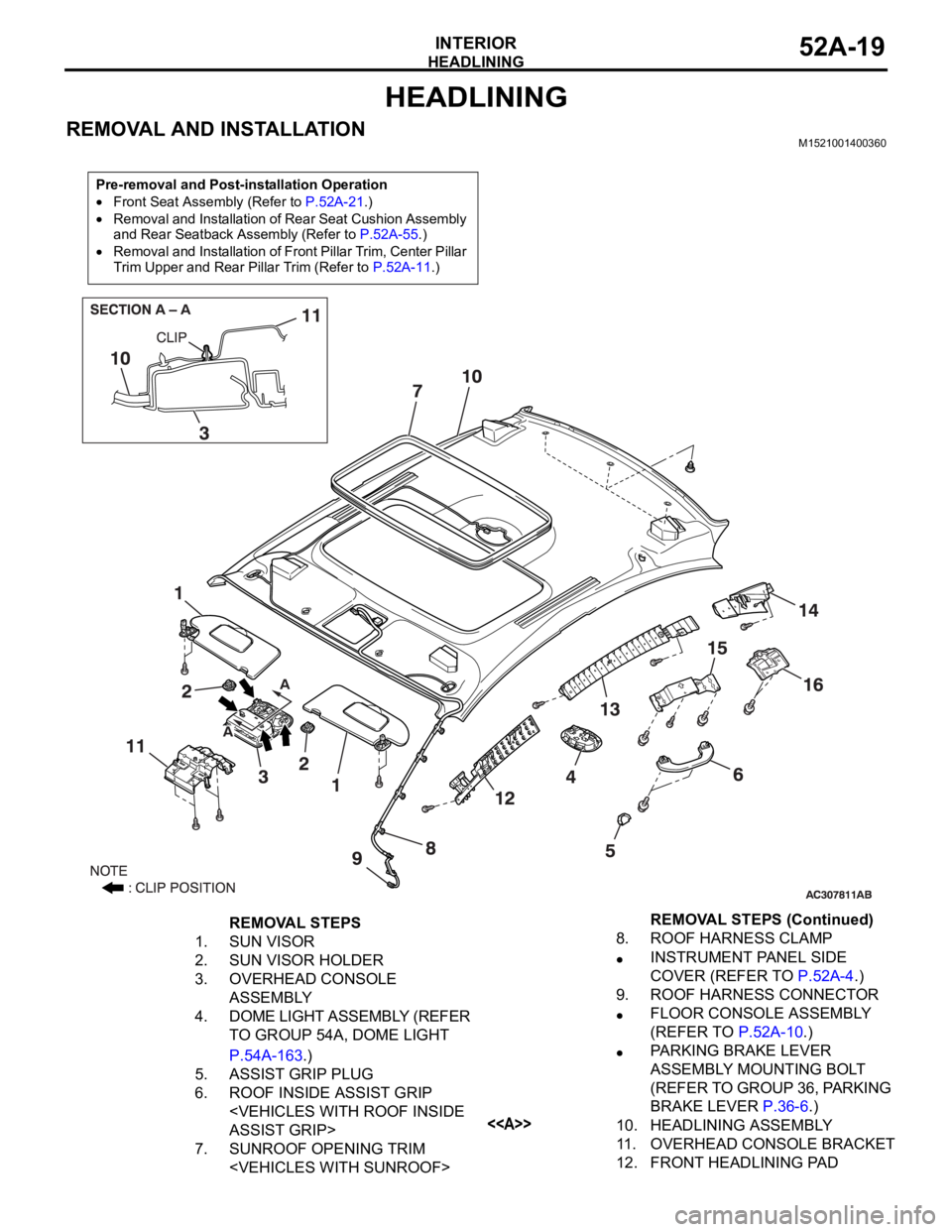
HEADLINING
INTERIOR52A-19
HEADLINING
REMOVAL AND INSTALLATIONM1521001400360
Pre-removal and Post-installation Operation
Front Seat Assembly (Refer to P.52A-21.)
Removal and Installation of Rear Seat Cushion Assembly
and Rear Seatback Assembly (Refer to P.52A-55.)
Removal and Installation of Front Pillar Trim, Center Pillar
Trim Upper and Rear Pillar Trim (Refer to P.52A-11.)
REMOVAL STEPS
1. SUN VISOR
2. SUN VISOR HOLDER
3. OVERHEAD CONSOLE
ASSEMBLY
4. DOME LIGHT ASSEMBLY (REFER
TO GROUP 54A, DOME LIGHT
P.54A-163.)
5. ASSIST GRIP PLUG
6. ROOF INSIDE ASSIST GRIP
7. SUNROOF OPENING TRIM
INSTRUMENT PANEL SIDE
COVER (REFER TO P.52A-4.)
9. ROOF HARNESS CONNECTOR
FLOOR CONSOLE ASSEMBLY
(REFER TO P.52A-10.)
PARKING BRAKE LEVER
ASSEMBLY MOUNTING BOLT
(REFER TO GROUP 36, PARKING
BRAKE LEVER P.36-6.)
<>10. HEADLINING ASSEMBLY
11. OVERHEAD CONSOLE BRACKET
12. FRONT HEADLINING PAD REMOVAL STEPS (Continued)
Page 531 of 1500

Page 834 of 1500

AUTO A/C DIAGNOSIS
HEATER, AIR CONDITIONING AND VENTILATION55-133
DATA LIST REFERENCE TABLEM1554005100136
MUT-III
DIAGNOSTIC
TOOL DISPLAYITEM
NO.INSPECTION ITEM INSPECTION REQUIREMENT NORMAL VALUE
Inside
temperature
sensor59 Interior temperature
sensorIgnition switch: ON Inside air
temperature and
temperature
displayed on the
diagnostic tool are
identical.
Outside
temperature
sensor58 Outside temperature
sensorIgnition switch: ON Outside air
temperature and
temperature
displayed on the
diagnostic tool are
identical.
Air thermo sensor 20 Air thermo sensor Ignition switch: ON The temperature
measured behind
the evaporator
matches the
displayed value on
the diagnostic tool
while the engine is
cold.
Pressure sensor 61 A/C pressure sensor Ignition switch: ON Measured refrigerant
pressure is nearly
equal to the value
shown on the
diagnostic tool
(MPa).
Water
temperature
sensor62 Engine coolant
temperature sensor
(Data received by
CAN
Communication)Ignition switch: ON Engine coolant
temperature and
temperature
displayed on the
diagnostic tool are
identical.
Photo sensor 67 Photo sensor Ignition switch: ON Amount of light is
proportional to
voltage displayed on
the diagnostic tool.
Air mix
potentiometer63 Air mixing damper
control motor
potentiometerIgnition switch: ON Damper
positionOpening degree (V)
MAX. HOT Approx. 5
MAX. COOL Approx. 0
Air mix
potentiometer
(Target)64 Target value for air
mixing damper
control motor
potentiometerIgnition switch: ON Damper
positionOpening degree (V)
MAX. HOT Approx. 5
MAX. COOL Approx. 0
Page 839 of 1500

AUTO A/C DIAGNOSIS
HEATER, AIR CONDITIONING AND VENTILATION55-138
16 Potentiometer power supply Ignition switch: ON 5 V
17 Power transistor (BASE) When the blower speed
selection dial shows Maximum
air volume.1 V
18 Power transistor
(COLLECTOR)When the blower speed
selection dial shows Maximum
air volume.12.1 V
19 Photo sensor Ignition switch: ON 5 V
20 Sensors and potentiometers
groundAlways 0 V
21 Mode selection damper control
motor potentiometer inputWhen the damper is moved to
the FACE position. 4 V
22 Interior temperature sensor Ignition switch: ON 5 V
23 Ambient temperature sensor
inputWhen sensor temperature is
25
C (77F) [4 k]1.9 V
24 Air thermo sensor input When sensor temperature is
25
C (77F) [1.5 k]2.2 V
25 Photo sensor ground Ignition switch: ON 0 V
26 A/C pressure sensor at 2.6 MPa 3.9 V
27 Ground Always 0 V
28 Power supply to the ignition
switch (IG2)Ignition switch: ON Battery positive voltage
29 Air mixing damper control motor
potentiometer inputWhen the damper door is
moved to the MAX. HOT
position.1.4 V
30 Illumination ground Always 0 V
31 ILL power supply Lighting switch: ON Battery positive voltage
34 A/C pressure sensor ground Always 0 V
36 Power supply to the ignition
switch (ACC)Ignition switch: ON Battery positive voltage TERMINAL
NO.CHECK ITEM CHECKING REQUIREMENTS NORMAL CONDITION