TCL MITSUBISHI 380 2005 User Guide
[x] Cancel search | Manufacturer: MITSUBISHI, Model Year: 2005, Model line: 380, Model: MITSUBISHI 380 2005Pages: 1500, PDF Size: 47.87 MB
Page 674 of 1500
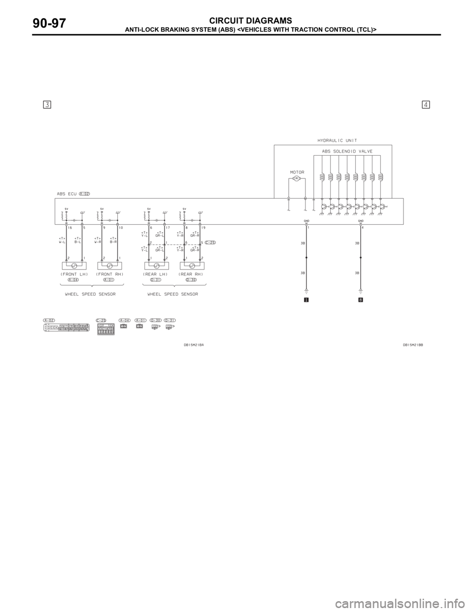
ANTI-LOCK BRAKING SYSTEM (ABS)
CIRCUIT DIAGRAMS90-97
Page 675 of 1500
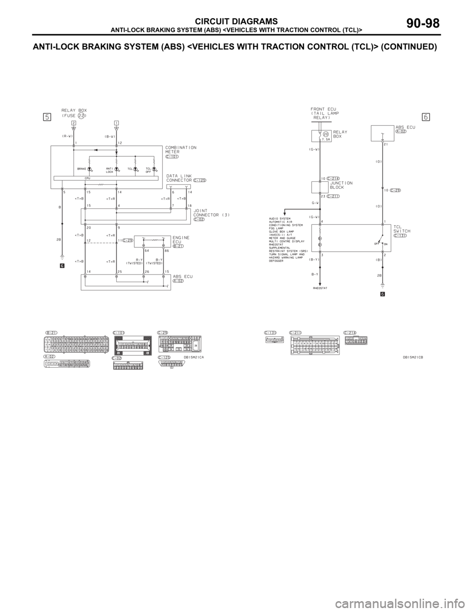
ANTI-LOCK BRAKING SYSTEM (ABS)
CIRCUIT DIAGRAMS90-98
ANTI-LOCK BRAKING SYSTEM (ABS)
Page 893 of 1500
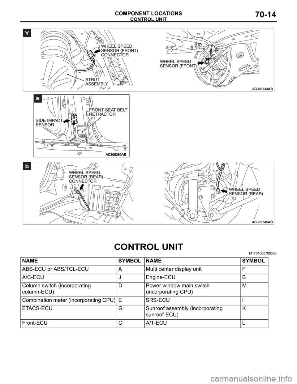
CONTROL UNIT
COMPONENT LOCATIONS70-14
CONTROL UNITM1701000700360
NAME SYMBOL NAME SYMBOL
ABS-ECU or ABS/TCL-ECU A Multi center display unit F
A/C-ECU J Engine-ECU B
Column switch (incorporating
column-ECU)D Power window main switch
(incorporating CPU)M
Combination meter (incorporating CPU) E SRS-ECU I
ETACS-ECU G Sunroof assembly (incorporating
sunroof-ECU)K
Front-ECU C A/T-ECU L
Page 1224 of 1500
HOW TO USE THIS MANUAL
GENERAL00-3
HOW TO USE THIS MANUALM1001000100897
MAINTENANCE, REPAIR AND
SERVICING EXPLANATIONS
This manual provides explanations, etc. concerning
procedures for the inspection, maintenance, repair
and servicing of the subject model. Unless otherwise
specified, each service procedure covers all models.
Procedures covering specific models are identified
by the model codes, or similar designation (engine
type, transaxle type, etc). A description of these des-
ignations is covered in this manual under "VEHICLE
IDENTIFICATION."
.
ON-VEHICLE SERVICE
The "ON-VEHICLE SERVICE" section has proce-
dures for performing inspections and adjustments of
particularly important components. These proce-
dures are done with regard to maintenance and ser-
vicing, but other inspections (looseness, play,
cracking, damage, etc.) must also be performed.
.
SERVICE PROCEDURES
The service steps are arranged in numerical order.
Attention to be paid in performing vehicle service are
described in detail in SERVICE POINTS.
DEFINITION OF TERMS
.
STANDARD VALUE
Indicates the value used as the standard for judging
whether or not a part or adjustment is correct.
.
LIMIT
Shows the maximum or minimum value for judging
whether or not a part or adjustment is acceptable.
.
REFERENCE VALUE
Indicates the adjustment value prior to starting the
work (presented in order to facilitate assembly and
adjustment procedures, and so they can be com-
pleted in a shorter time).
.
DANGER, WARNING, AND CAUTION
DANGER, WARNING, and CAUTION call special
attention to a necessary action or to an action that
must be avoided. The differences among DANGER,
WARNING, and CAUTION are as follows:
If a DANGER is not followed, the result is severe
bodily harm or even death.
If a WARNING is not followed, the result could be
bodily injury.
If a CAUTION is not followed, the result could be
damage to the vehicle, vehicle components or
service equipment.
TIGHTENING TORQUE INDICATION
The tightening torque indicates a median and its tol-
erance by a unit of N
m (in-lb.) or Nm (ft.-lb.). For
fasteners with no assigned torque value, refer to
P.00-32.
SPECIAL TOOL NOTE
Only MMC special tool part numbers are called out in
the repair sections of this manual. Please refer to the
special tool cross-reference chart located at the
beginning of each group, for the special tool number
that is available in your market.
ABBREVIATIONS
The following abbreviations are used in this manual
for classification of model types:
A/T:Automatic transaxle, or models equipped with
automatic transaxle.
MPI: Multipoint fuel injection, or engines equipped
with multiport fuel injection.
A/C: Air conditioning.
3.8L engine: 3.8 litre <6G75> engine, or a model
equipped with such an engine.
ABS: Anti-lock Braking System
TCL: Traction Control System
ECU: Electronic Control Unit
V.C.I.: Vehicle Communication Interface
SWS: Simplified Wiring System
CAN: Controller Area Network
M/T: Manual Transmission
SRS: Supplemental Restraint System
Page 1247 of 1500
TOWING AND HOISTING
GENERAL00-26
TOWING AND HOISTINGM1001000800380
TOWING THE VEHICLE BY A TOW TRUCK
.
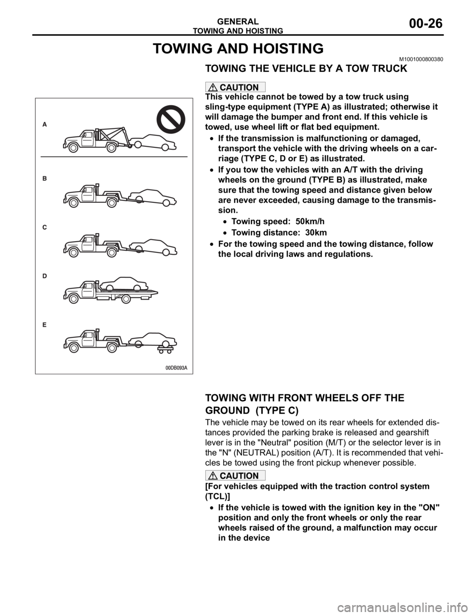
This vehicle cannot be towed by a tow truck using
sling-type equipment (TYPE A) as illustrated; otherwise it
will damage the bumper and front end. If this vehicle is
towed, use wheel lift or flat bed equipment.
If the transmission is malfunctioning or damaged,
transport the vehicle with the driving wheels on a car-
riage (TYPE C, D or E) as illustrated.
If you tow the vehicles with an A/T with the driving
wheels on the ground (TYPE B) as illustrated, make
sure that the towing speed and distance given below
are never exceeded, causing damage to the transmis-
sion.
Towing speed: 50km/h
Towing distance: 30km
For the towing speed and the towing distance, follow
the local driving laws and regulations.
.
TOWING WITH FRONT WHEELS OFF THE
GROUND (TYPE C)
The vehicle may be towed on its rear wheels for extended dis-
tances provided the parking brake is released and gearshift
lever is in the "Neutral" position (M/T) or the selector lever is in
the "N" (NEUTRAL) position (A/T). It is recommended that vehi-
cles be towed using the front pickup whenever possible.
[For vehicles equipped with the traction control system
(TCL)]
If the vehicle is towed with the ignition key in the "ON"
position and only the front wheels or only the rear
wheels raised of the ground, a malfunction may occur
in the device
.
Page 1280 of 1500
13C-1
GROUP 13C
TRACTION
CONTROL SYSTEM
(TCL)
CONTENTS
GENERAL DESCRIPTION. . . . . . . . .13C-2
TRACTION CONTROL SYSTEM (TCL)
DIAGNOSIS . . . . . . . . . . . . . . . . . . . .13C-3
INTRODUCTION TO TRACTION CONTROL
SYSTEM (TCL) DIAGNOSIS . . . . . . . . . . . 13C-3
TROUBLESHOOTING STRATEGY . . . . . . 13C-3
DIAGNOSIS FUNCTION. . . . . . . . . . . . . . . 13C-3
DIAGNOSTIC TROUBLE CODE CHART . . 13C-8
DIAGNOSTIC TROUBLE CODE
PROCEDURES . . . . . . . . . . . . . . . . . . . . . . 13C-10
SYMPTOM CHART. . . . . . . . . . . . . . . . . . . 13C-23
SYMPTOM PROCEDURES . . . . . . . . . . . . 13C-23
DATA LIST REFERENCE TABLE . . . . . . . 13C-36
ACTUATOR TEST REFERENCE TABLE. . 13C-37
CHECK AT ABS/TCL-ECU RESISTANCE
AND TERMINAL VOLTAGE . . . . . . . . . . . . 13C-38RESISTANCE AND CONTINUITY
BETWEEN ABS-ECU AND WHEEL SPEED
SENSOR . . . . . . . . . . . . . . . . . . . . . . . . . . . 13C-39
VOLTAGE AND SIGNAL CHECK AT
ABS-ECU USING AN OSCILLOSCOPE . . . 13C-41
SPECIAL TOOLS . . . . . . . . . . . . . . . .13C-45
ON-VEHICLE SERVICE . . . . . . . . . . .13C-47
TCL INDICATOR LIGHT CHECK . . . . . . . . 13C-47
TCL OPERATION CHECK . . . . . . . . . . . . . 13C-47
TCL SWITCH CHECK . . . . . . . . . . . . . . . . . 13C-48
WHEEL SPEED SENSOR CHECK . . . . . . . 13C-48
TCL SWITCH . . . . . . . . . . . . . . . . . . .13C-49
REMOVAL AND INSTALLATION . . . . . . . . 13C-49
WHEEL SPEED SENSOR . . . . . . . . .13C-49
REMOVAL AND INSTALLATION . . . . . . . . 13C-49
ABS/TCL-ECU . . . . . . . . . . . . . . . . . .13C-49
REMOVAL AND INSTALLATION . . . . . . . . 13C-49
Page 1281 of 1500
GENERAL DESCRIPTION
TRACTION CONTROL SYSTEM (TCL)13C-2
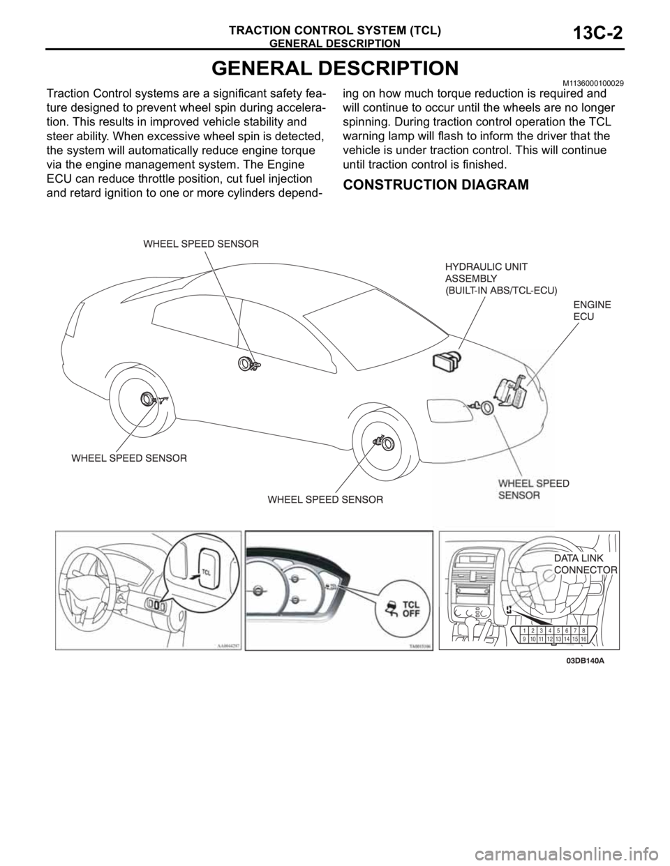
GENERAL DESCRIPTIONM1136000100029
Traction Control systems are a significant safety fea-
ture designed to prevent wheel spin during accelera-
tion. This results in improved vehicle stability and
steer ability. When excessive wheel spin is detected,
the system will automatically reduce engine torque
via the engine management system. The Engine
ECU can reduce throttle position, cut fuel injection
and retard ignition to one or more cylinders depend-ing on how much torque reduction is required and
will continue to occur until the wheels are no longer
spinning. During traction control operation the TCL
warning lamp will flash to inform the driver that the
vehicle is under traction control. This will continue
until traction control is finished.
CONSTRUCTION DIAGRAM
91011
1213141516 12345
678
Page 1282 of 1500
TRACTION CONTROL SYSTEM (TCL) DIAGNOSIS
TRACTION CONTROL SYSTEM (TCL)13C-3
TRACTION CONTROL SYSTEM (TCL) DIAGNOSIS
INTRODUCTION TO TRACTION CONTROL SYSTEM (TCL) DIAGNOSISM1136004600026
TCL Diagnostic Trouble Code Detection
Conditions
TCL diagnostic trouble codes (TCL DTCs) are set
under different conditions, depending on the mal-
function detected. Most TCL DTCs will only be set
during vehicle operation. Some TCL DTCs will also
be set during the TCL self-check immediately after
the engine is started. When you check if an TCL DTC will be displayed again after the DTC has been
erased, you should recreate the TCL DTC set condi-
tions. Depending on the detection timing and set
conditions for the specific TCL DTC, you must either
drive the vehicle or turn the engine off and restart it.
To set the proper conditions for that DTC again, refer
to "TCL DTC SET CONDITIONS" for each TCL DTC
that you are trying to reset.
TROUBLESHOOTING STRATEGYM1136003100062
Use these steps to plan your diagnostic strategy. If
you follow them carefully, you will check most of the
possible causes of a TCL problem.
1. Gather information from the customer.
2. Verify that the condition described by the
customer exists.
3. Check the vehicle for any TCL DTC. (Refer to
P.13C-3, Diagnosis Function
How to Read and
Erase Diagnostic Trouble Codes).
4. If you can verify the condition but no TCL DTCs
are set, and the malfunction may be intermittent.
(Refer to GROUP 00, How to Use
Troubleshooting/Inspection Service Points
How
to Cope with Intermittent Malfunctions P.00-14).
5. If you can verify the condition but there is no TCL
DTCs, or the system cannot communicate with
diagnostic tool MB991958 (MUT-III sub
assembly), and find the fault. (Refer to P.13C-23,
Symptom Chart).6. If there is a TCL DTC, record the number of the
code, then erase the code from vehicle memory
using the diagnostic tool MB991958 (MUT-III sub
assembly). (Refer to P.13C-3, Diagnosis Function
How to Read and Erase Diagnostic Trouble
Codes).
7. Re-create the TCL DTC set conditions to see if
the same TCL DTC will set again. (Refer to
P.13C-3, Diagnosis Function
How to Read and
Erase Diagnostic Trouble Codes).
If the same TCL DTC sets again, perform the
diagnostic procedures for the set code. (Refer to
P.13C-8, Diagnostic Trouble Code Chart).
NOTE: If the ABS-8 ECU or the active wheel
speed sensor are disconnected, or if the wir-
ing is an open/ short circuit, the ABS 8 ECU
will shut off power supply to the respective
wheel speed sensor. All other wheel speed
sensors will operate normally. To restore the
power supply, the ignition switch must be
turned to the "OFF" position then to the "ON"
position again.
DIAGNOSIS FUNCTIONM1136003200025
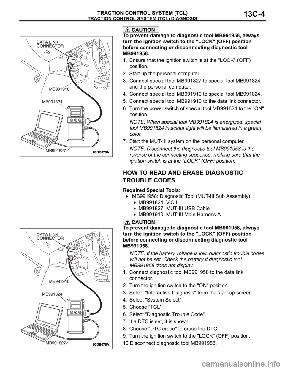
HOW TO CONNECT THE DIAGNOSTIC TOOL
(MUT-III)
Required Special Tools:
MB991958: Diagnostic Tool (MUT-III Sub Assembly)
MB991824: Vehicle Communication Interface (V.C.I.)
MB991827: MUT-III USB Cable
MB991910: MUT-III Main Harness A
Page 1283 of 1500
TRACTION CONTROL SYSTEM (TCL) DIAGNOSIS
TRACTION CONTROL SYSTEM (TCL)13C-4
To prevent damage to diagnostic tool MB991958, always
turn the ignition switch to the "LOCK" (OFF) position
before connecting or disconnecting diagnostic tool
MB991958.
1. Ensure that the ignition switch is at the "LOCK" (OFF)
position.
2. Start up the personal computer.
3. Connect special tool MB991827 to special tool MB991824
and the personal computer.
4. Connect special tool MB991910 to special tool MB991824.
5. Connect special tool MB991910 to the data link connector.
6. Turn the power switch of special tool MB991824 to the "ON"
position.
NOTE: When special tool MB991824 is energized, special
tool MB991824 indicator light will be illuminated in a green
color.
7. Start the MUT-III system on the personal computer.
NOTE: Disconnect the diagnostic tool MB991958 is the
reverse of the connecting sequence, making sure that the
ignition switch is at the "LOCK" (OFF) position.
HOW TO READ AND ERASE DIAGNOSTIC
TROUBLE CODES
Required Special Tools:
MB991958: Diagnostic Tool (MUT-III Sub Assembly)
MB991824: V.C.I.
MB991827: MUT-III USB Cable
MB991910: MUT-III Main Harness A
To prevent damage to diagnostic tool MB991958, always
turn the ignition switch to the "LOCK" (OFF) position
before connecting or disconnecting diagnostic tool
MB991958.
NOTE: If the battery voltage is low, diagnostic trouble codes
will not be set. Check the battery if diagnostic tool
MB991958 does not display.
1. Connect diagnostic tool MB991958 to the data link
connector.
2. Turn the ignition switch to the "ON" position.
3. Select "Interactive Diagnosis" from the start-up screen.
4. Select "System Select".
5. Choose "TCL" .
6. Select "Diagnostic Trouble Code".
7. If a DTC is set, it is shown.
8. Choose "DTC erase" to erase the DTC.
9. Turn the ignition switch to the "LOCK" (OFF) position.
10.Disconnect diagnostic tool MB991958.
Page 1284 of 1500
TRACTION CONTROL SYSTEM (TCL) DIAGNOSIS
TRACTION CONTROL SYSTEM (TCL)13C-5
HOW TO READ DATA LIST
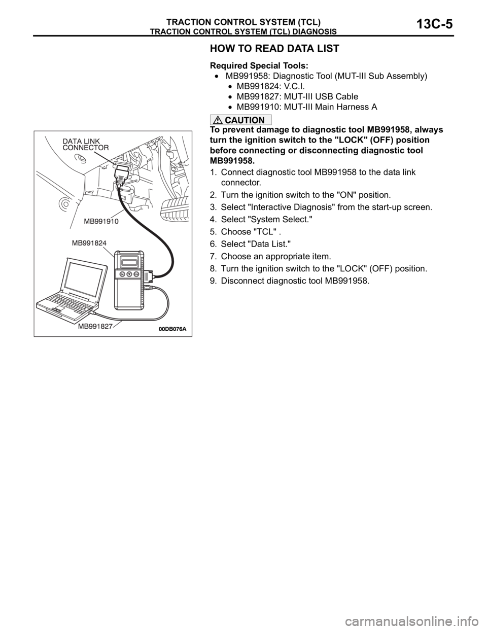
Required Special Tools:
MB991958: Diagnostic Tool (MUT-III Sub Assembly)
MB991824: V.C.I.
MB991827: MUT-III USB Cable
MB991910: MUT-III Main Harness A
To prevent damage to diagnostic tool MB991958, always
turn the ignition switch to the "LOCK" (OFF) position
before connecting or disconnecting diagnostic tool
MB991958.
1. Connect diagnostic tool MB991958 to the data link
connector.
2. Turn the ignition switch to the "ON" position.
3. Select "Interactive Diagnosis" from the start-up screen.
4. Select "System Select."
5. Choose "TCL" .
6. Select "Data List."
7. Choose an appropriate item.
8. Turn the ignition switch to the "LOCK" (OFF) position.
9. Disconnect diagnostic tool MB991958.