Tail light MITSUBISHI 380 2005 Owner's Manual
[x] Cancel search | Manufacturer: MITSUBISHI, Model Year: 2005, Model line: 380, Model: MITSUBISHI 380 2005Pages: 1500, PDF Size: 47.87 MB
Page 394 of 1500

SYMPTOM PROCEDURES
SIMPLIFIED WIRING SYSTEM (SWS)54B-394
INSPECTION PROCEDURE K-6: Interior Light: The door ajar indicator lamps do not illuminate or go
out normally
NOTE: This troubleshooting procedure requires the
use of diagnostic tool MB991958 and SWS monitor
kit MB991813. For details on how to use the SWS
monitor, refer to "How to connect SWS monitor
P.54B-13."
.
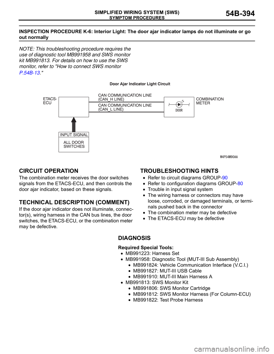
CIRCUIT OPERATION
The combination meter receives the door switches
signals from the ETACS-ECU, and then controls the
door ajar indicator, based on these signals.
.
TECHNICAL DESCRIPTION (COMMENT)
If the door ajar indicator does not illuminate, connec-
tor(s), wiring harness in the CAN bus lines, the door
switches, the ETACS-ECU, or the combination meter
may be defective.
.
TROUBLESHOOTING HINTS
Refer to circuit diagrams GROUP-90
Refer to configuration diagrams GROUP-80
Trouble in input signal system
The wiring harness or connectors may have
loose, corroded, or damaged terminals, or termi-
nals pushed back in the connector
The combination meter may be defective
The ETACS-ECU may be defective
DIAGNOSIS
Required Special Tools:
MB991223: Harness Set
MB991958: Diagnostic Tool (MUT-III Sub Assembly)
MB991824: Vehicle Communication Interface (V.C.I.)
MB991827: MUT-III USB Cable
MB991910: MUT-III Main Harness A
MB991813: SWS Monitor Kit
MB991806: SWS Monitor Cartridge
MB991812: SWS Monitor Harness (For Column-ECU)
MB991822: Test Probe Harness
Page 398 of 1500

SYMPTOM PROCEDURES
SIMPLIFIED WIRING SYSTEM (SWS)54B-398
INSPECTION PROCEDURE K-7: Interior Light: The seat belt warning lamp do not illuminate or go out
normally
NOTE: This troubleshooting procedure requires the
use of diagnostic tool MB991958 and SWS monitor
kit MB991813. For details on how to use the SWS
monitor, refer to "How to connect SWS monitor
P.54B-13."
.
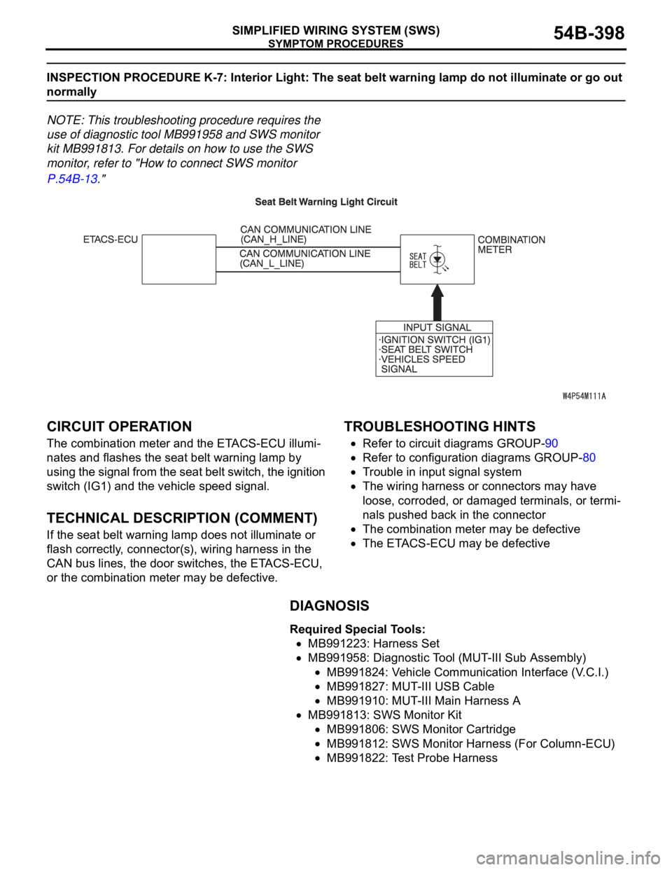
CIRCUIT OPERATION
The combination meter and the ETACS-ECU illumi-
nates and flashes the seat belt warning lamp by
using the signal from the seat belt switch, the ignition
switch (IG1) and the vehicle speed signal.
.
TECHNICAL DESCRIPTION (COMMENT)
If the seat belt warning lamp does not illuminate or
flash correctly, connector(s), wiring harness in the
CAN bus lines, the door switches, the ETACS-ECU,
or the combination meter may be defective.
.
TROUBLESHOOTING HINTS
Refer to circuit diagrams GROUP-90
Refer to configuration diagrams GROUP-80
Trouble in input signal system
The wiring harness or connectors may have
loose, corroded, or damaged terminals, or termi-
nals pushed back in the connector
The combination meter may be defective
The ETACS-ECU may be defective
DIAGNOSIS
Required Special Tools:
MB991223: Harness Set
MB991958: Diagnostic Tool (MUT-III Sub Assembly)
MB991824: Vehicle Communication Interface (V.C.I.)
MB991827: MUT-III USB Cable
MB991910: MUT-III Main Harness A
MB991813: SWS Monitor Kit
MB991806: SWS Monitor Cartridge
MB991812: SWS Monitor Harness (For Column-ECU)
MB991822: Test Probe Harness
Page 420 of 1500

INPUT SIGNAL PROCEDURES
SIMPLIFIED WIRING SYSTEM (SWS)54B-420
INSPECTION PROCEDURE M-5: Column Switch: ETACS-ECU does not receive any signal from the
taillamp switch, the headlamp switch, the passing lamp switch, the dimmer switch or the turn-signal
lamp switch.
NOTE: This troubleshooting procedure requires the
use of diagnostic tool MB991958 and SWS monitor
kit MB991813. For details on how to use the SWS
monitor, refer to "How to connect SWS monitor
P.54B-13."
.
CIRCUIT OPERATION
The ETACS-ECU operates the following equipment
or functions according to signal from the column
switch (turn-signal lamp and lighting switch):
Light reminder tone alarm function
Turn-signal lamp buzzer
Headlamp
Turn-signal lamp
High-beam indicator
Turn-signal indicators
.
TECHNICAL DESCRIPTION (COMMENT)
If the signal is not normal, the equipment or functions
described in "CIRCUIT OPERATION" do not work
normally. If the signal is not normal, the column
switch (turn-signal lamp and lighting switch) or the
ETACS-ECU may be defective.
.
TROUBLESHOOTING HINTS
Refer to circuit diagrams GROUP-90
Refer to configuration diagrams GROUP-80
The column switch (turn-signal lamp and lighting
switch) may be defective
The ETACS-ECU may be defective
DIAGNOSIS
Required Special Tools:
MB991223: Harness Set
MB991958: Diagnostic Tool (MUT-III Sub Assembly)
MB991824: Vehicle Communication Interface (V.C.I.)
MB991827: MUT-III USB Cable
MB991910: MUT-III Main Harness A
MB991813: SWS Monitor Kit
MB991806: SWS Monitor Cartridge
MB991812: SWS Monitor Harness (For Column-ECU)
MB991822: Test Probe Harness
Page 422 of 1500

INPUT SIGNAL PROCEDURES
SIMPLIFIED WIRING SYSTEM (SWS)54B-422
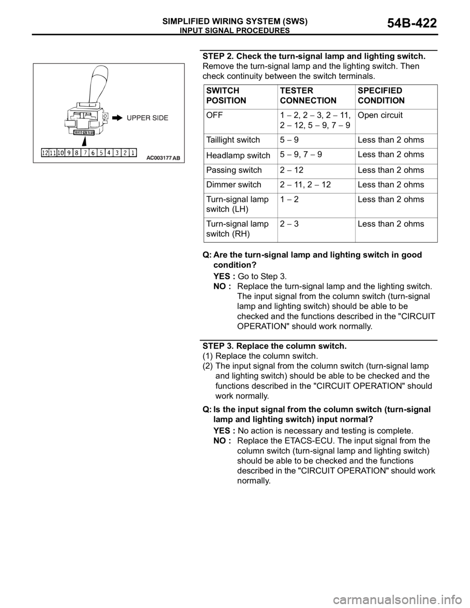
STEP 2. Check the turn-signal lamp and lighting switch.
Remove the turn-signal lamp and the lighting switch. Then
check continuity between the switch terminals.
Q: Are the turn-signal lamp and lighting switch in good
condition?
YES : Go to Step 3.
NO : Replace the turn-signal lamp and the lighting switch.
The input signal from the column switch (turn-signal
lamp and lighting switch) should be able to be
checked and the functions described in the "CIRCUIT
OPERATION" should work normally.
STEP 3. Replace the column switch.
(1) Replace the column switch.
(2) The input signal from the column switch (turn-signal lamp
and lighting switch) should be able to be checked and the
functions described in the "CIRCUIT OPERATION" should
work normally.
Q: Is the input signal from the column switch (turn-signal
lamp and lighting switch) input normal?
YES : No action is necessary and testing is complete.
NO : Replace the ETACS-ECU. The input signal from the
column switch (turn-signal lamp and lighting switch)
should be able to be checked and the functions
described in the "CIRCUIT OPERATION" should work
normally. SWITCH
POSITIONTESTER
CONNECTIONSPECIFIED
CONDITION
OFF 1
2, 2 3, 2 11,
2
12, 5 9, 7 9Open circuit
Taillight switch 5
9 Less than 2 ohms
Headlamp switch5
9, 7 9 Less than 2 ohms
Passing switch 2
12 Less than 2 ohms
Dimmer switch 2
11, 2 12 Less than 2 ohms
Turn-signal lamp
switch (LH)1
2 Less than 2 ohms
Turn-signal lamp
switch (RH)2
3 Less than 2 ohms
Page 484 of 1500

CHECK AT ECU TERMINAL
SIMPLIFIED WIRING SYSTEM (SWS)54B-484
FRONT-ECU
NOTE: Terminal voltages cannot be measured as the
front-ECU is installed directly on the relay box.
Therefore, this information is only for reference.
TERMINAL
NO.INSPECTION ITEM INSPECTION CONDITION NORMAL VALUE
1 Output to fog lamp relay When the fog lamps are on Battery positive voltage
2 Output to headlamp (high-beam) When headlights (high-beam)
are onBattery positive voltage
3, 4 Battery power supply (for
headlamp)Always Battery positive voltage
5 Battery power supply (for
taillamp)Always Battery positive voltage
6 Output to headlamp (low-beam) When headlights (low-beam) are
onBattery positive voltage
7 Battery power supply (for ECU) Always Battery positive voltage
8 Output to taillamps When taillamps are on Battery positive voltage
9
11
21 Output to windshield washer When windshield washer is on Battery positive voltage
22 SWS communication line Always 0
12 V (pulse signal)
23 Input of automatic stop signal to
windshield wiperWhen windshield wiper is on Battery positive voltage
24 Power supply to ignition switch
(ACC)Ignition switch: "ACC" Battery positive voltage
25 Input of backup signal from
headlamp switchHeadlamp switch: ON0 V
26 Input of backup signal to
windshield wiperWindshield low-speed wiper
switch or windshield high-speed
wiper switch: ON0 V
27 Output to windshield wiper
(low-speed)When windshield wiper is on (at
low speed)Battery positive voltage
28 Output to windshield wiper
(high-speed)When windshield wiper is on (at
high speed)Battery positive voltage
30 Power supply to ignition switch
(IG2)Ignition switch: "ON" Battery positive voltage
31 Ground Always 0 V
Page 590 of 1500

CENTRALISED JUNCTION
CIRCUIT DIAGRAMS90-13
19 Front-ECU (Field
effect transistor for
headlamp: Low)Fuse 10 Red Headlamp (LH) and headlamp (Low:
LH)
20 Front-ECU (Taillamp
relay)7.5 Brown A/C-ECU, A/T selector lever position
illumination lamp, combination meter,
fog lamp switch, headlamp (RH),
glove box lamp, hazard warning lamp
switch, multi-center display unit,
radio, CD player, rear combination
lamp (RH), rheostat and TCL switch
21 7.5 Brown Headlamp (LH), license plate lamp
and rear combination lamp (LH)
22 Battery/Alternator
(Fusible link No.27)15 Blue A/C-ECU, column switch,
combination meter, ETACS-ECU,
front-ECU, key reminder switch, multi-
center display unit, radio, CD player,
and vanity mirror lamp
23 Ignition switch (ACC) 10 Red A/C-ECU, accessory socket relay,
ETACS-ECU, multi-center display
unit, radio, CD player.
24 Battery/Alternator
(Fusible link No.27)15 Blue Fuel pump module
25 Ignition switch (ACC) 30 Green Front-ECU and windshield wiper
motor
26 Battery/Alternator
(Fusible link No.27)Fusible
link20 Light blue Anti-lock braking system(solenoid
valve)
27
Alternator120
Battery, front-ECU, fusible link Nos.1,
2, 3, 4, 5 and 26 and fuse Nos.6, 7, 8,
9, 10, 11, 13, 14, 15, 22 and 24 (in
relay box) NO. POWER SUPPLY
CIRCUITNAME RATED
CAPACITY (A)HOUSING
COLOURLOAD CIRCUIT
Page 1134 of 1500

KEYLESS ENTRY SYSTEM
BODY42-67
KEYLESS ENTRY SYSTEM
GENERAL DESCRIPTIONBGBJABIE
Antenna and receiver are incorporated in the
ETACS-ECU.
ID code can be registered by using Diagnostic
tool (MUT-III).
Transmitter is a key holder type, which incorpo-
rates lock button, unlock button, trunk button and
panic button
When the transmitter unlock button is pressed
once, the driver's door will be unlocked. If the but-
ton is pressed twice, all the doors will be
unlocked. The adjustment function also allows
you to open all the doors by pressing the unlock
button only once. For further details on using the
multi-center display to adjust the unlock opera-
tion, refer to GROUP 54B, On-vehicle Service
P.54B-486.
When the transmitter is operated, the answer-
back function will work as follows:
The answerback operation can be altered as fol-
lows:NOTE: Enabling/disabling the hazard warning
light flashing, the horn sounding in accordance
with the answerback function. For further details
on using the transmitter to adjust answerback,
P.42-72 see the section below. For further details
on using the multi-center display to adjust
answerback, refer to GROUP 54B, On-vehicle
Service P.54B-486. ITEM OPERATION
DOORS LOCKED DOORS UNLOCKED
Dome light Flashes once Illuminates for 15 seconds
Turn-signal lights (RH and LH) Flashes once Flashes twice
Horn Sounds once when the lock button
is pressed with all the doors locked-
ITEM ADJUSTMENT ITEM ADJUSTMENT DETAIL
Keyless entry system
confirmation by turn
signal lightsAdjustment of hazard answerback
when the transmitter is used to
lock doorsWhen adjusting hazard answerback after the
doors are locked with the transmitter, the
following flashing conditions can be selected.
a. Flash (default)
b. No flash
Adjustment of hazard answerback
when the transmitter is used to
unlock doorsWhen adjusting hazard answerback after the
doors are unlocked with the transmitter, the
following flashing conditions can be selected.
a. Flash (default)
b. No flash
Keyless entry system
confirmation by hornAdjustment of horn answerback
when the transmitter is used to
lock doorsWhen adjusting horn answerback after the
doors are locked with the transmitter, the
following horn conditions can be selected.
a. Horn sounds
b. Horn sounds if doors are already locked
(default)
c. Horn does not sound