ECU MITSUBISHI 380 2005 Workshop Manual
[x] Cancel search | Manufacturer: MITSUBISHI, Model Year: 2005, Model line: 380, Model: MITSUBISHI 380 2005Pages: 1500, PDF Size: 47.87 MB
Page 910 of 1500
HOW TO DIAGNOSE
GENERAL
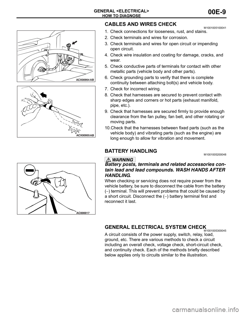
CABLES AND WIRES CHECKM1001005100041
1. Check connections for looseness, rust, and stains.
2. Check terminals and wires for corrosion.
3. Check terminals and wires for open circuit or impending
open circuit.
4. Check wire insulation and coating for damage, cracks, and
wear.
5. Check conductive parts of terminals for contact with other
metallic parts (vehicle body and other parts).
6. Check grounding parts to verify that there is complete
continuity between attaching bolt(s) and vehicle body.
7. Check for incorrect wiring.
8. Check that harnesses are secured to prevent contact with
sharp edges and corners or hot parts (exhaust manifold,
pipe, etc.).
9. Check that harnesses are secured firmly to provide enough
clearance from the fan pulley, fan belt, and other rotating or
moving parts.
10.Check that the harnesses between fixed parts (such as the
vehicle body) and vibrating parts (such as the engine) are
long enough to allow for vibration and movement.
BATTERY HANDLINGM1001005200048
Battery posts, terminals and related accessories con-
tain lead and lead compounds. WASH HANDS AFTER
HANDLING.
When checking or servicing does not require power from the
vehicle battery, be sure to disconnect the cable from the battery
(
) terminal. This will prevent problems that could be caused by
a short circuit. Disconnect the (
) battery terminal first and
reconnect it last.
GENERAL ELECTRICAL SYSTEM CHECKM1001005300045
A circuit consists of the power supply, switch, relay, load,
ground, etc. There are various methods to check a circuit
including an overall check, voltage check, short-circuit check,
and continuity check. Each of the methods briefly described
below applies only to circuits similar to the illustration.
Page 920 of 1500

ENGINE COOLING DIAGNOSIS
ENGINE COOLING14-5
INSPECTION PROCEDURE 3: Radiator Fan and Condenser Fan do not Operate
.
CIRCUIT OPERATION
The fan controller is powered from fusible link
No.2.
The engine-ECU uses input signals from the A/C
switch, the water temperature sensor unit and the
vehicle speed sensor
speed sensor to control the speed of the
radiator fan motor and the condenser fan motor.
The engine-ECU controls the fan controller to
activate the radiator fan motor and the condenser
fan motor.
.
TECHNICAL DESCRIPTION
The cause could be a malfunction of the fan con-
troller power supply or earth circuit.
If the communication line wiring harness between
the fan controller and the engine-ECU is
short-circuited to earth, the radiator fan motor
and the condenser fan motor will not rotate.
The cause could also be a malfunction of input
signal from the A/C switch, the water temperature
sensor unit and the vehicle speed sensor
or the output shaft speed sensor to the
engine-ECU.
The cause could also be a malfunction of the fan
controller or the engine-ECU.
.
TROUBLESHOOTING HINTS
Malfunction of fusible link No.2
Malfunction of fan control relay
Malfunction of cooling fan motor and fan control-
ler
Malfunction of engine-ECU.
Damaged wiring harness or connector
Refer to component locations GROUP-1
Refer to configuration diagrams GROUP-1
Refer to circuit diagrams GROUP-1
Page 926 of 1500
ENGINE COOLING DIAGNOSIS
ENGINE COOLING14-11
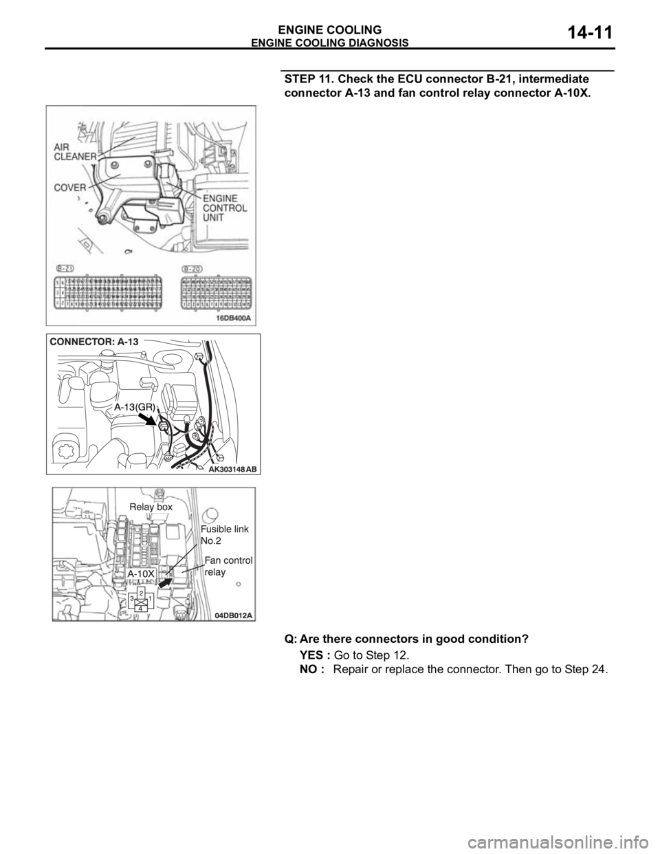
STEP 11. Check the ECU connector B-21, intermediate
connector A-13 and fan control relay connector A-10X.
Q: Are there connectors in good condition?
YES : Go to Step 12.
NO : Repair or replace the connector. Then go to Step 24.
Page 932 of 1500
ENGINE COOLING DIAGNOSIS
ENGINE COOLING14-17
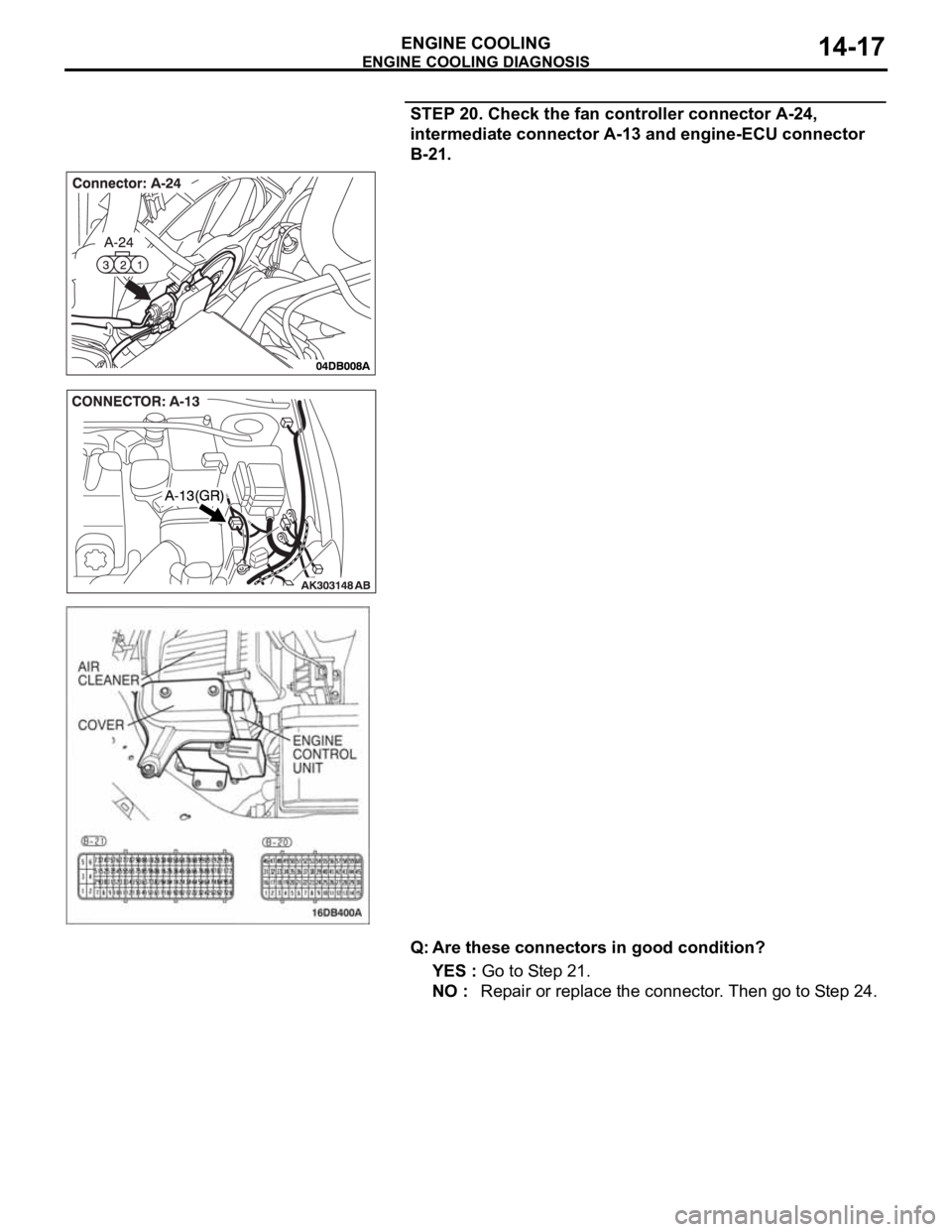
STEP 20. Check the fan controller connector A-24,
intermediate connector A-13 and engine-ECU connector
B-21.
Q: Are these connectors in good condition?
YES : Go to Step 21.
NO : Repair or replace the connector. Then go to Step 24.
Page 933 of 1500
ENGINE COOLING DIAGNOSIS
ENGINE COOLING14-18
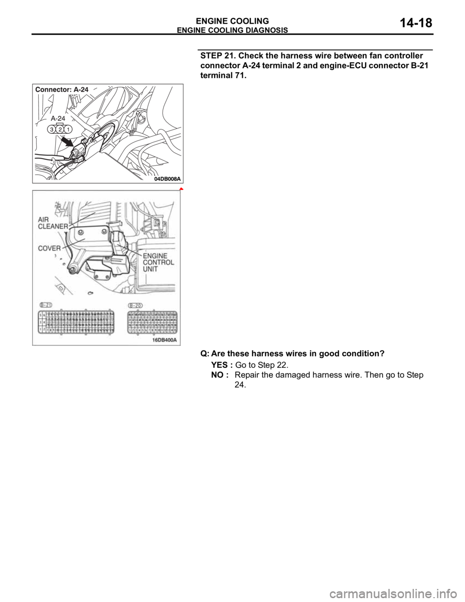
STEP 21. Check the harness wire between fan controller
connector A-24 terminal 2 and engine-ECU connector B-21
terminal 71.
Q: Are these harness wires in good condition?
YES : Go to Step 22.
NO : Repair the damaged harness wire. Then go to Step
24.
Page 935 of 1500
ENGINE COOLING DIAGNOSIS
ENGINE COOLING14-20
STEP 23. MUT-III self-diag code
Check if an MPI system self-diag code is set. (Refer to GROUP
13A - Trouble shooting 13A-5).
Q: Diagnosis code set?
YES : Inspection chart for diagnosis code (Refer to GROUP
13A - Trouble shooting 13A-17)
NO : Replace the engine-ECU (Refer to GROUP 13A,
Engine-ECU 13A-675 ). Then go to Step 24.
STEP 24. Check the symptoms.
Q: Does the radiator fan motor and the condenser fan
motor operate correctly?
YES : This symptom is complete.
NO : Return to Step 1.
INSPECTION PROCEDURE 4: Radiator Fan and Condenser Fan do not Change Speed or Stop
.
Radiator Fan and Condenser Fan Drive
Circuit
Refer to 5.
.
TECHNICAL DESCRIPTION
The cause could be a malfunction of the fan con-
troller power supply or earth circuit.
If the communication line wiring harness between
the fan controller and the engine-ECU is
short-circuited to earth, the radiator fan motor
and the condenser fan motor will not rotate.
The cause could also be a malfunction of input
signal from the A/C switch, the water temperature
sensor unit and the vehicle speed sensor
or the output shaft speed sensor to the
engine-ECU.
The cause could also be a malfunction of the fan
controller or the engine-ECU.
.
TROUBLESHOOTING HINTS
Malfunction of fusible link No.2
Malfunction of fan control relay
Malfunction of cooling fan motor
Malfunction of fan controller
Malfunction of engine-ECU
Damaged wiring harness or connector
DIAGNOSIS
STEP 1. Check the fan control relay.
Refer to 14-31.
Q: Is the fan control relay in good condition?
YES : Go to Step 2.
NO : Replace the fan control relay. Then go to Step 8.
Page 937 of 1500
ENGINE COOLING DIAGNOSIS
ENGINE COOLING14-22
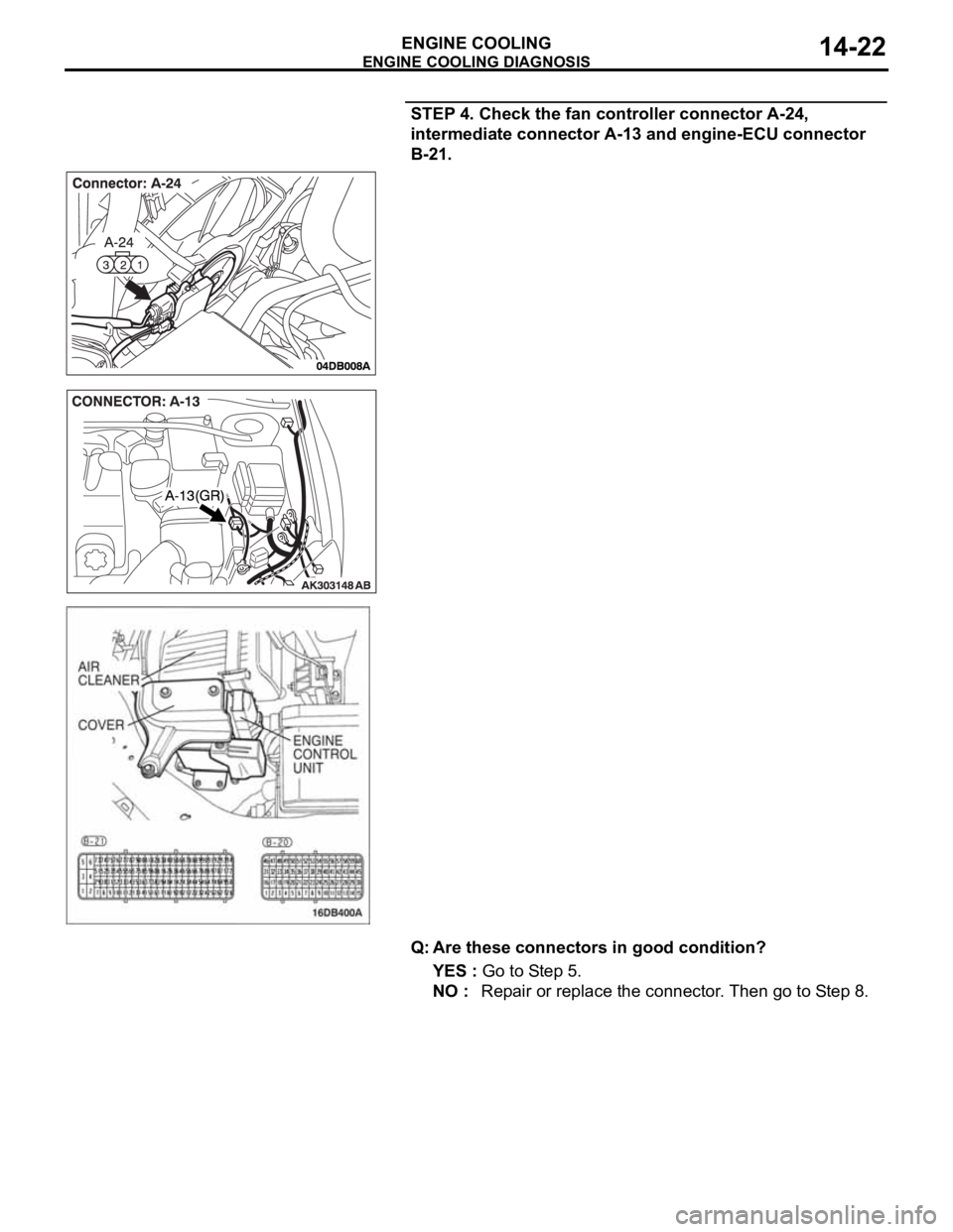
STEP 4. Check the fan controller connector A-24,
intermediate connector A-13 and engine-ECU connector
B-21.
Q: Are these connectors in good condition?
YES : Go to Step 5.
NO : Repair or replace the connector. Then go to Step 8.
Page 938 of 1500
ENGINE COOLING DIAGNOSIS
ENGINE COOLING14-23
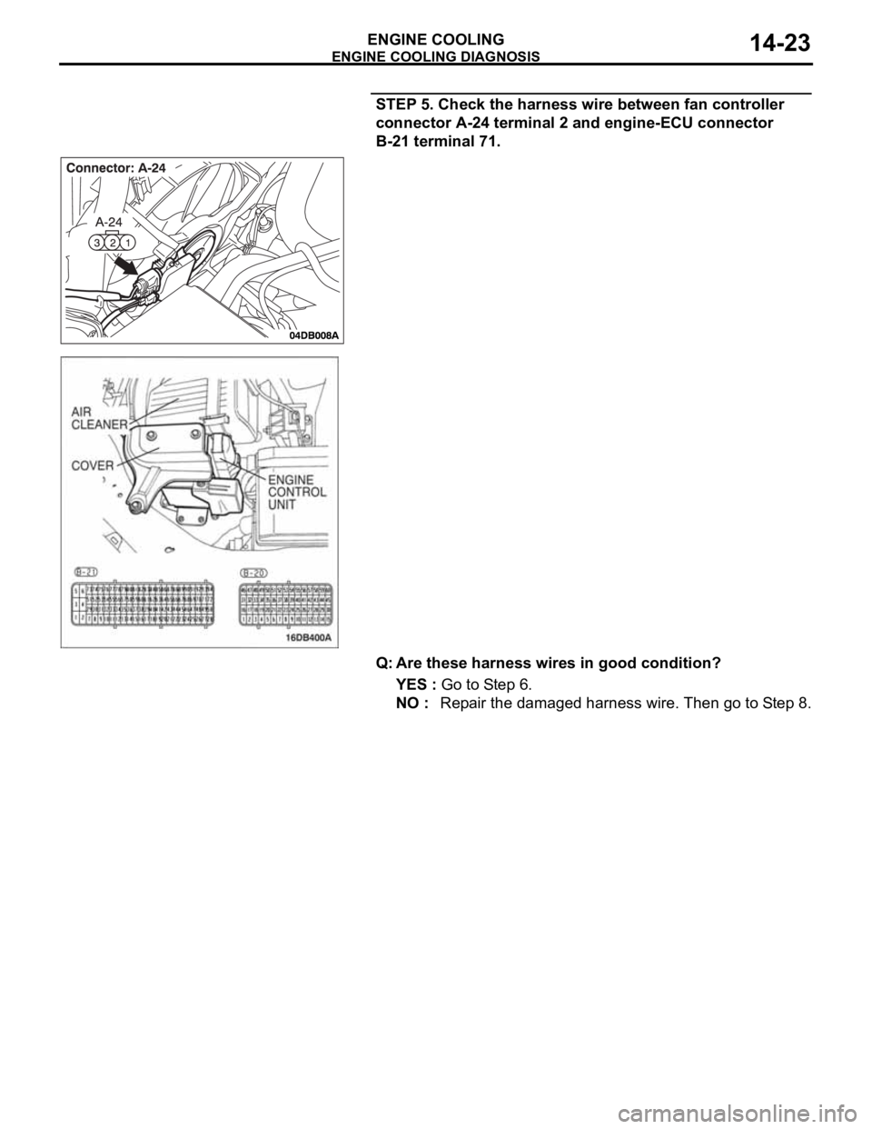
STEP 5. Check the harness wire between fan controller
connector A-24 terminal 2 and engine-ECU connector
B-21 terminal 71.
Q: Are these harness wires in good condition?
YES : Go to Step 6.
NO : Repair the damaged harness wire. Then go to Step 8.
Page 940 of 1500
ENGINE COOLING DIAGNOSIS
ENGINE COOLING14-25
STEP 7. MUT-III self-diag code
Check if an MPI system self-diag code is set. (Refer to GROUP
13A - Trouble shooting 13A-5)
Q: Diagnosis code set?
YES : Inspection chart for diagnosis code (Refer to GROUP
13A - Trouble shooting 13A-5)
NO : Replace the engine-ECU (Refer to GROUP 13A,
Engine-ECU 13A-675 ) Then go to Step 8 .
STEP 8. Check the symptoms.
Q: Does the radiator fan motor and the condenser fan
motor operate correctly?
YES : This symptom is complete.
NO : Return to Step 1.
INSPECTION PROCEDURE 5: Radiator Fan does not Operate
.
Radiator Fan and Condenser Fan Drive
Circuit
.
TECHNICAL DESCRIPTION
The cause could be a malfunction of the radiator fan
motor or an open circuit between the fan controller
and the radiator fan motor.
.
TROUBLESHOOTING HINTS
Malfunction of radiator fan motor
Malfunction of fan controller
Refer to component locations GROUP-1
Refer to configuration diagrams GROUP-1
Refer to circuit diagrams GROUP-1
DIAGNOSIS
Replace the radiator fan motor and fan controller assembly.
Q: Does the radiator fan operate correctly?
YES : There is no action to be taken?
NO : Repair the wiring harness between the fan controller
and the radiator fan motor.
INSPECTION PROCEDURE 6: Condenser Fan does not Operate
.
Radiator Fan and Condenser Fan Drive
Circuit
.
TECHNICAL DESCRIPTION
The cause could be a malfunction of the condenser
fan motor or fan controller.
.
TROUBLESHOOTING HINTS
Malfunction of condenser fan motor
Malfunction of fan controller
Refer to component locations GROUP-1
Refer to configuration diagrams GROUP-1
Refer to circuit diagrams GROUP-1
Page 943 of 1500
ON-VEHICLE SERVICE
ENGINE COOLING14-28
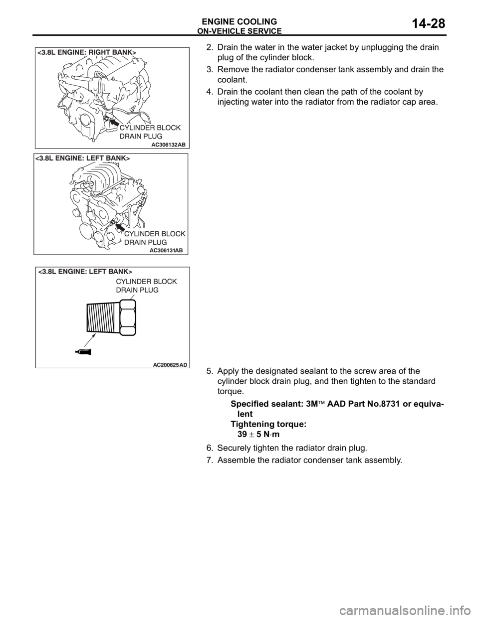
2. Drain the water in the water jacket by unplugging the drain
plug of the cylinder block.
3. Remove the radiator condenser tank assembly and drain the
coolant.
4. Drain the coolant then clean the path of the coolant by
injecting water into the radiator from the radiator cap area.
5. Apply the designated sealant to the screw area of the
cylinder block drain plug, and then tighten to the standard
torque.
Specified sealant: 3M
AAD Part No.8731 or equiva-
lent
Tightening torque:
39
5 Nm
6. Securely tighten the radiator drain plug.
7. Assemble the radiator condenser tank assembly.