ECU MITSUBISHI 380 2005 Workshop Manual
[x] Cancel search | Manufacturer: MITSUBISHI, Model Year: 2005, Model line: 380, Model: MITSUBISHI 380 2005Pages: 1500, PDF Size: 47.87 MB
Page 830 of 1500
AUTO A/C DIAGNOSIS
HEATER, AIR CONDITIONING AND VENTILATION55-129
DIAGNOSIS
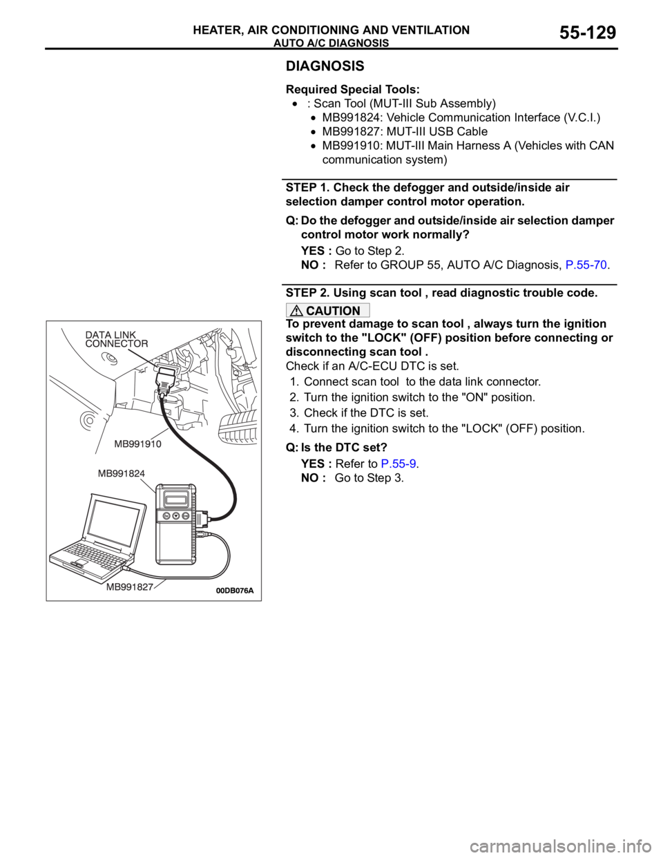
Required Special Tools:
: Scan Tool (MUT-III Sub Assembly)
MB991824: Vehicle Communication Interface (V.C.I.)
MB991827: MUT-III USB Cable
MB991910: MUT-III Main Harness A (Vehicles with CAN
communication system)
STEP 1. Check the defogger and outside/inside air
selection damper control motor operation.
Q: Do the defogger and outside/inside air selection damper
control motor work normally?
YES : Go to Step 2.
NO : Refer to GROUP 55, AUTO A/C Diagnosis, P.55-70.
STEP 2. Using scan tool , read diagnostic trouble code.
To prevent damage to scan tool , always turn the ignition
switch to the "LOCK" (OFF) position before connecting or
disconnecting scan tool .
Check if an A/C-ECU DTC is set.
1. Connect scan tool to the data link connector.
2. Turn the ignition switch to the "ON" position.
3. Check if the DTC is set.
4. Turn the ignition switch to the "LOCK" (OFF) position.
Q: Is the DTC set?
YES : Refer to P.55-9.
NO : Go to Step 3.
Page 832 of 1500
AUTO A/C DIAGNOSIS
HEATER, AIR CONDITIONING AND VENTILATION55-131
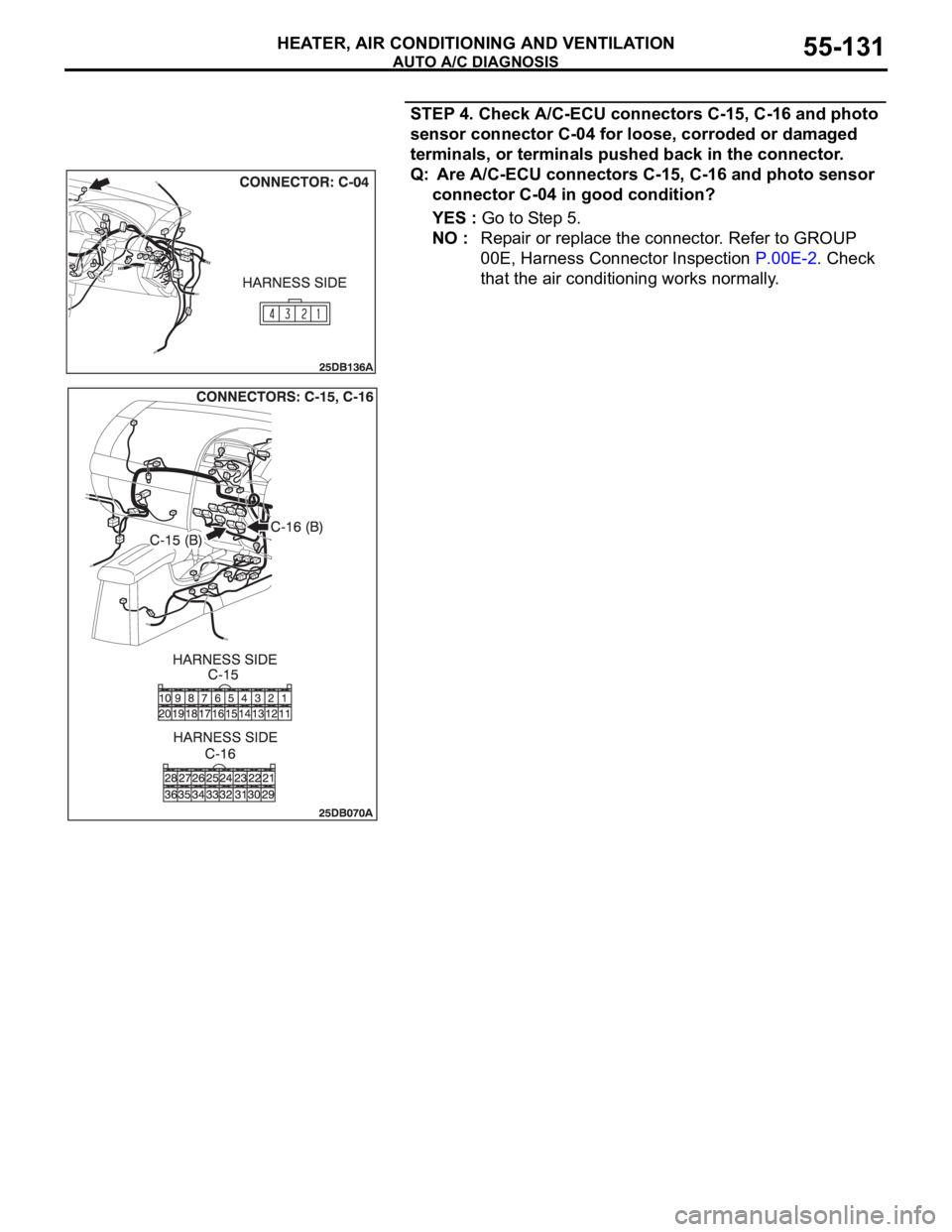
STEP 4. Check A/C-ECU connectors C-15, C-16 and photo
sensor connector C-04 for loose, corroded or damaged
terminals, or terminals pushed back in the connector.
Q: Are A/C-ECU connectors C-15, C-16 and photo sensor
connector C-04 in good condition?
YES : Go to Step 5.
NO : Repair or replace the connector. Refer to GROUP
00E, Harness Connector Inspection P.00E-2. Check
that the air conditioning works normally.
Page 833 of 1500
AUTO A/C DIAGNOSIS
HEATER, AIR CONDITIONING AND VENTILATION55-132
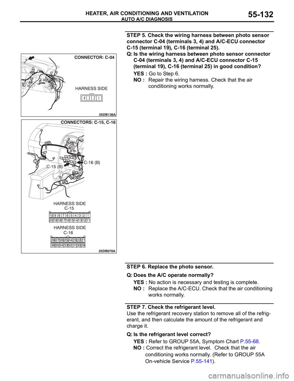
STEP 5. Check the wiring harness between photo sensor
connector C-04 (terminals 3, 4) and A/C-ECU connector
C-15 (terminal 19), C-16 (terminal 25).
Q: Is the wiring harness between photo sensor connector
C-04 (terminals 3, 4) and A/C-ECU connector C-15
(terminal 19), C-16 (terminal 25) in good condition?
YES : Go to Step 6.
NO : Repair the wiring harness. Check that the air
conditioning works normally.
STEP 6. Replace the photo sensor.
Q: Does the A/C operate normally?
YES : No action is necessary and testing is complete.
NO : Replace the A/C-ECU. Check that the air conditioning
works normally.
STEP 7. Check the refrigerant level.
Use the refrigerant recovery station to remove all of the refrig-
erant, and then calculate the amount of the refrigerant and
charge it.
Q: Is the refrigerant level correct?
YES : Refer to GROUP 55A, Symptom Chart P.55-68.
NO : Correct the refrigerant level. Check that the air
conditioning works normally. (Refer to GROUP 55A
On-vehicle Service P.55-141).
Page 838 of 1500

AUTO A/C DIAGNOSIS
HEATER, AIR CONDITIONING AND VENTILATION55-137
CHECK AT A/C-ECU TERMINALM1552010300572
TERMINAL
NO.CHECK ITEM CHECKING REQUIREMENTS NORMAL CONDITION
1 Air mixing damper control motor When the air mix damper is
moved to the MAX. COOL
position. 10 V
When the air mix damper is
moved to the MAX. HOT
position. 0.5 V
2 Air mixing damper control motor When the air mix damper is
moved to the MAX. COOL
position. 0.5 V
When the air mix damper is
moved to the MAX. HOT
position. 10 V
3 Back-up power supply Always Battery positive voltage
4 Mode selection damper control
motor (DEF)When the damper is moved to
the FACE position. 0.5 V
When the damper is moved to
the DEF position. 10 V
5 Outside/inside air selection
damper control motor (outside)When the damper is moved to
the inside air recirculation
position.0.5 V
When the damper is moved to
the outside air induction
position.0 V (when the motor is
stopped)
6 Outside/inside air selection
damper control motor (inside)When the damper is moved to
the inside air recirculation
position.0 V (when the motor is
stopped)
When the damper is moved to
the outside air induction
position.0.5 V
8 Rear defogger relay Ignition switch: ON Battery positive voltage
9 Front blower relay Ignition switch: ON Battery positive voltage
10 A/C compressor relay A/C compressor relay: ON Battery positive voltage
11 Mode selection damper control
motor (FACE)When the damper is moved to
the FACE position. 10 V
When the damper is moved to
the DEF position. 0.5 V
12 A/C pressure sensor Ignition switch: ON 5 V
Page 850 of 1500
ON-VEHICLE SERVICE
HEATER, AIR CONDITIONING AND VENTILATION55-149
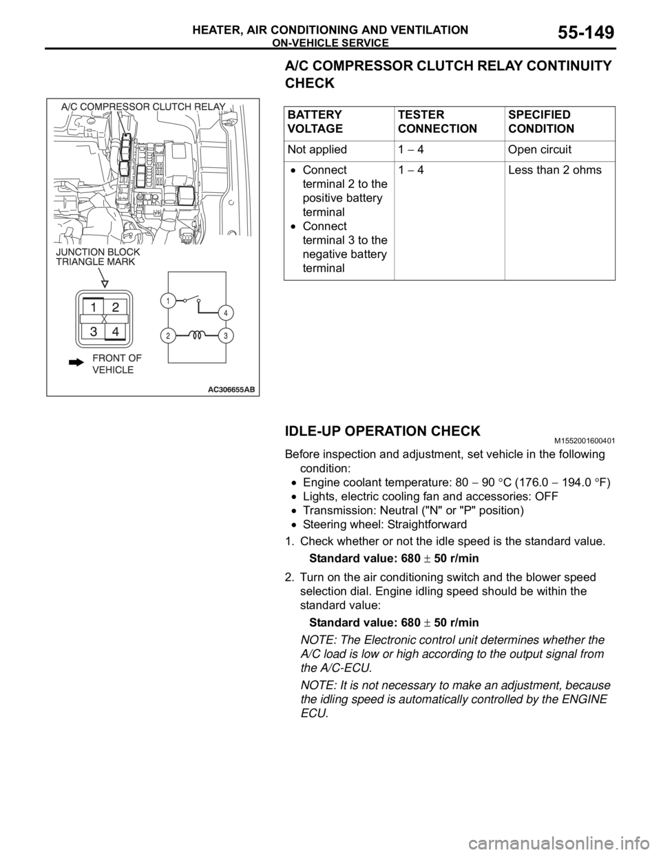
A/C COMPRESSOR CLUTCH RELAY CONTINUITY
CHECK
IDLE-UP OPERATION CHECK
M1552001600401
Before inspection and adjustment, set vehicle in the following
condition:
Engine coolant temperature: 80 90 C (176.0 194.0 F)
Lights, electric cooling fan and accessories: OFF
Transmission: Neutral ("N" or "P" position)
Steering wheel: Straightforward
1. Check whether or not the idle speed is the standard value.
Standard value: 680
50 r/min
2. Turn on the air conditioning switch and the blower speed
selection dial. Engine idling speed should be within the
standard value:
Standard value: 680
50 r/min
NOTE: The Electronic control unit determines whether the
A/C load is low or high according to the output signal from
the A/C-ECU.
NOTE: It is not necessary to make an adjustment, because
the idling speed is automatically controlled by the ENGINE
ECU. BATTERY
V O LTA G ETESTER
CONNECTIONSPECIFIED
CONDITION
Not applied 1
4 Open circuit
Connect
terminal 2 to the
positive battery
terminal
Connect
terminal 3 to the
negative battery
terminal1
4 Less than 2 ohms
Page 851 of 1500
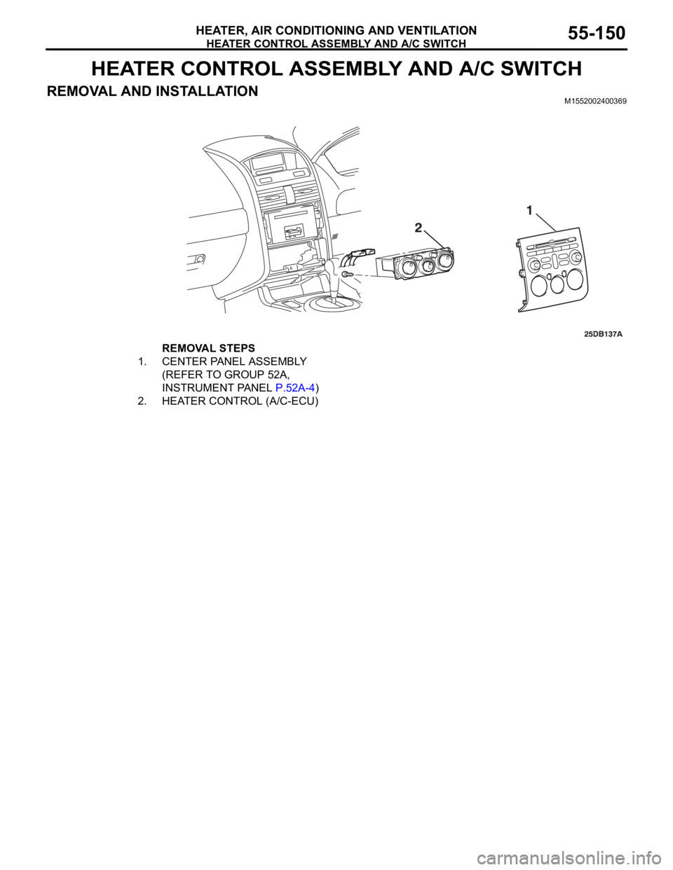
HEATER CONTROL ASSEMBLY AND A/C SWITCH
HEATER, AIR CONDITIONING AND VENTILATION55-150
HEATER CONTROL ASSEMBLY AND A/C SWITCH
REMOVAL AND INSTALLATIONM1552002400369
REMOVAL STEPS
1. CENTER PANEL ASSEMBLY
(REFER TO GROUP 52A,
INSTRUMENT PANEL P.52A-4)
2. HEATER CONTROL (A/C-ECU)
Page 853 of 1500
HEATER UNIT, HEATER CORE, BLOWER ASSEMBLY AND EVAPORATOR UNIT
HEATER, AIR CONDITIONING AND VENTILATION55-152
REMOVAL SERVICE POINTS
.
<> SUCTION PIPE AND LIQUID PIPE DISCON-
NECTION
As the compressor oil and receiver are highly moisture
absorbent, use a non-porous material to plug the hose and
nipples.
To prevent the entry of dust or other foreign bodies, plug the
dismantled hose and the nipples of the expansion valves.
.
<> HEATER UNIT AND DECK
CROSSMEMBER ASSEMBLY REMOVAL
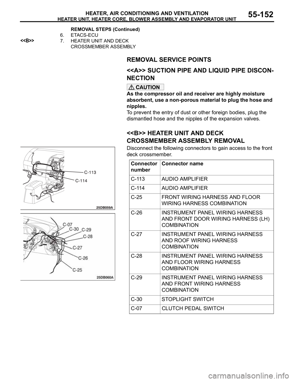
Disconnect the following connectors to gain access to the front
deck crossmember.
6. ETACS-ECU
<>7. HEATER UNIT AND DECK
CROSSMEMBER ASSEMBLY REMOVAL STEPS (Continued)
Connector
numberConnector name
C-113 AUDIO AMPLIFIER
C-114 AUDIO AMPLIFIER
C-25 FRONT WIRING HARNESS AND FLOOR
WIRING HARNESS COMBINATION
C-26 INSTRUMENT PANEL WIRING HARNESS
AND FRONT DOOR WIRING HARNESS (LH)
COMBINATION
C-27 INSTRUMENT PANEL WIRING HARNESS
AND ROOF WIRING HARNESS
COMBINATION
C-28 INSTRUMENT PANEL WIRING HARNESS
AND FLOOR WIRING HARNESS
COMBINATION
C-29 INSTRUMENT PANEL WIRING HARNESS
AND FRONT WIRING HARNESS
COMBINATION
C-30 STOPLIGHT SWITCH
C-07 CLUTCH PEDAL SWITCH
Page 893 of 1500
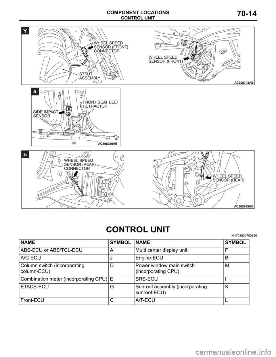
CONTROL UNIT
COMPONENT LOCATIONS70-14
CONTROL UNITM1701000700360
NAME SYMBOL NAME SYMBOL
ABS-ECU or ABS/TCL-ECU A Multi center display unit F
A/C-ECU J Engine-ECU B
Column switch (incorporating
column-ECU)D Power window main switch
(incorporating CPU)M
Combination meter (incorporating CPU) E SRS-ECU I
ETACS-ECU G Sunroof assembly (incorporating
sunroof-ECU)K
Front-ECU C A/T-ECU L
Page 904 of 1500
HOW TO DIAGNOSE
GENERAL
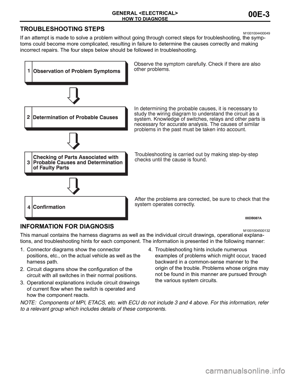
TROUBLESHOOTING STEPSM1001004400049
If an attempt is made to solve a problem without going through correct steps for troubleshooting, the symp-
toms could become more complicated, resulting in failure to determine the causes correctly and making
incorrect repairs. The four steps below should be followed in troubleshooting.
INFORMATION FOR DIAGNOSISM1001004500132
This manual contains the harness diagrams as well as the individual circuit drawings, operational explana-
tions, and troubleshooting hints for each component. The information is presented in the following manner:
1. Connector diagrams show the connector
positions, etc., on the actual vehicle as well as the
harness path.
2. Circuit diagrams show the configuration of the
circuit with all switches in their normal positions.
3. Operational explanations include circuit drawings
of current flow when the switch is operated and
how the component reacts.4. Troubleshooting hints include numerous
examples of problems which might occur, traced
backward in a common-sense manner to the
origin of the trouble. Problems whose origins may
not be found in this manner are pursued through
the various system circuits.
NOTE: Components of MPI, ETACS, etc. with ECU do not include 3 and 4 above. For this information, refer
to a relevant group which includes details of these components.
Page 906 of 1500
HOW TO DIAGNOSE
GENERAL
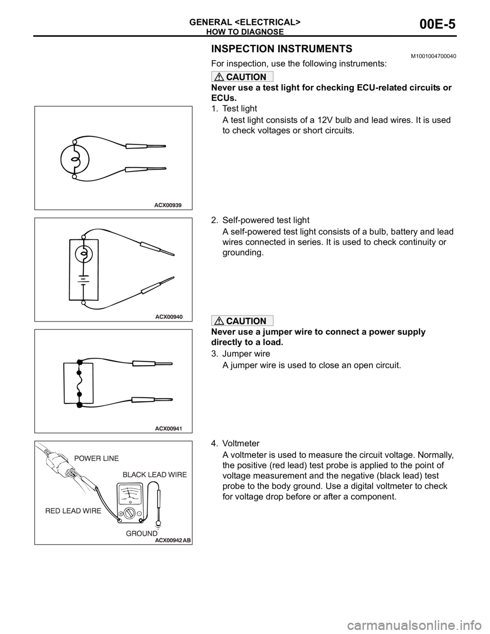
INSPECTION INSTRUMENTSM1001004700040
For inspection, use the following instruments:
Never use a test light for checking ECU-related circuits or
ECUs.
1. Test light
A test light consists of a 12V bulb and lead wires. It is used
to check voltages or short circuits.
2. Self-powered test light
A self-powered test light consists of a bulb, battery and lead
wires connected in series. It is used to check continuity or
grounding.
Never use a jumper wire to connect a power supply
directly to a load.
3. Jumper wire
A jumper wire is used to close an open circuit.
4. Voltmeter
A voltmeter is used to measure the circuit voltage. Normally,
the positive (red lead) test probe is applied to the point of
voltage measurement and the negative (black lead) test
probe to the body ground. Use a digital voltmeter to check
for voltage drop before or after a component.