ECU MITSUBISHI 380 2005 Workshop Manual
[x] Cancel search | Manufacturer: MITSUBISHI, Model Year: 2005, Model line: 380, Model: MITSUBISHI 380 2005Pages: 1500, PDF Size: 47.87 MB
Page 1395 of 1500
AUTO-CRUISE CONTROL
ENGINE AND EMISSION CONTROL17-64
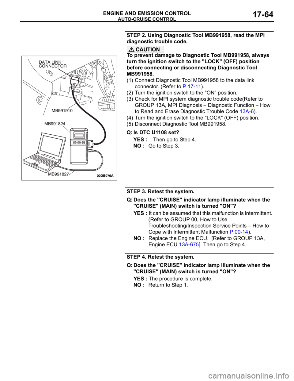
STEP 2. Using Diagnostic Tool MB991958, read the MPI
diagnostic trouble code.
To prevent damage to Diagnostic Tool MB991958, always
turn the ignition switch to the "LOCK" (OFF) position
before connecting or disconnecting Diagnostic Tool
MB991958.
(1) Connect Diagnostic Tool MB991958 to the data link
connector. (Refer to P.17-11).
(2) Turn the ignition switch to the "ON" position.
(3) Check for MPI system diagnostic trouble code(Refer to
GROUP 13A, MPI Diagnosis
Diagnostic Function How
to Read and Erase Diagnostic Trouble Code 13A-6).
(4) Turn the ignition switch to the "LOCK" (OFF) position.
(5) Disconnect Diagnostic Tool MB991958.
Q: Is DTC U1108 set?
YES : . Then go to Step 4.
NO : Go to Step 3.
STEP 3. Retest the system.
Q: Does the "CRUISE" indicator lamp illuminate when the
"CRUISE" (MAIN) switch is turned "ON"?
YES : It can be assumed that this malfunction is intermittent.
(Refer to GROUP 00, How to Use
Troubleshooting/Inspection Service Points
How to
Cope with Intermittent Malfunction P.00-14).
NO : Replace the Engine ECU. [Refer to GROUP 13A,
Engine ECU 13A-675]. Then go to Step 4.
STEP 4. Retest the system.
Q: Does the "CRUISE" indicator lamp illuminate when the
"CRUISE" (MAIN) switch is turned "ON"?
YES : The procedure is complete.
NO : Return to Step 1.
Page 1398 of 1500
AUTO-CRUISE CONTROL
ENGINE AND EMISSION CONTROL17-67
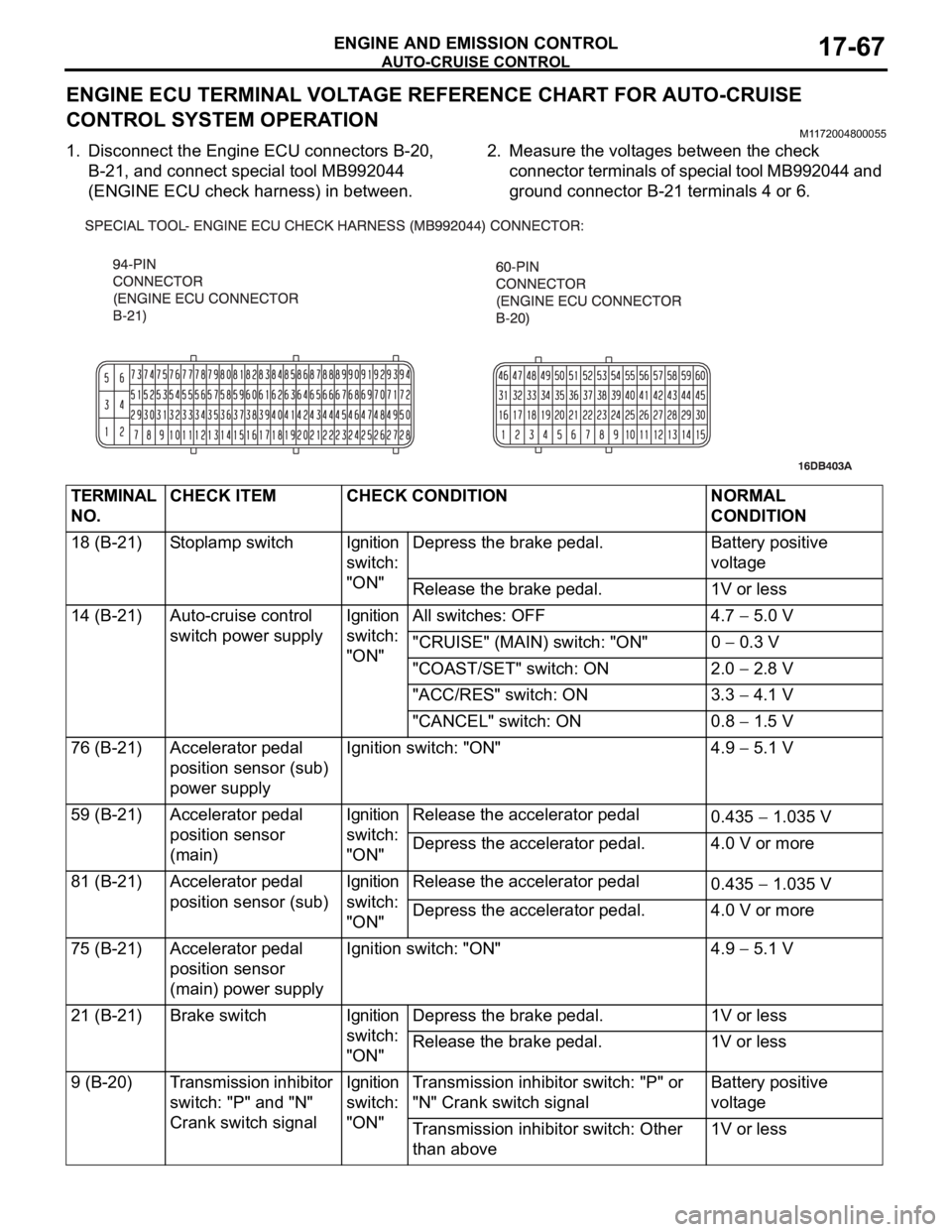
ENGINE ECU TERMINAL VOLTAGE REFERENCE CHART FOR AUTO-CRUISE
CONTROL SYSTEM OPERATION
M1172004800055
1. Disconnect the Engine ECU connectors B-20,
B-21, and connect special tool MB992044
(ENGINE ECU check harness) in between.2. Measure the voltages between the check
connector terminals of special tool MB992044 and
ground connector B-21 terminals 4 or 6.
TERMINAL
NO.CHECK ITEM CHECK CONDITION NORMAL
CONDITION
18 (B-21) Stoplamp switch Ignition
switch:
"ON"Depress the brake pedal. Battery positive
voltage
Release the brake pedal. 1V or less
14 (B-21) Auto-cruise control
switch power supplyIgnition
switch:
"ON"All switches: OFF 4.7
5.0 V
"CRUISE" (MAIN) switch: "ON" 0
0.3 V
"COAST/SET" switch: ON 2.0
2.8 V
"ACC/RES" switch: ON 3.3
4.1 V
"CANCEL" switch: ON 0.8
1.5 V
76 (B-21) Accelerator pedal
position sensor (sub)
power supplyIgnition switch: "ON" 4.9
5.1 V
59 (B-21) Accelerator pedal
position sensor
(main)Ignition
switch:
"ON"Release the accelerator pedal
0.435
1.035 V
Depress the accelerator pedal. 4.0 V or more
81 (B-21) Accelerator pedal
position sensor (sub)Ignition
switch:
"ON"Release the accelerator pedal
0.435
1.035 V
Depress the accelerator pedal. 4.0 V or more
75 (B-21) Accelerator pedal
position sensor
(main) power supplyIgnition switch: "ON" 4.9
5.1 V
21 (B-21) Brake switch Ignition
switch:
"ON"Depress the brake pedal. 1V or less
Release the brake pedal. 1V or less
9 (B-20) Transmission inhibitor
switch: "P" and "N"
Crank switch signalIgnition
switch:
"ON"Transmission inhibitor switch: "P" or
"N" Crank switch signalBattery positive
voltage
Transmission inhibitor switch: Other
than above1V or less
Page 1401 of 1500

AUTO-CRUISE CONTROL
ENGINE AND EMISSION CONTROL17-70
MB991223
A: MB991219
B: MB991220
C: MB991221
D: MB991222
Harness set
A: Inspection harness
B: LED harness
C: LED harness adapter
D: ProbeGeneral service tools Checking the continuity
and measuring the
voltage at the harness
connector
MB992044
Engine ECU check
harness
Measuring the terminal
voltage at the Engine
ECU
MB992045
Auto Trans. ECU check
harness
Measuring the terminal
voltage at the Auto Trans.
ECU TOOL TOOL NUMBER AND
NAMESUPERSESSION APPLICATION
Page 1406 of 1500
AUTO-CRUISE CONTROL
ENGINE AND EMISSION CONTROL17-75
AUTO-CRUISE CONTROL
REMOVAL AND INSTALLATIONM1172001400467
Before removal of the air bag module, refer to GROUP 52B, SRS Service Precautions
P.52B-16 and GROUP 52B, Air Bag Module and Clock Spring P.52B-237.
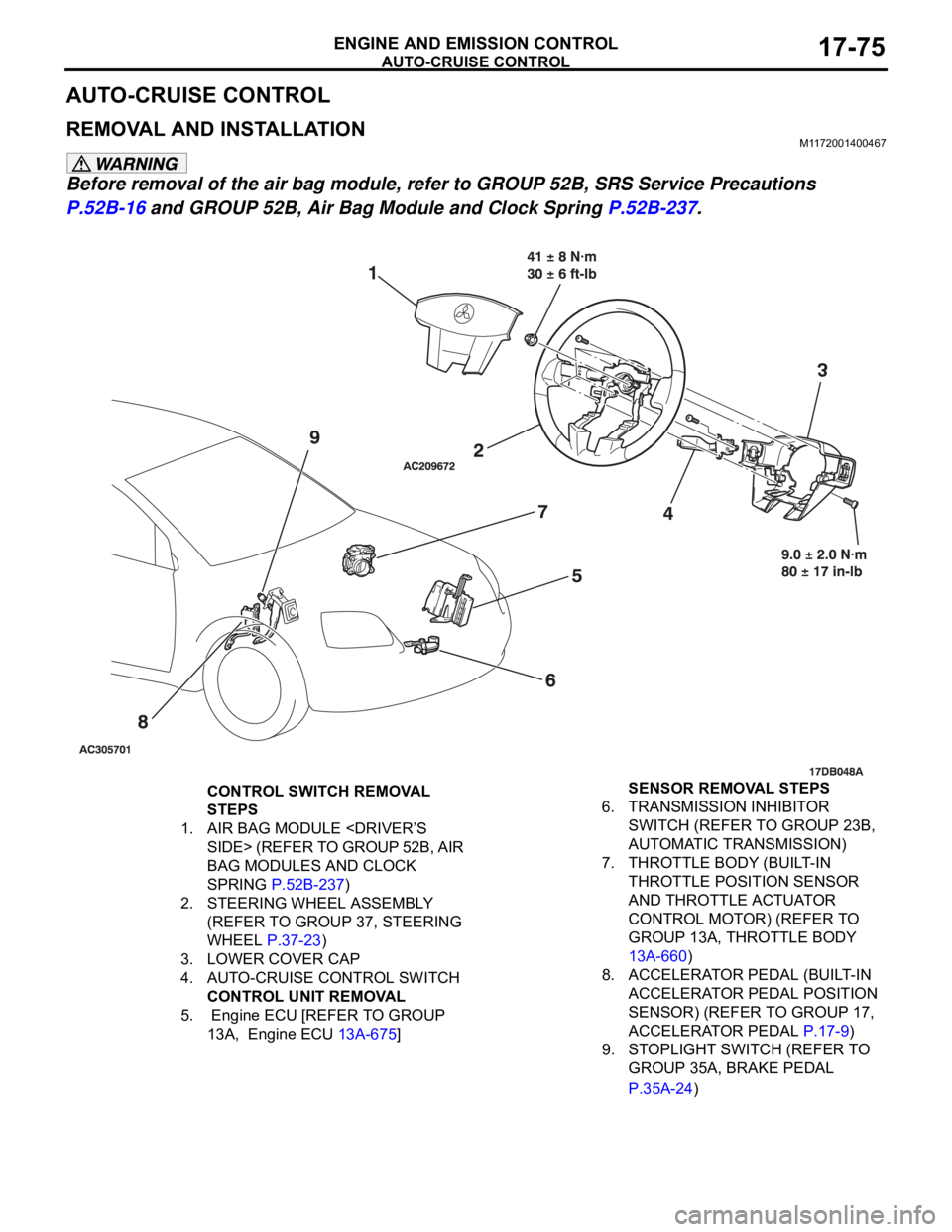
CONTROL SWITCH REMOVAL
STEPS
1. AIR BAG MODULE
BAG MODULES AND CLOCK
SPRING P.52B-237)
2. STEERING WHEEL ASSEMBLY
(REFER TO GROUP 37, STEERING
WHEEL P.37-23)
3. LOWER COVER CAP
4. AUTO-CRUISE CONTROL SWITCH
CONTROL UNIT REMOVAL
5. Engine ECU [REFER TO GROUP
13A, Engine ECU 13A-675] SENSOR REMOVAL STEPS
6. TRANSMISSION INHIBITOR
SWITCH (REFER TO GROUP 23B,
AUTOMATIC TRANSMISSION)
7. THROTTLE BODY (BUILT-IN
THROTTLE POSITION SENSOR
AND THROTTLE ACTUATOR
CONTROL MOTOR) (REFER TO
GROUP 13A, THROTTLE BODY
13A-660)
8. ACCELERATOR PEDAL (BUILT-IN
ACCELERATOR PEDAL POSITION
SENSOR) (REFER TO GROUP 17,
ACCELERATOR PEDAL P.17-9)
9. STOPLIGHT SWITCH (REFER TO
GROUP 35A, BRAKE PEDAL
P.35A-24)
Page 1409 of 1500
EMISSION CONTROL
ENGINE AND EMISSION CONTROL17-78
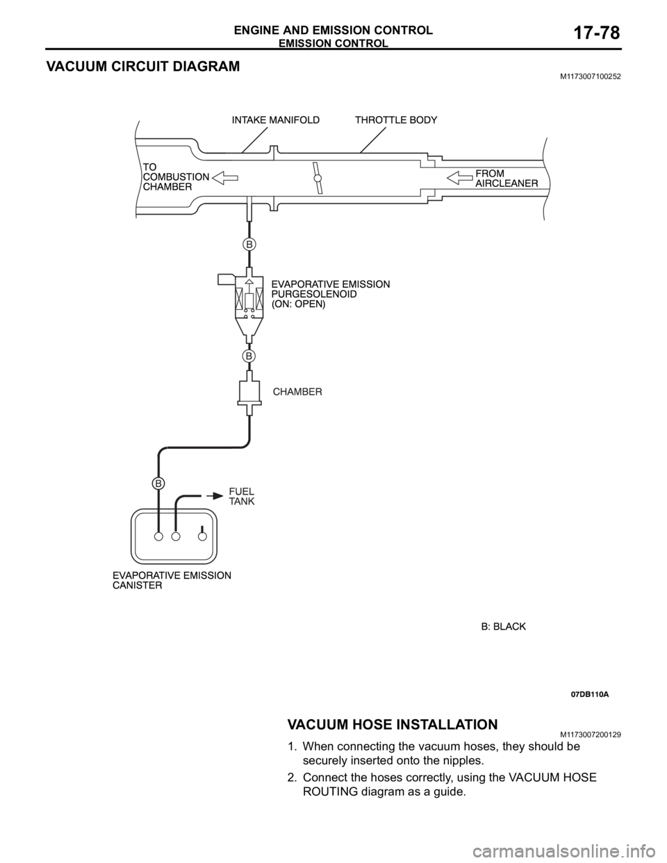
VACUUM CIRCUIT DIAGRAMM1173007100252
VACUUM HOSE INSTALLATIONM1173007200129
1. When connecting the vacuum hoses, they should be
securely inserted onto the nipples.
2. Connect the hoses correctly, using the VACUUM HOSE
ROUTING diagram as a guide.
Page 1412 of 1500
EMISSION CONTROL
ENGINE AND EMISSION CONTROL17-81
EVAPORATIVE EMISSION CONTROL SYSTEM
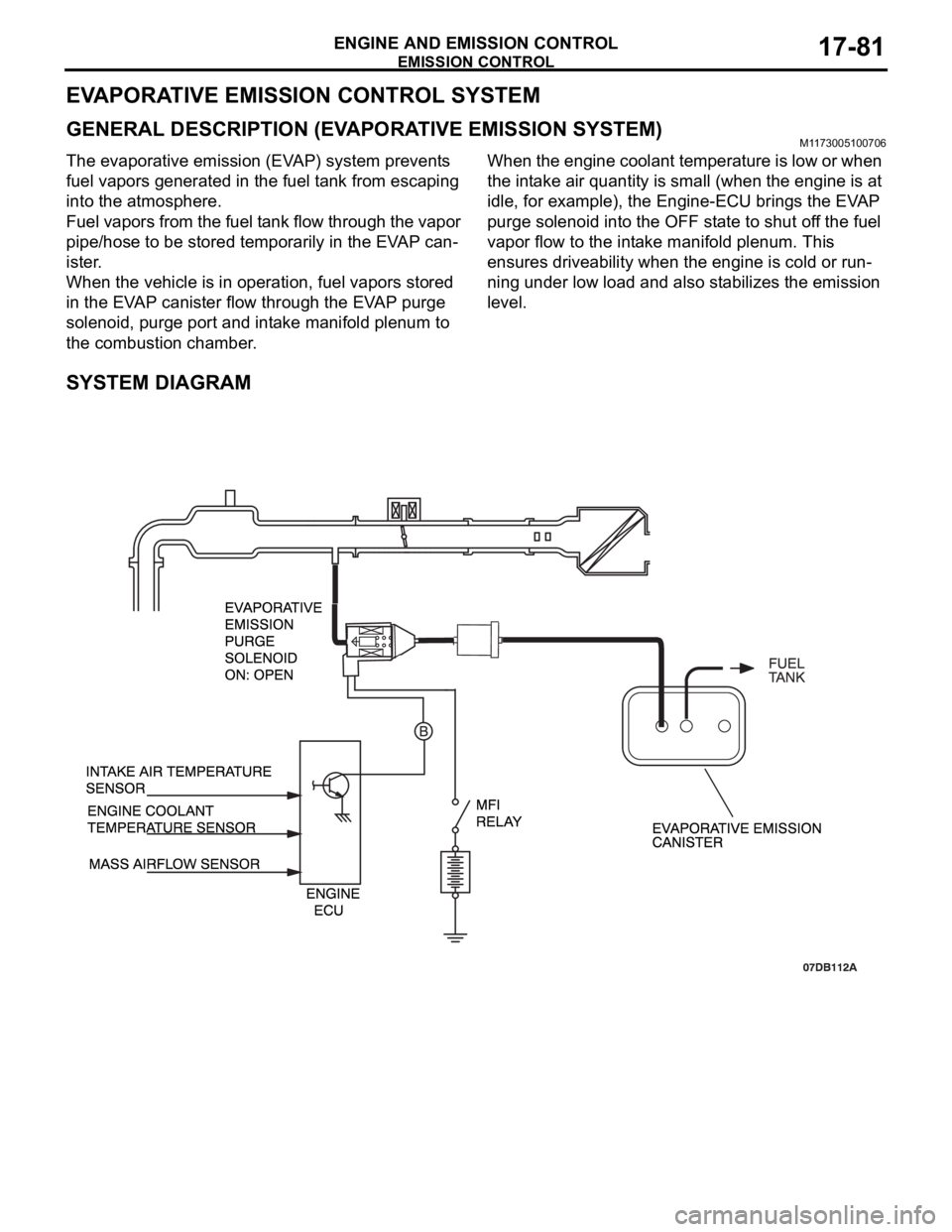
GENERAL DESCRIPTION (EVAPORATIVE EMISSION SYSTEM)M1173005100706
The evaporative emission (EVAP) system prevents
fuel vapors generated in the fuel tank from escaping
into the atmosphere.
Fuel vapors from the fuel tank flow through the vapor
pipe/hose to be stored temporarily in the EVAP can-
ister.
When the vehicle is in operation, fuel vapors stored
in the EVAP canister flow through the EVAP purge
solenoid, purge port and intake manifold plenum to
the combustion chamber.When the engine coolant temperature is low or when
the intake air quantity is small (when the engine is at
idle, for example), the Engine-ECU brings the EVAP
purge solenoid into the OFF state to shut off the fuel
vapor flow to the intake manifold plenum. This
ensures driveability when the engine is cold or run-
ning under low load and also stabilizes the emission
level.
SYSTEM DIAGRAM
Page 1427 of 1500
FRONT AXLE HUB ASSEMBLY
FRONT AXLE26-10
REMOVAL SERVICE POINTS
.
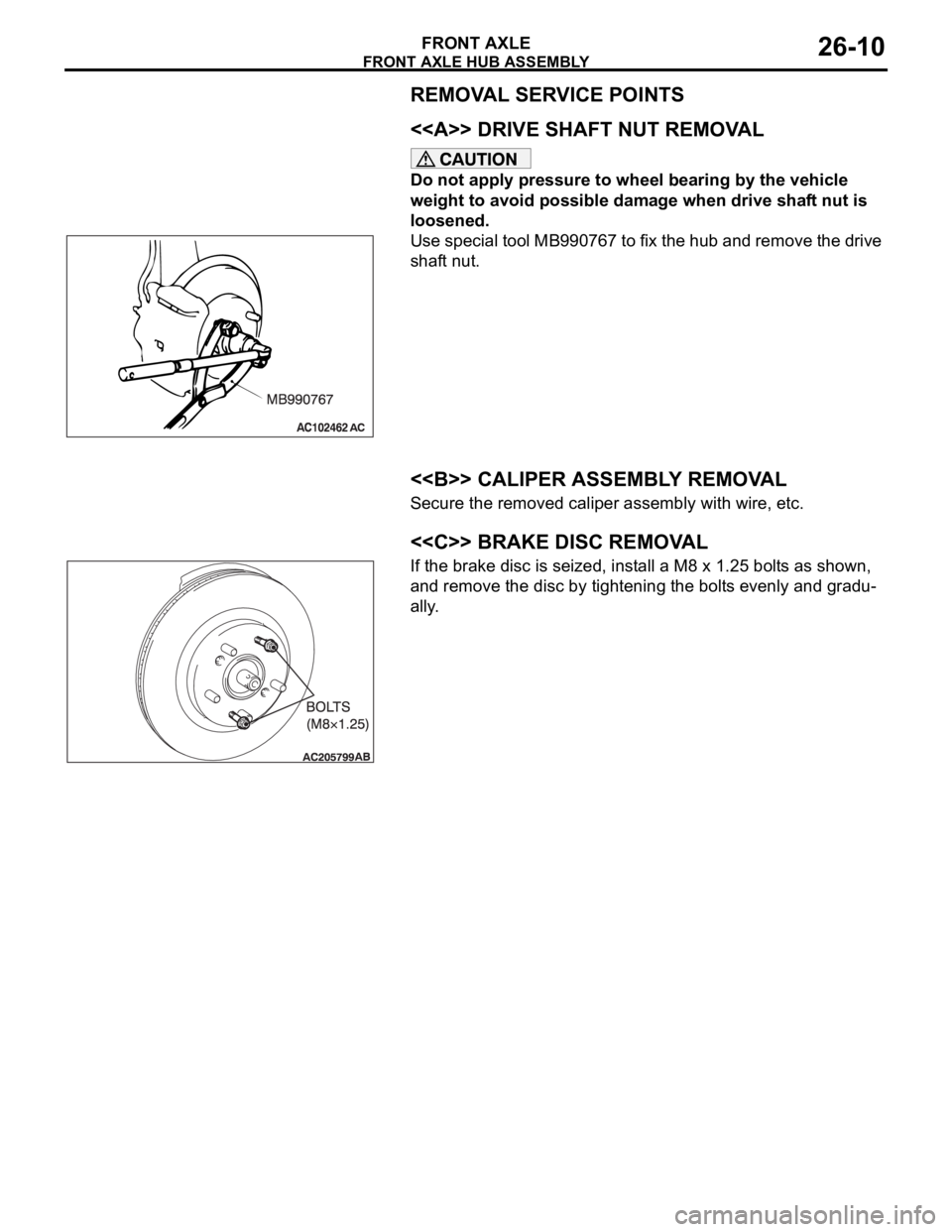
<> DRIVE SHAFT NUT REMOVAL
Do not apply pressure to wheel bearing by the vehicle
weight to avoid possible damage when drive shaft nut is
loosened.
Use special tool MB990767 to fix the hub and remove the drive
shaft nut.
.
<> CALIPER ASSEMBLY REMOVAL
Secure the removed caliper assembly with wire, etc.
.
<
If the brake disc is seized, install a M8 x 1.25 bolts as shown,
and remove the disc by tightening the bolts evenly and gradu-
ally.
.
Page 1429 of 1500
FRONT AXLE HUB ASSEMBLY
FRONT AXLE26-12
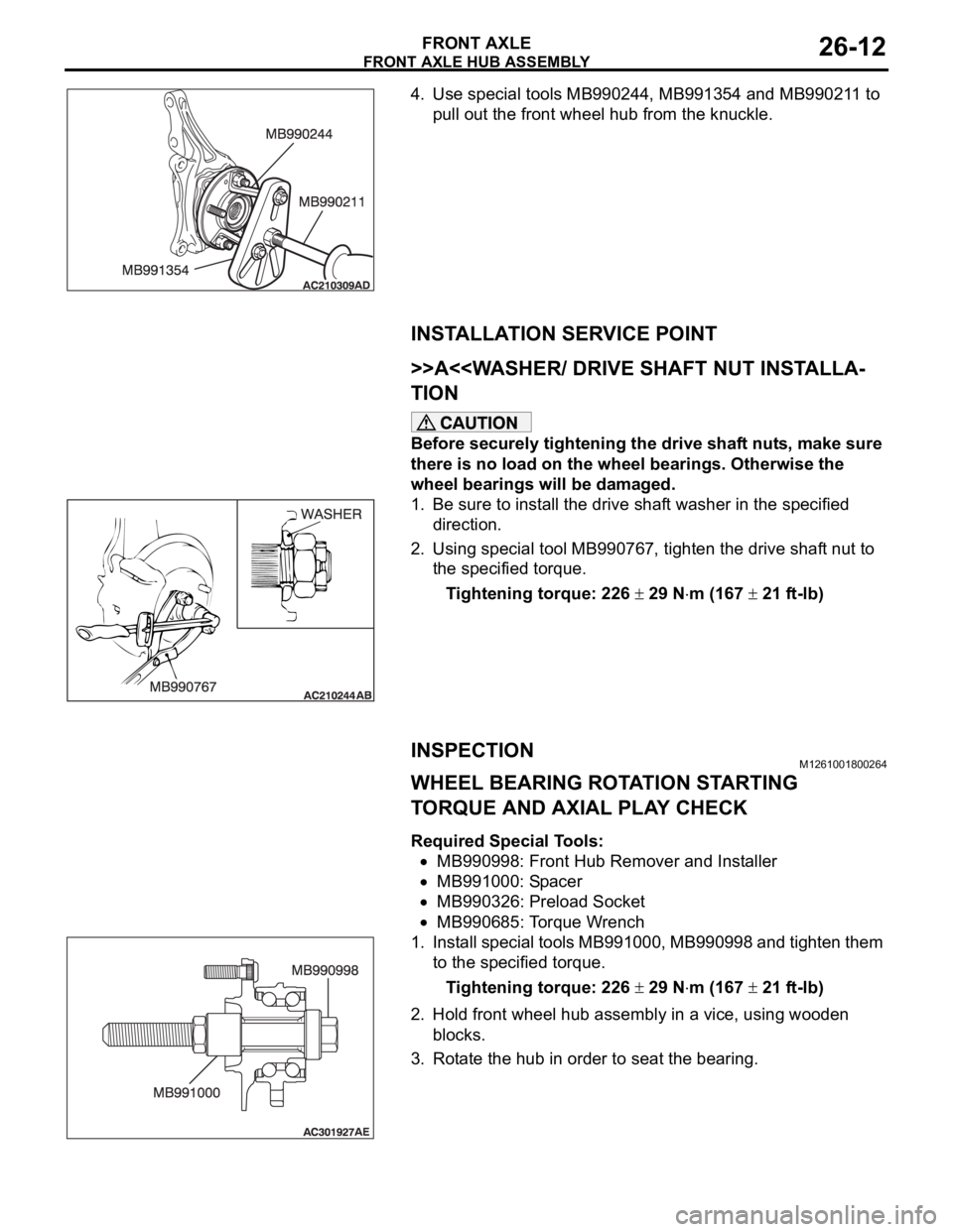
4. Use special tools MB990244, MB991354 and MB990211 to
pull out the front wheel hub from the knuckle.
INSTALLATION SERVICE POINT
.
>>A<
Before securely tightening the drive shaft nuts, make sure
there is no load on the wheel bearings. Otherwise the
wheel bearings will be damaged.
1. Be sure to install the drive shaft washer in the specified
direction.
2. Using special tool MB990767, tighten the drive shaft nut to
the specified torque.
Tightening torque: 226
29 Nm (167 21 ft-lb)
INSPECTIONM1261001800264
WHEEL BEARING ROTATION STARTING
TORQUE AND AXIAL PLAY CHECK
Required Special Tools:
MB990998: Front Hub Remover and Installer
MB991000: Spacer
MB990326: Preload Socket
MB990685: Torque Wrench
1. Install special tools MB991000, MB990998 and tighten them
to the specified torque.
Tightening torque: 226
29 Nm (167 21 ft-lb)
2. Hold front wheel hub assembly in a vice, using wooden
blocks.
3. Rotate the hub in order to seat the bearing.
Page 1434 of 1500
DRIVE SHAFT ASSEMBLY
FRONT AXLE26-17
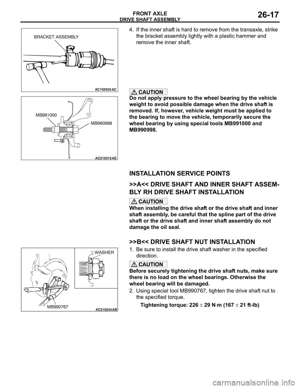
4. If the inner shaft is hard to remove from the transaxle, strike
the bracket assembly lightly with a plastic hammer and
remove the inner shaft.
Do not apply pressure to the wheel bearing by the vehicle
weight to avoid possible damage when the drive shaft is
removed. If, however, vehicle weight must be applied to
the bearing to move the vehicle, temporarily secure the
wheel bearing by using special tools MB991000 and
MB990998.
INSTALLATION SERVICE POINTS
.
>>A<< DRIVE SHAFT AND INNER SHAFT ASSEM-
BLY RH DRIVE SHAFT INSTALLATION
When installing the drive shaft or the drive shaft and inner
shaft assembly, be careful that the spline part of the drive
shaft or the drive shaft and inner shaft assembly do not
damage the oil seal.
.
>>B<< DRIVE SHAFT NUT INSTALLATION
1. Be sure to install the drive shaft washer in the specified
direction.
Before securely tightening the drive shaft nuts, make sure
there is no load on the wheel bearings. Otherwise the
wheel bearing will be damaged.
2. Using special tool MB990767, tighten the drive shaft nut to
the specified torque.
Tightening torque: 226
29 Nm (167 21 ft-lb)
Page 1439 of 1500
DRIVE SHAFT ASSEMBLY
FRONT AXLE26-22
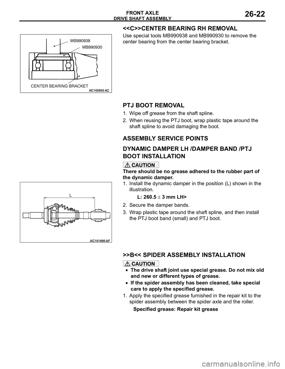
<
Use special tools MB990938 and MB990930 to remove the
center bearing from the center bearing bracket.
.
PTJ BOOT REMOVAL
1. Wipe off grease from the shaft spline.
2. When reusing the PTJ boot, wrap plastic tape around the
shaft spline to avoid damaging the boot.
ASSEMBLY SERVICE POINTS
.
DYNAMIC DAMPER LH /DAMPER BAND /PTJ
BOOT INSTALLATION
There should be no grease adhered to the rubber part of
the dynamic damper.
1. Install the dynamic damper in the position (L) shown in the
illustration.
L: 260.5
3 mm LH>
2. Secure the damper bands.
3. Wrap plastic tape around the shaft spline, and then install
the PTJ boot band (small) and PTJ boot.
.
>>B<< SPIDER ASSEMBLY INSTALLATION
The drive shaft joint use special grease. Do not mix old
and new or different types of grease.
If the spider assembly has been cleaned, take special
care to apply the specified grease.
1. Apply the specified grease furnished in the repair kit to the
spider assembly between the spider axle and the roller.
Specified grease: Repair kit grease